
HOLIDAY DONATION DRIVE - SUPPORT MSW - DO YOUR PART TO KEEP THIS GREAT FORUM GOING! (Only 13 donations so far - C'mon guys!)
×
Marcus.K.
-
Posts
351 -
Joined
-
Last visited
Content Type
Profiles
Forums
Gallery
Events
Everything posted by Marcus.K.
-
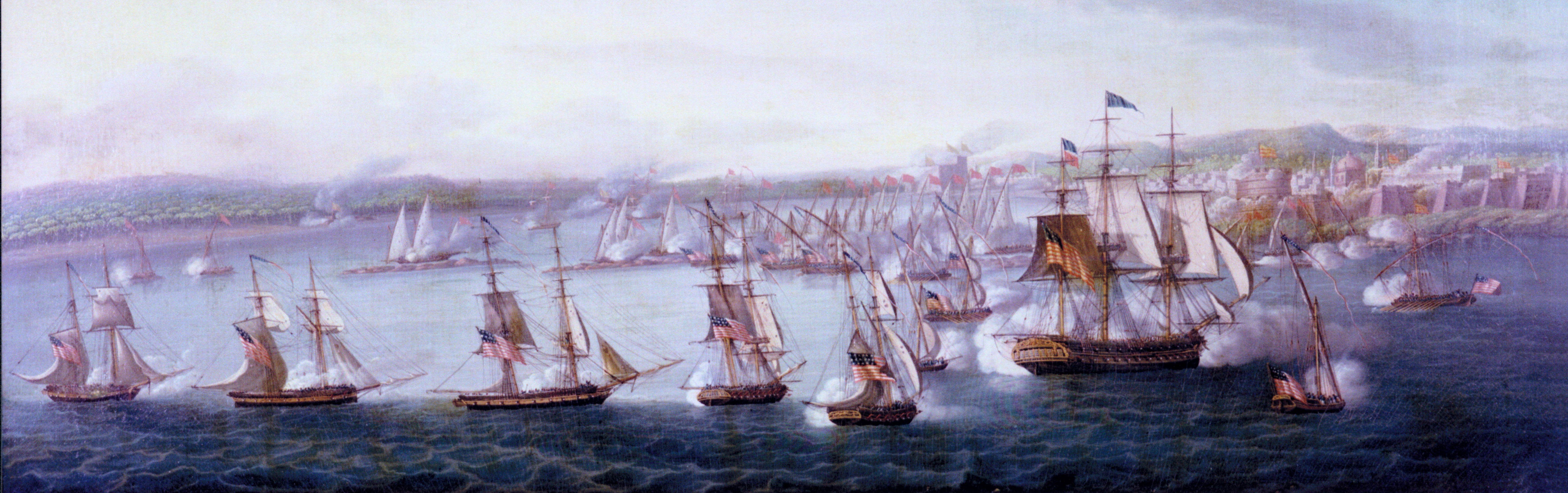
 Ahooy there! What´s up, Doc? thrilling news from Constitutions Log lines - engravings of early US Frigate United States found - go and see: https://ussconstitutionmuseum.org/2016/06/14/federal-frigate-early-views-united-states/ Have fun! But as usually: engravings and paintings have to be "read" with care. They are no photos. Their purpose is not to show the "real" thing 100% accurate. As I pointed out in my comment I doubt that Thomas Clarke was able to see the ship in fully rigging before he had to finalize his edgeing. Also the 16 guns per side - not really realistic? On the other hand: would an Artist be THAT inaccurate? With the most important issue of a war-ship - its armament? Where is the dolphin striker? I am curious about your thinking ...
- 165 replies
-
- 4
-

-
- united states
- revell
- (and 1 more)
-
Hey ho, this Looks really nice! .. I would like to know: how do you work with this "copper" you had? Did you have to scrap off what was on the wooden side above the water line? Or did you have to repaint over it? An idea: why not "covering" the black area behind the captains cabin with an additional grating .. the helmsman usually stand on a grating .. if you would just "enlarge" the existing one, you could cover this area.
-
Those Pictures are really interesting. Especially the "name-board" on the left one. It seems to be a short "board" mounted on t-shaped steel work. This is helpful for me, since my "wrecked" e-bay-prize lost it´s name boards completley. And since they are bended in the front area a bit it would be hard to re-generate them. The "steel-work" is something which seems to be easier to imitate. Also interesting: the ugly "Nanny" .. Her painting is so ... I was learning that she lost her head and left arm in 19xx .. but it seems, the rest of her was original until she got a new one in 1957? The "old" one was found in her hold in the 1970s? Does anyone know more about the figure´s history?
- 31 replies
-
- 1
-
-
- ferreira
- cutty sark
- (and 2 more)
-
Is this painting in post #110 referring to a giant monster wave CS experienced in real life? I was reading somewhere about the "fact", that she was one of the first reporting about freak waves. Does anybody know more about this story?
-
Hey Rob, I am fully with you. THIS is the real adventure of those ships. Their capability to stand and sail in really heavy weather / sea ! That´s what catched my attention to those ships. Its another kind of "fight" .. without cannons .. but with the same daring and the same steel men .. A bit lake the whalers - which also caught my attention. Very much like your wafe!
-
Hello Rob, what an interresting build - what a fantastic result you got. When I won the bidding for a wrecked Cutty Sark 1/96 weeks ago for cheap money I started my little research on the ship. Soon I found some pictures of the pity status of old Ferreira. And instandly there was the wish to rebuild the dismasted model I got in exactly THAT way. Today I reopend the box of the model I got via e-bay - what a desaster ! The former builder did finish the ship and then it must have been hit by something hard ! Every mast was broken, the hole rigging was one big pile of broken masts, spars, sails and rope. Seemed like a fully broadside which dismasted the ship to a total wreck. The former builder wasn´t bad .. But some mistakes have béen done in rigging in usage of sails, in colouring the hull. I just did cut away all the rigging which was really smashed. Masts broken several times. Spars broken too. I think I can not use any of it. So maybe its even a more practical way to re-rigg her as a Brigantine. But what a huge model this 1/96 kit is! Rob, where did you got the idea for that oven ? Do you have more photos of the ship? What would you (or others?) recommend as researching sources - which books? I did not like Clippers in my youth.. the hull too much like modern steamers, the sails of tea ship clippers ridiculous much ! ... in my eye. But the more I read the more I am fascinated by those hard working and heavy hunting ships down in the roaring 40s! What adventures .. what a hard life,.. the risk, the speed, what a stress for ship and men! Are you still working on the model? I saw different Posts in different Forums .. I hope you are still finishing here and give us some photos.
- 31 replies
-
- 1
-
-
- ferreira
- cutty sark
- (and 2 more)
-
Wow - THAT is a very impressive and educational build ! I´ll follow you with highest interest ...
- 1,348 replies
-
- 2
-
-
- constitution
- model shipways
- (and 1 more)
-
Hallo Evan, I finally found the pages. Thanks. And there is the sketch which inspired you. Its on page 170. Edit: see last line (Compared with the British plans of USS President I think the hornlike thing is not visible.) in brackets is wrong ! see last line Edit-ende. Chappell states he has his point of view because of so many correspondence indicating the early use of the round headed rudder and that its in use since about 1801. He shows this horn in nearly all drawings. That its not visible in NMM plans is no prove that it wasn't there. Maybe this tiny detail was not of importance ...? What I want to point out for you : look at the number of the metal fixations of the rudder in President's NMM plan. Seems to be more... Strange: it seems I can not paste copied text or links... only my problem? Edit: just looked into my Canney for the british lines of President and have to admit : I was wrong. The horn is visible there too - very clearly.
- 446 replies
-
- 1
-
-
- Revell
- Constitution
- (and 1 more)
-
Hy Matt, well, I do not believe that a "poor biomedical engineer" with two doctor degrees and having a 40 years experience in building air plane models is not able to brag just as the rest of us may do C´mon - its so easy ! Your Project sounds VERRRYY interesting to me. I am very much interested in this time period - and I am looking for any possible model kit which is available for future builds ... If you start a building log I would instantly volonteer to become observer - and where I can I will help of course - although most of my readings was about Constitution.
- 446 replies
-
- 2
-
-
- Revell
- Constitution
- (and 1 more)
-
I do not believe you Well, the thing is described in Evan´s post #107 on page 6 of this building log. Evan did a complete new rudder blade with its rudder post - since he compared the USS Presidents drawings with what he found on the Revell kit. Marquardt - the author of the Anatomy of the Ship book "Constitution" mentioned the use of Snoddgrass-rudders - with a round rudder head - for later. Chapelle somewhere seems to have hinted out, that the Snoddgrass-rudders have been used earlier in the US Navy. The difference? The former shape of the rudder post - which connects the rudder with the rudder head (and the pillar (right word?)) was squared or at least rectangular in cross section view. Maybe because its easier to create, maybe because it wasn´t even in the centerline of the hinges .. But the effect in any case: the "hole" for that post in the stern had to be wider than it had to be for an aligned and round rudder post. Mr. Gabriel Snoddgrass seems to have "invented" the round rudderpost / rudder head - and therefore optimized the needed size of the hole which is needed to open for that piece of wood. By the way: I refound the article - and was wrong. It describes that a Mr. Hookey claimed to have invented the round rudder head - but the author states, that this Invention was done by G. Snoddgrass and was used in merchantmen since years. For some reason I do not understand I can not copy a link from this Google-book-article to here .. If you Google for "round rudder head Snoddgrass" you will find a link to a "mechanics Magazin, volume 8" .. and there it is. Look in Evans post #107 - you will see the difference in pictures. Its another proof of Evans fine nose to detect and point on interesting details which are commonly not looked at.
- 446 replies
-
- 2
-
-
- Revell
- Constitution
- (and 1 more)
-
http://www.bruzelius.info/Nautica/Shipbuilding/NC-5(1801)_p129.html Good old Gabriel Snoddergrass was very confident about his improvments on East Indiamen. A very interesting person I think. Gabriel did not only invent the rounded rudder head but also used much more iron in the ships skelelton and also modified dimensions for his ships. He seemed to be very proud about his success - but its interesting that it seemed to him he needs to push admiraltity make use of his findings. Also interesting: he seem to have "invented" the process of not closing the holes of the outer and inner planks done for the treenails - until the very latest moment ... to give the ships hull another more time to "breath" ... But in an other article I saw this afternoon (have to refind it) someone else did claim to be the inventor of rounded rudderheads .. So copyright was also in former times a problem. ... or as so often: the time was right for the next step - and maybe different people noticed that in about the same time ..?
- 446 replies
-
- 1
-
-
- Revell
- Constitution
- (and 1 more)
-
I did not notice this very interesting information ! Thanks a lot for showing here - and thanks also to all who help publishing this interesting notes ! Why did nobody until now digged out Humphreys YouTube-video-blog during design and building the big frigates .. but this is probably the closest we can get.
- 19 replies
-
- 3
-
-
- Early Navy
- frigates
- (and 2 more)
-
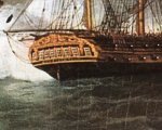
Hy Evans I very much enjoy to read back and forth in your wounderful report here ... Where did you get all that information from concerning the Snodgrass Rudder? I found of course Marquardts remark, but Chapelles is from where? Anyway, while showing the 1803 Cornè (your avatar) to my son, to explain him some of my ideas I accidently picked a zoom onto the rudder and there it was : the hornlike USS Presidents detail ! Thanks for finding such beautiful tiny details, Evans - its such a fun !
- 446 replies
-
- 1
-
-
- Revell
- Constitution
- (and 1 more)
-
Wow that´s amazing! But will you keep both Labels. That way she will lay all her life "clambed" in between those white "icebergs" to lar- and starboard?? Anyway - at least these are not labels of that satanic perdition called "RUM" so many sailors ruined their bodies and souls with ....
- 71 replies
-
- 7
-
-
- pirate ship
- bottle
- (and 1 more)
-
wow - I am fascinated following this interesting "little" project. A really phantastic bottle-ship, very well presented. Looking forward to see it in place!
- 71 replies
-
- 7
-
-
- pirate ship
- bottle
- (and 1 more)
-
Hello Evans, have not been here for a very long time! Beautiful progress!!! .. and wonderful paintings in the Museum you shared with us. Thanks for that! Would you tell us which kind (seize) of eyebolts you used? .. and the deadeyes - from which company are those? They look really phantastic ! Of course I very much like your approach with the rigging. Is the block visible on the Hull Model also used by Erkisson?
- 446 replies
-
- 1
-
-
- Revell
- Constitution
- (and 1 more)
-
Hello Evans, I have one question: what is the book below Chapelles History of American sailing navy?
-
Permission granted to come aboard, Sir? Looking forward to see more ...
- 42 replies
-
- 1
-
-
- Constitution
- Revell
- (and 1 more)
-
Another build, I want to follow. Good luck and have fun!
-
Oh wow .. I missed the start of this build ! Beautiful, a masterpiece ! I will follow your build and I am looking forward seeing your next steps.
-
A BEAUTY !!!
-
Oh wow, I have to follow this build. The Heller kit of Glorieux found luckily ist way via a not very motivated bit in the big bay.. So I first planned to use it as a test and learn build until I noticed the Beauty of those 74s by a El Supremo years ago. So ist still waiting for the time of real start to build models.. not just visiting others reports. Love your one !! Looking Forward to see more.
- 23 replies
-
- 2
-
-
- le superbe
- heller
- (and 1 more)
-
Hello Evans, thanks for the insight! The ship and the museum are a great attraction - to children and adults ! I am so sad to be on the wrong side of the Atlantic not having the possiblity to just pop by .. But one day I will travel to Boston again - this time with my family - and this time during indian summer (which I missed, when I did my internship). I very much would like to show my sons (especially) the hard work of holystoning the decks - this would clean up with some romantic ideas about the life on board ;-) And thanks for the pictures of the paintings .. they missed in my little collection!
-
Wow - the capstan looks marvelous !!! Do you have pictures about how you did this?? Very impressive ! Absolutly cool !
-
What could be added to this? ...Nothing! Fully agree! Well explained. I too very much admire your Research, the way you think and look at information, sources, second sources, etc. .. And I believe that its the responsibilty of a thinking human being to be careful with informations presented by others. Its always of great value, if you try to rethink it. There could be something missed by your predecessor ... Not because you do not trust others. Not because you think you can do better. But just because experience shows - no one is perfect, no one has the single truth. Its a journey to come closer to what we believe to be the truth. But is´nt it fun to go on this journey? I like this a lot! In my future life I would like to become historian. .. But thinking it, I also think: if you have to do it to make your living, fun can dissapear very quick :-) Evan - very interesting thoughts. Tim, very interesting feedback!