
Moonbug
-
Posts
948 -
Joined
-
Last visited
Content Type
Profiles
Forums
Gallery
Events
Everything posted by Moonbug
-
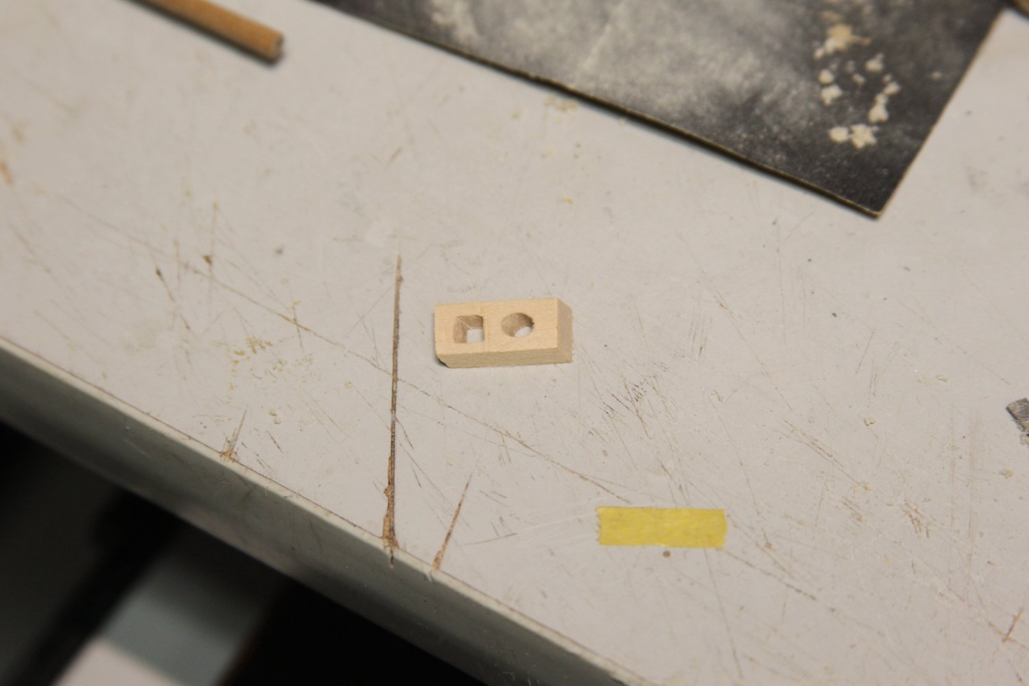
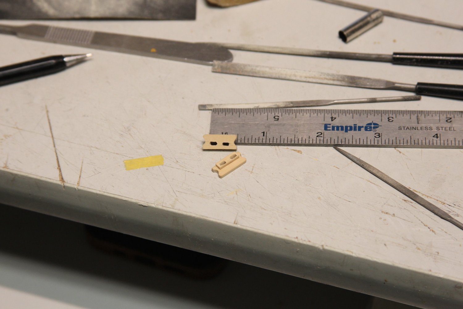
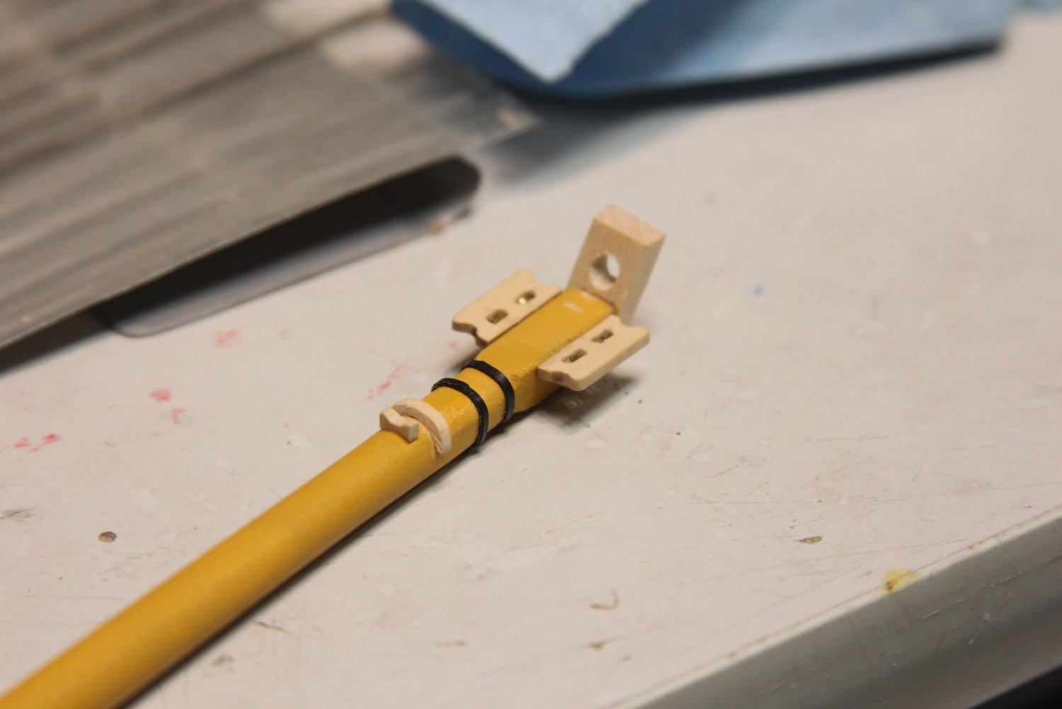
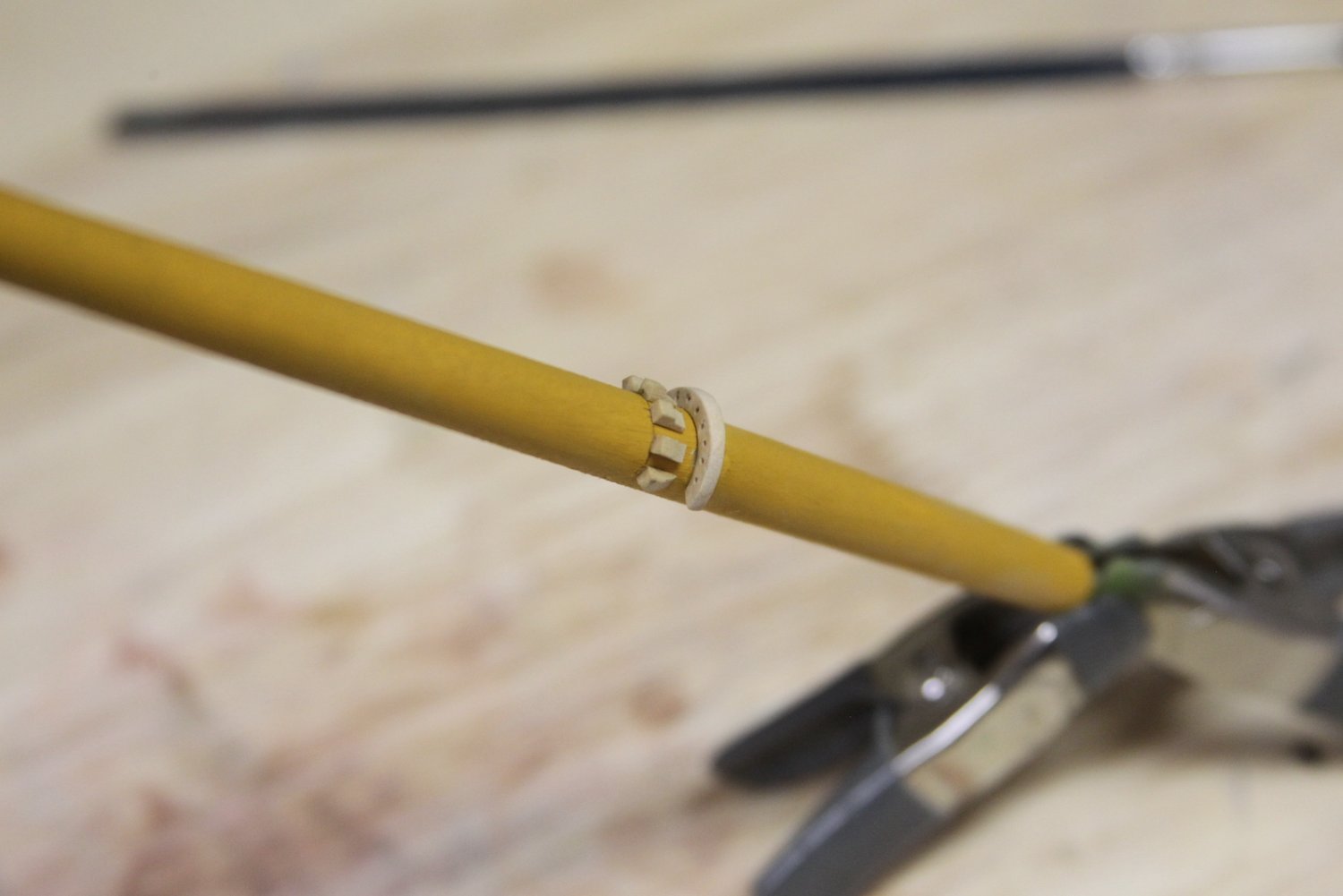
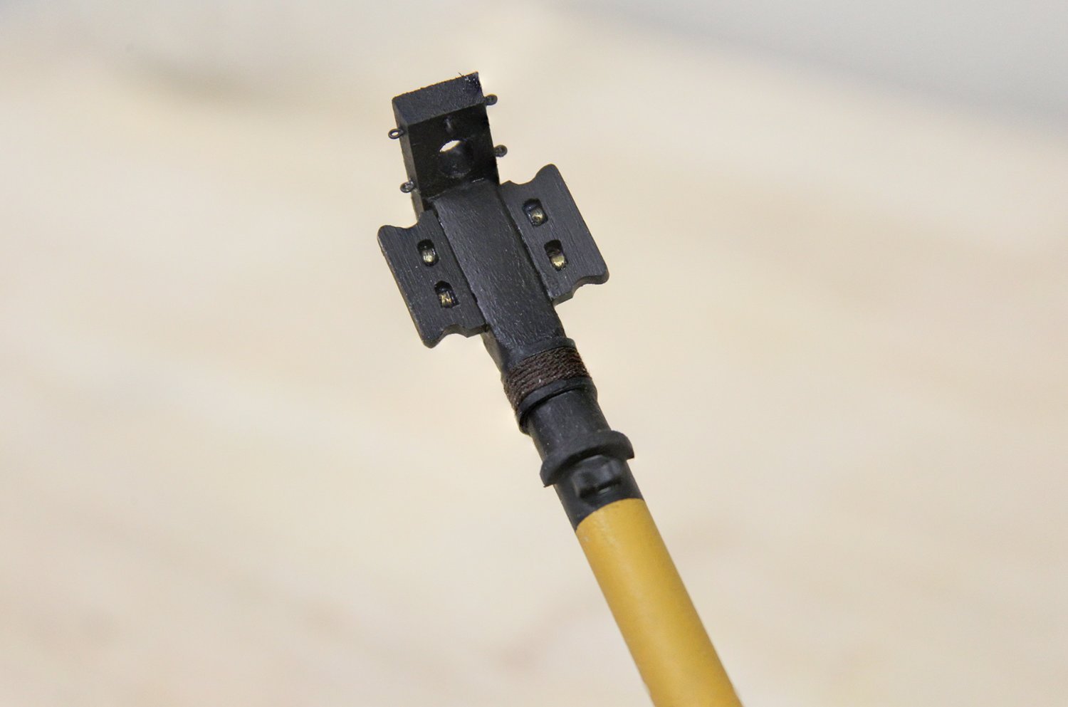
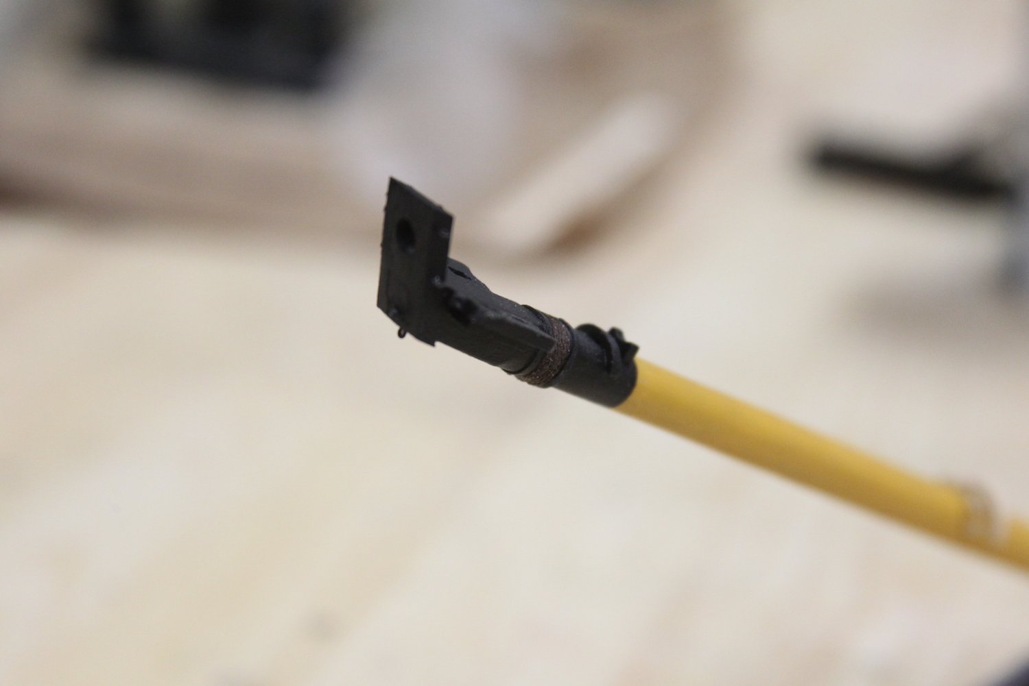
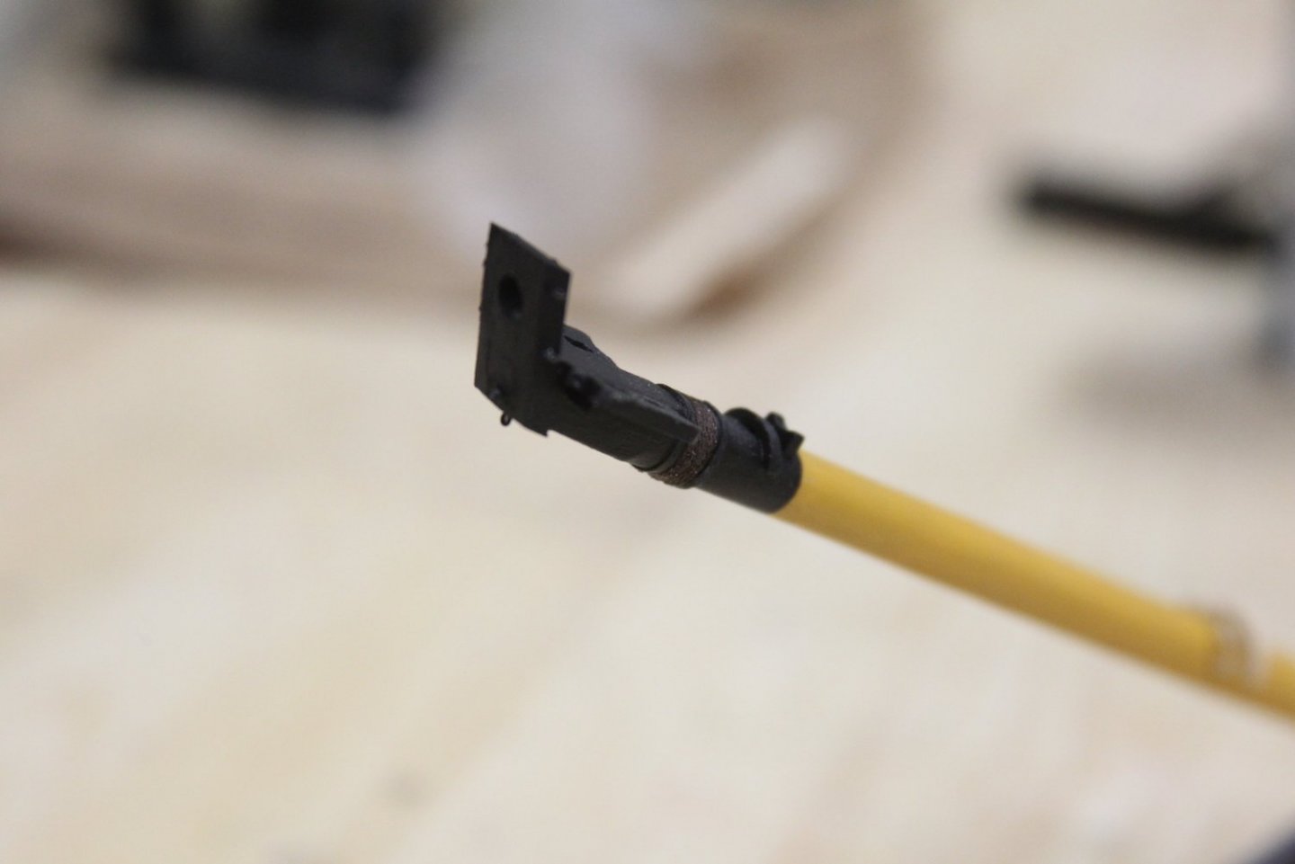
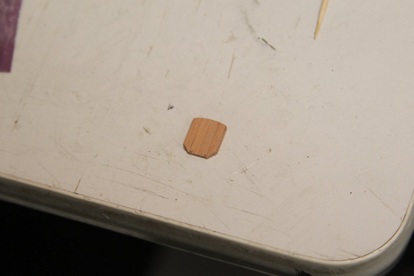
 Thanks @starlight, appreciate it - along with all the looks and likes. Continuing with the bowsprit, had to make my own cap as the kit has a simplified version of this part of the ship to accommodate different skill levels of building. The kit version of the caps has two circular holes, as the bowsprit is simply tapered along with the jib boom. This cap is pretty finicky to make as all the entry/exit angles must be exact. I measured a 4mm dowel as a temporary jib boom to ensure placement and fit is correct. I used basswood for this piece as it'll be painted and doesn't require fine cutting or sanding. I used boxwood for the bees and bee blocks however, as they DO need fine cutting and sanding. I used my usual technique for creating the sheaves. Likewise used boxwood for the sling cleat and jib boom saddle. For the woolding I used sliced pieces of electrical tape before wrapping the line. The electrical tape has some stretch to it, allowing me to layer it while still ensuring that it's even. The saddle and gammoning cleats are also shaped from boxwood and mounted. After everything is added to the bowsprit, it's painted black, fashioned with the necessary eyebolts and woolding wrapping, then given a coat of wipe on poly.


- 323 replies
-
- 11
-

-
- Victory Models
- Pegasus
- (and 3 more)
-
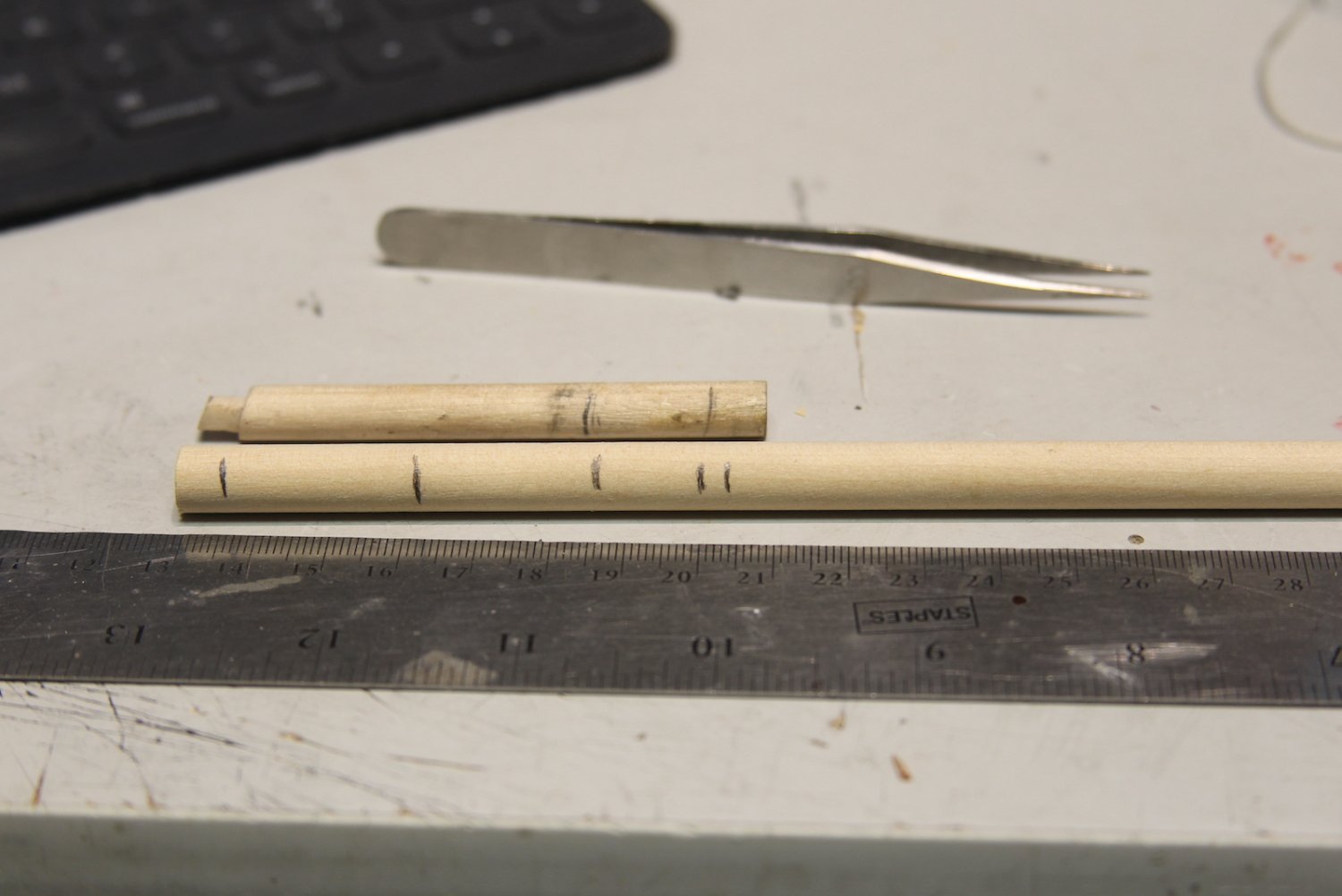
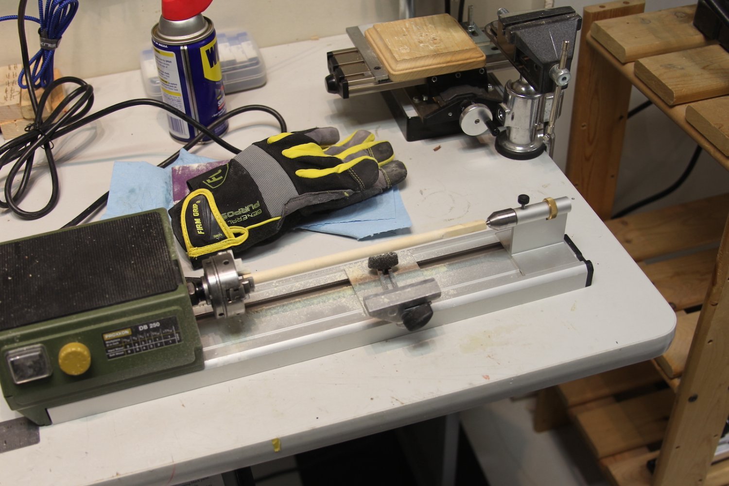
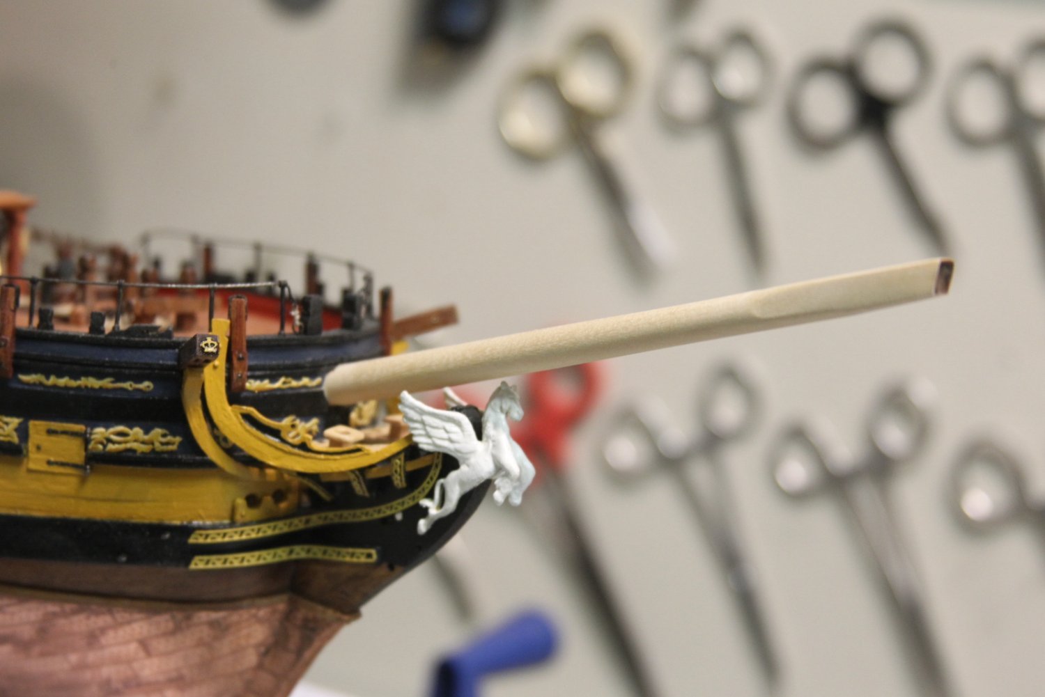
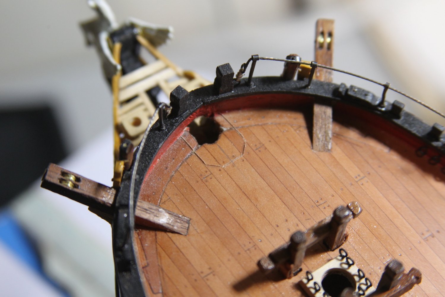
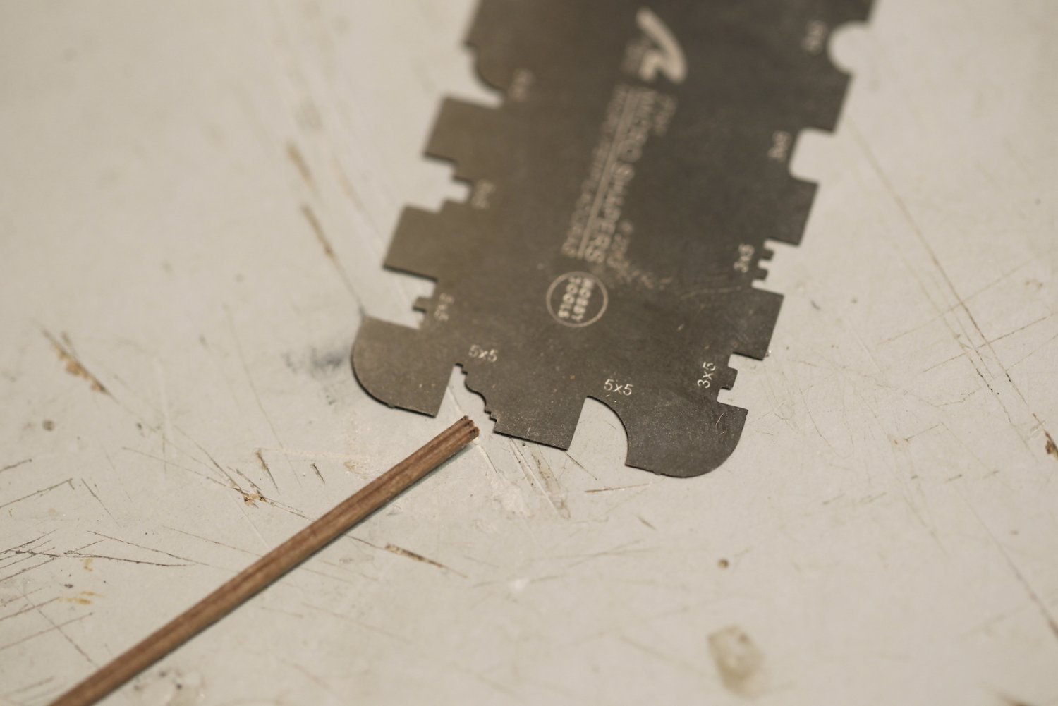
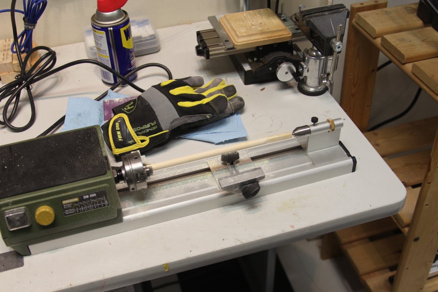
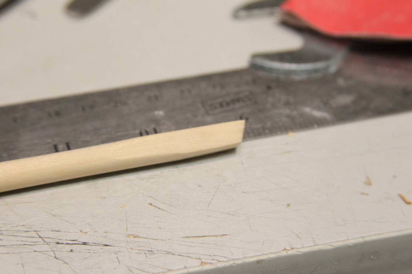
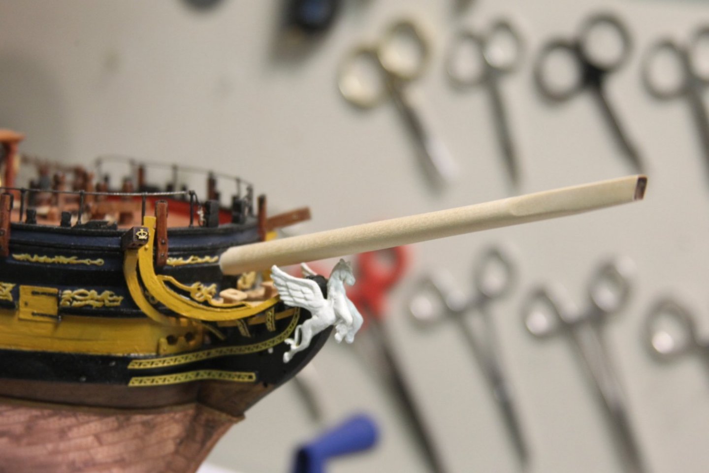
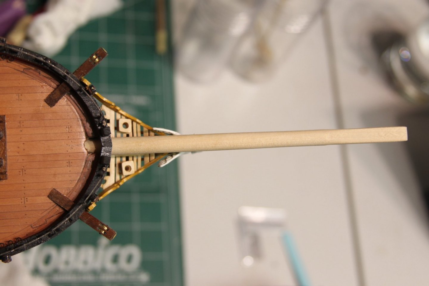
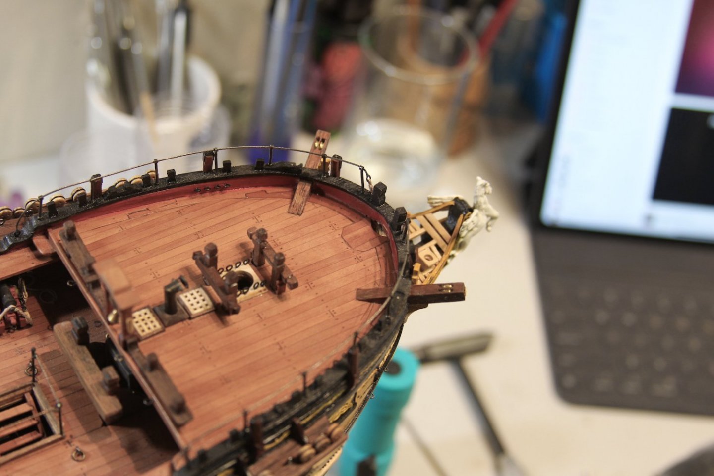
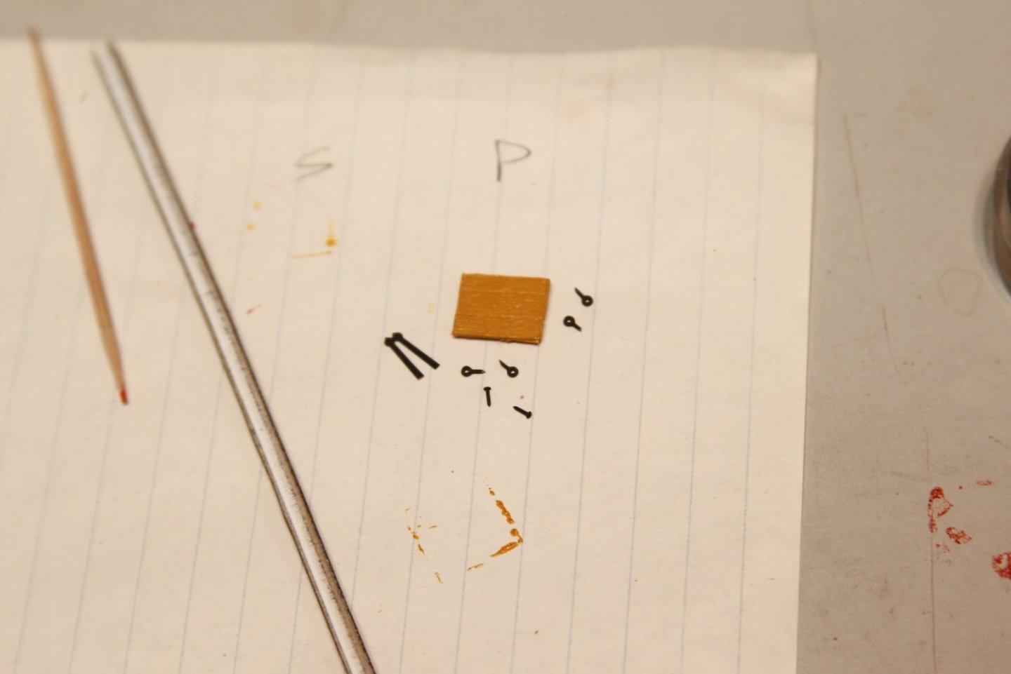
This weekend I started on the bow and the bowsprit. I am modeling this work on the TFFM images rather than the ship plans. First steps were to take my bowsprit "nub" that I've had in place and take some measurements. Obviously the plan lengths won't work because my bowsprit extends on to the main deck and into the support. The marks below represent the notch into the support, how far it extends inboard from the knightheads, then I marked where the gammoning will wrap. That allowed me to then line up with the plans to determine the overall length. Based on the plans, I am tapering the diameter of the bowsprit at 8mm in the middle and 7mm as it enters the bow and as it reaches the square fore end where the bees will attach. I squared off that end of the bowsprit first, then tapered the rest on the lathe - test fitting until it slid in smoothly. Once I had the length proper, I notched out the aft end so it would sit in the step. And interesting note here: On the TFFM plans - as well as some other Swan Class builds - the bowsprit should sit on the saddle were the headworks comes together. However, on nearly all the Pegasus builds I've seen (including mine) there is a distinct gap between the bowsprit, saddle, and figurehead. A first this bothered me, but the bowsprit will be gammoned tightly and it should be an issue. After the bowsprit is temporarily fitted - I moved on to finally adding the bowsprit partner. I fashioned it from planks of Swiss Pear so it would have the same look/feel as the deck and shaped it similarly to Dan's Vulture. I cut out the space for it, then added it in place. Yes - I understand there are a couple of anomalies here in terms of accuracy - first that the partner would most likely have been a single piece rather than planks glued together as I have it - but I'm pretty much out of Swiss Pear, so I'm adapting; and I didn't want to use a color wood that was vastly disparate. Second: The way this kit/build is engineered, the bowsprit does not overlap and insert into the upper deck quite as it should, so the partner is essentially useless. I also understand that most of this is obscured by the breast hook which was made next. The breast hook was also made from Swiss Pear after the shape is measured with card stock. As I said above - I'm running low on Swiss pear so I stacked and glued a couple of pieces to create the proper thickness. The breast hook is then shaped and mounted with 'bolts' in the front. Finally, I carved out some small cleats that are mounted parallel to the bow's rail as laid out in my TFFM photos. I carved these out of boxwood using a couple of different Dremel attachments and some light hand sanding.


- 323 replies
-
- 11
-
-
- Victory Models
- Pegasus
- (and 3 more)
-
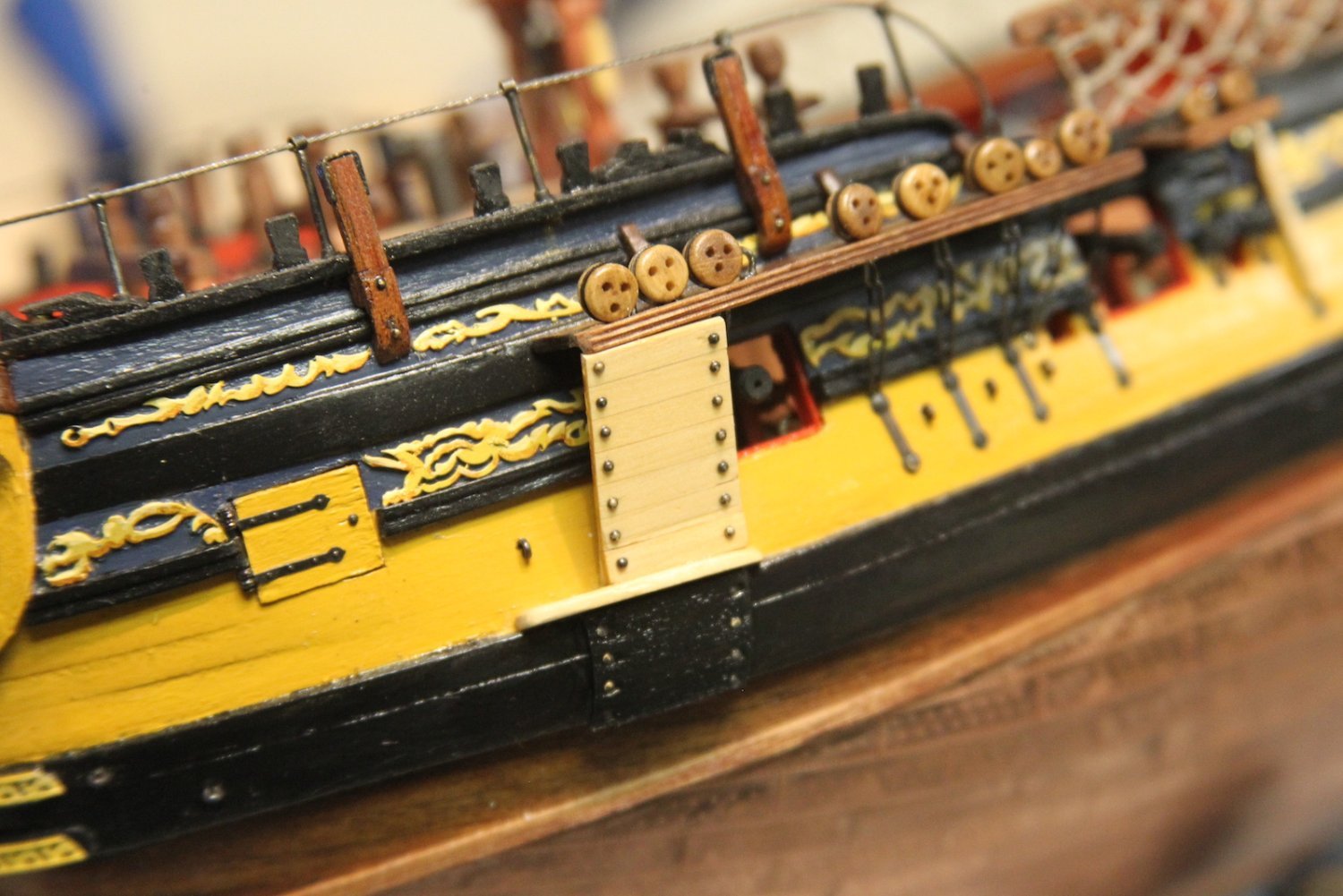
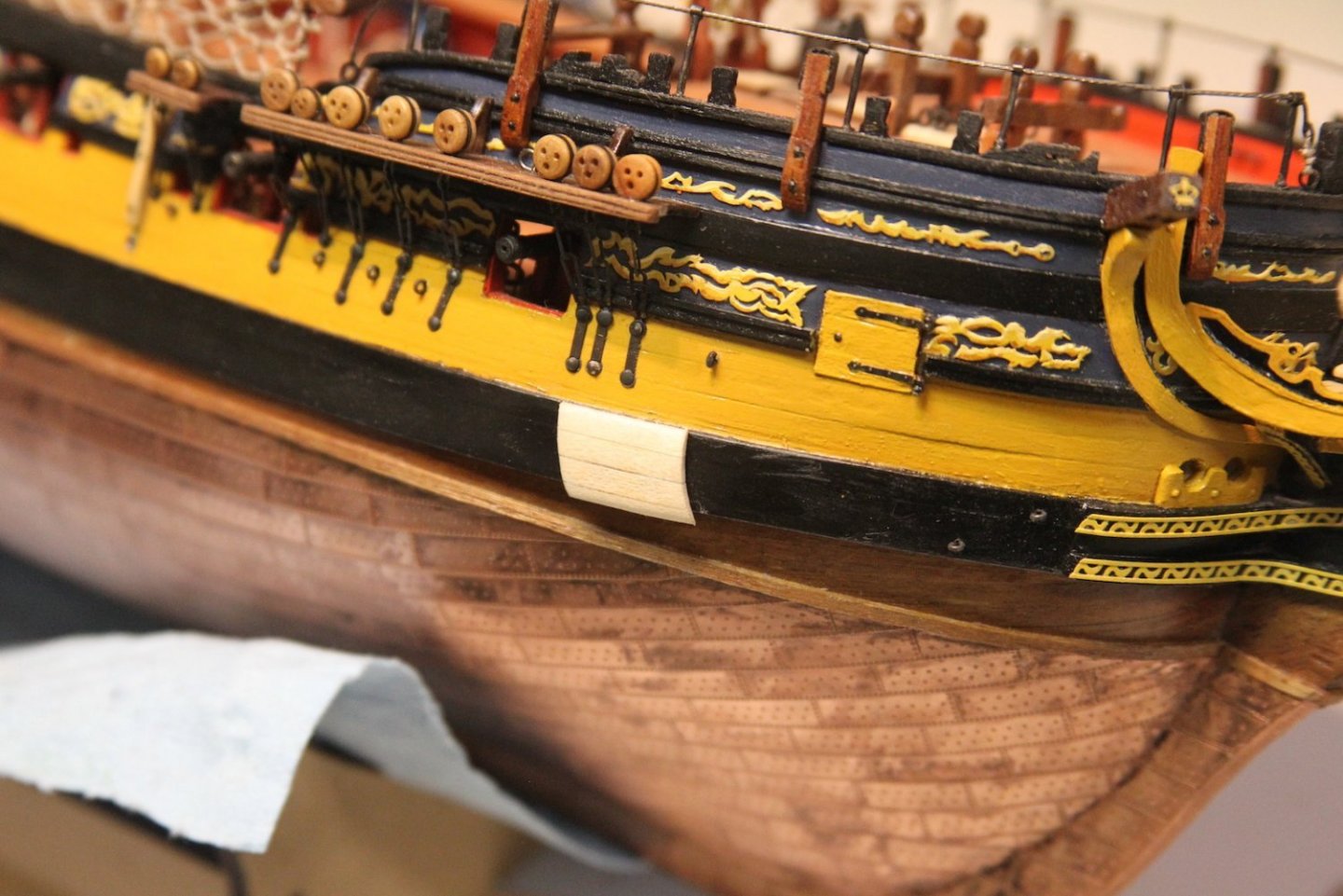
Though I haven't had as much time to work on the Peg as I'd like, I did manage to get the billboards up. I used 1/16" x 1/8" strips of basswood for the portion that covers the wales since it's going to be painted as well. However, I used boxwood for the bolster just below the chains plates, the upright stanchions (1/16" x 1/16") and planks (1/16" x 1/8") so that they would match the other hull fixtures (such as the fenders, etc) once coated with wipe on poly. Final touches are the blackened bolts.


- 323 replies
-
- 10
-
-
- Victory Models
- Pegasus
- (and 3 more)
-
That's been the case around here for quite a while, and I'm sure not uncommon amongst this lot. Heh.
- 323 replies
-
- 3
-
-
- Victory Models
- Pegasus
- (and 3 more)
-
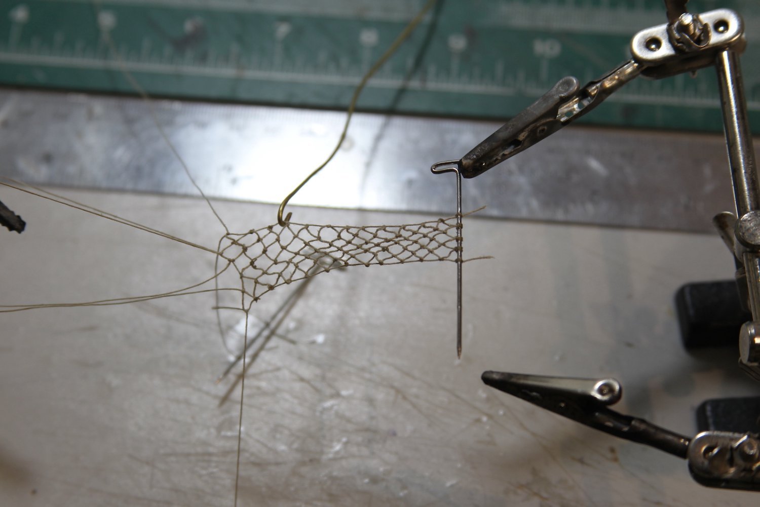
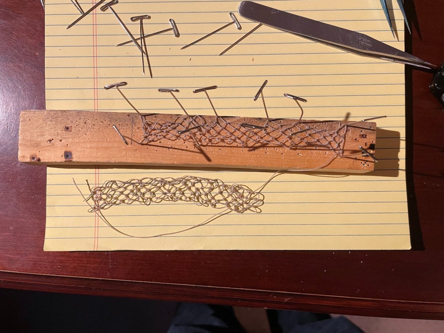
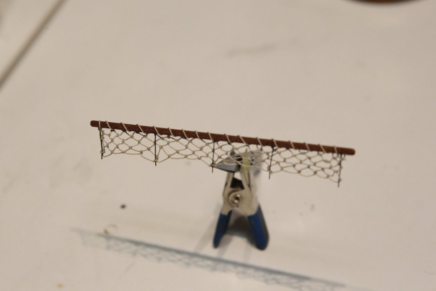
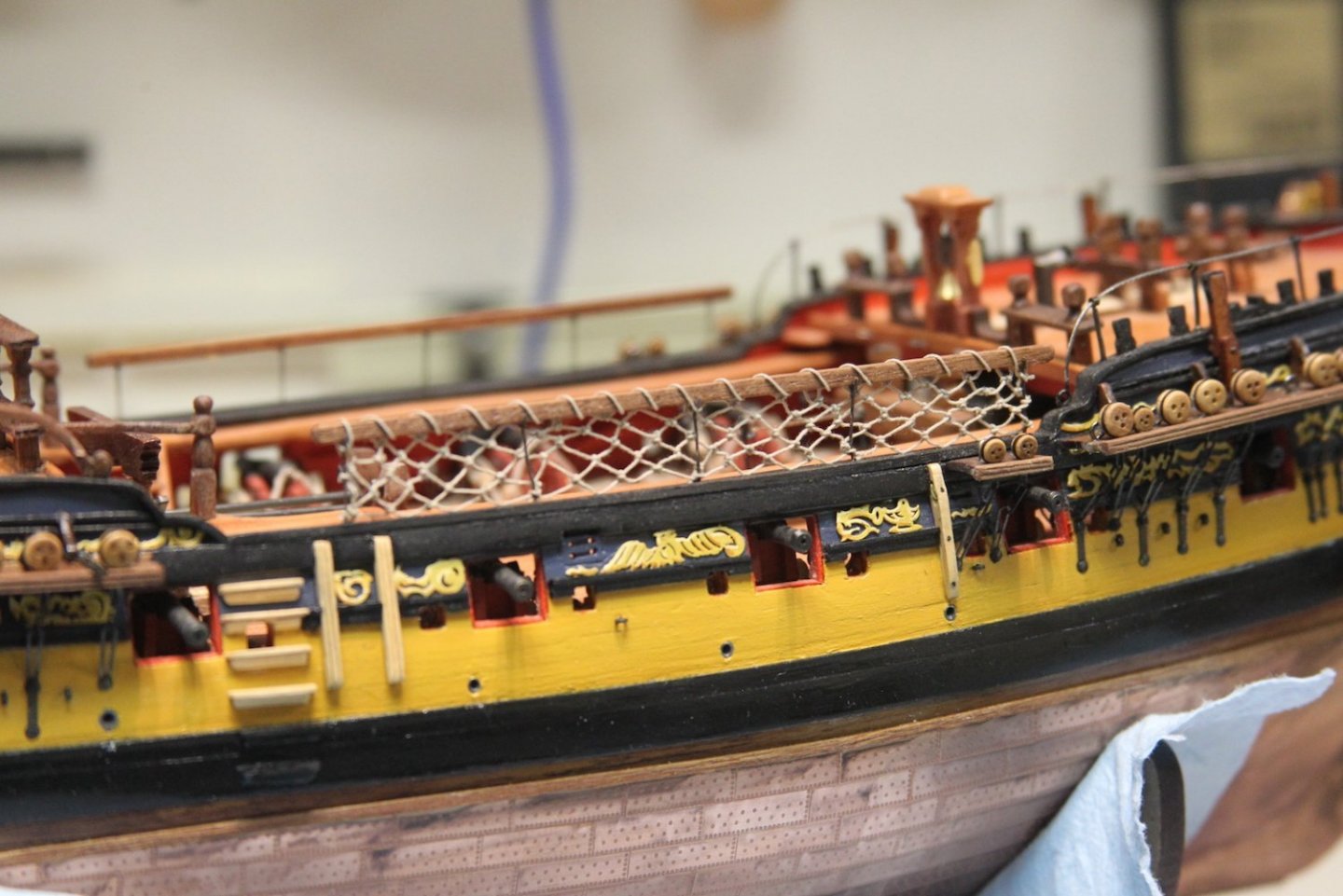
This is one of those short updates that represents a bunch of work. I've been noodling through how to make the netting along the waist rail. I spent quite a while looking for a good "fishnet" representation - even going so far as to ask the admiral if she had any 'delicates' lying about that were no longer in use 😉. I found a couple of 'acceptable' options at a fabric store, but nothing that I was really happy with. None of them looked like "rope" but rather just laced thread. First, I tried weaving together my own netting using Dan Vadas' example from his Jib Net here. Here's my attempt: This is after something like 6 hours mind you, makes tying off ratlines feel like a breeze. After all that, I still wasn't digging it. I think it looks fine - and I may well still use it for a Jib Net, but I didn't like it for the waist. So, after more research I found this guy on youtube. He over explains a bit - which is better than under-explaining I suppose - but more importantly, his method was transferrable to a much smaller scale and I was able to replicate it using .20mm rope. Here's a shot of my first attempt (bottom) which was pretty sketchy, but a good practice to get the hang of it and improve my method. In the top one, I used more pins to hold my tiny work in place and thus create more even loops. I didn't use any sort of net needle, I just used rope with the end stiffened with CA glue. Still took 6 or 7 hours each to complete the netting which ended up being about 113mm long by 11mm wide. I then mounted it to my waist rail by first using a tiny dot of CA glue to attach the loops to the rail and stanchions, then tying off the loops to the stanchions, and finally looping and tying off another length of rope around the rail itself. I've seen other example of this looping on rails in this time frame - usually metal ones to create a better grip on the rail when wet. So I figure it too much of a stretch to have seen it on a waist rail. Finally, it's mounted on the waist. Last touches were to add another tiny drop of CA to hold the bottom loops even with the ship's rail. Overall, this was a boatload of work (no pun intended) for a relatively small area and detail; and I still have the port side to do. I think it's still a touch out of scale (especially the knots), but it's about as small a rope as I could go and still successfully work with. But I'm much more pleased with this than I think I would be with a more modern alternative to netting.

- 323 replies
-
- 11
-
-

-
- Victory Models
- Pegasus
- (and 3 more)
-
Thanks @Techtonic, thanks for letting me know! I may have to give them a try. It’s nice to have another option besides the infamous Amati crew. Be sure and post pictures of your fellas when they’re painted.
- 323 replies
-
- 2
-
-
- Victory Models
- Pegasus
- (and 3 more)
-
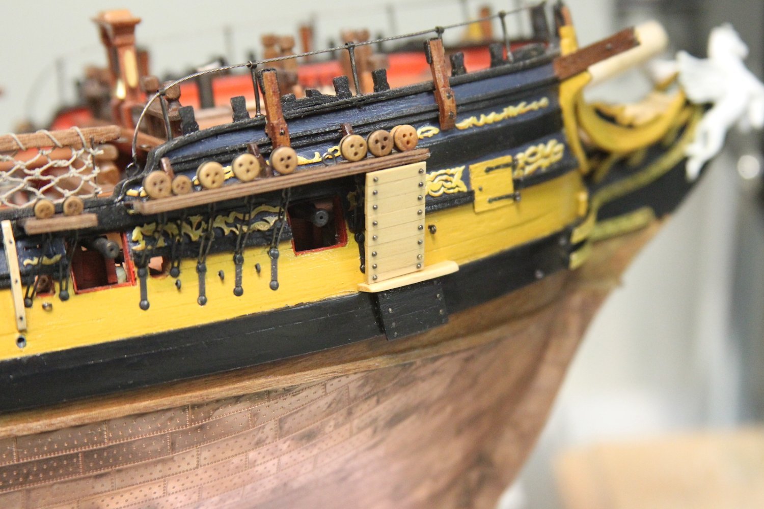
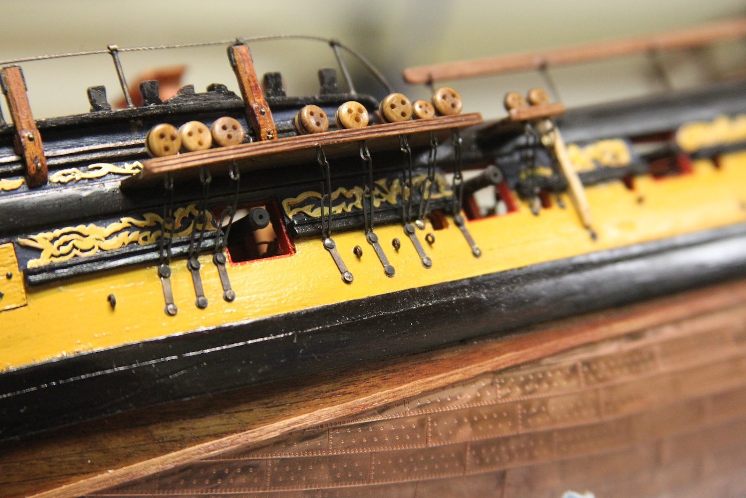
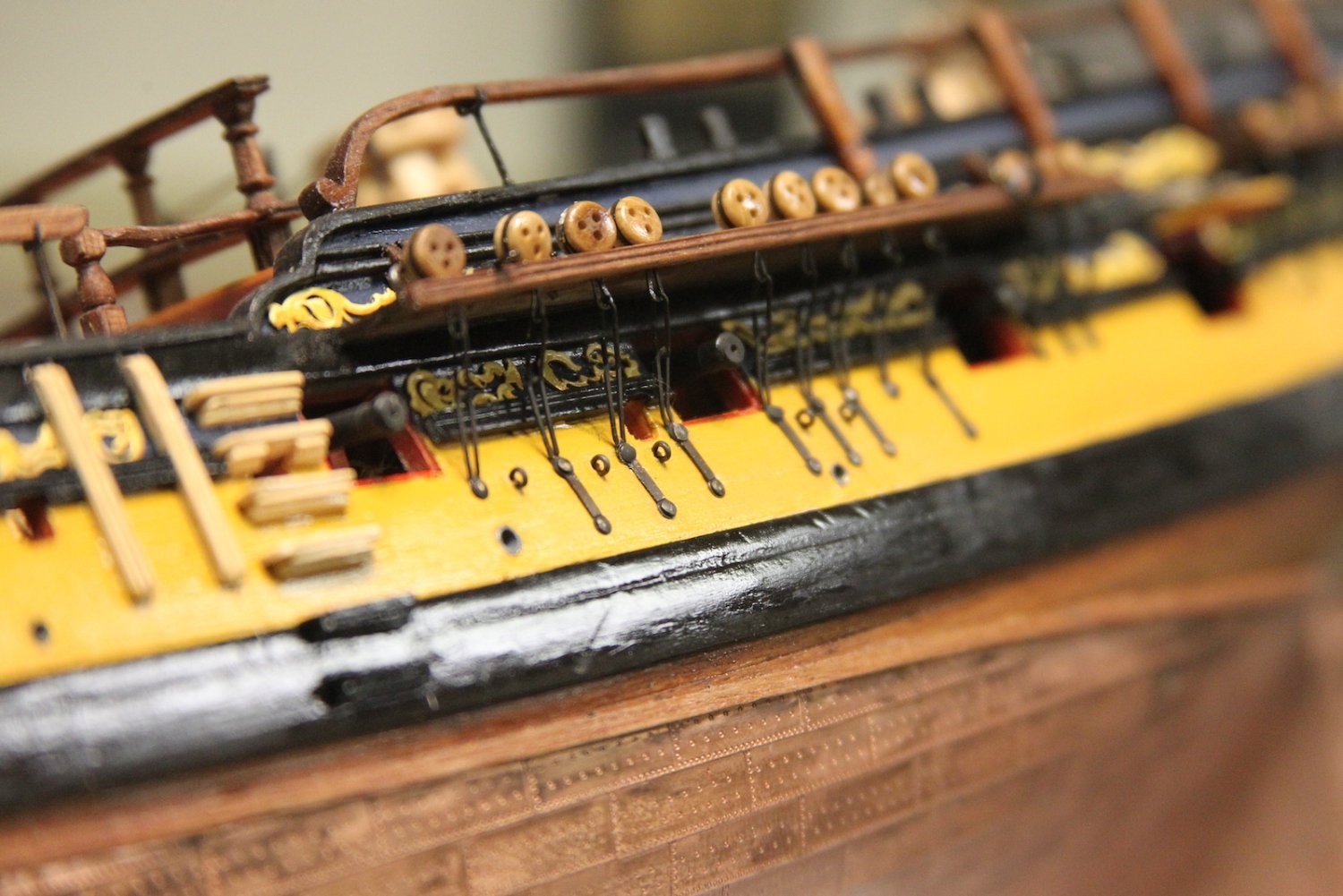
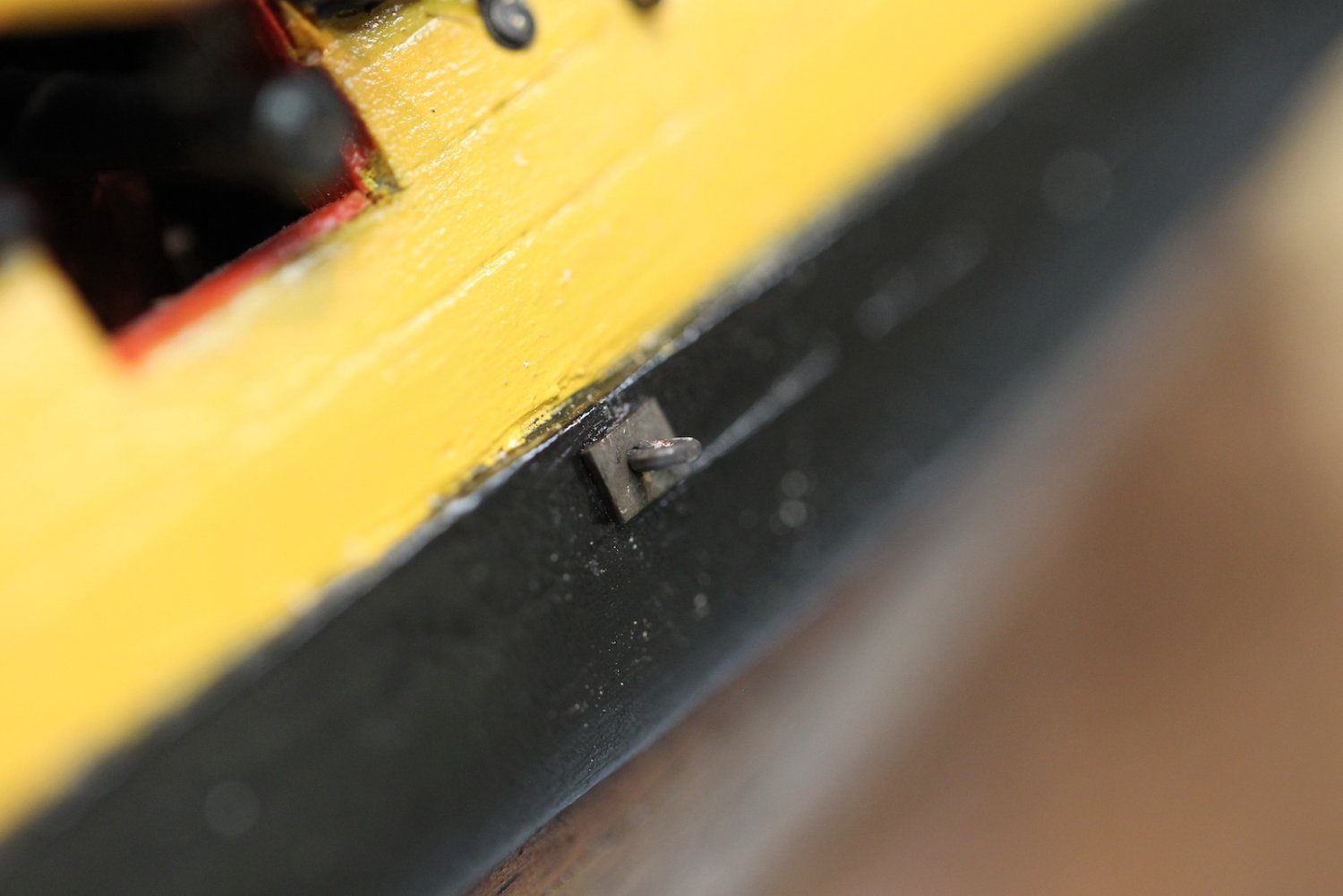
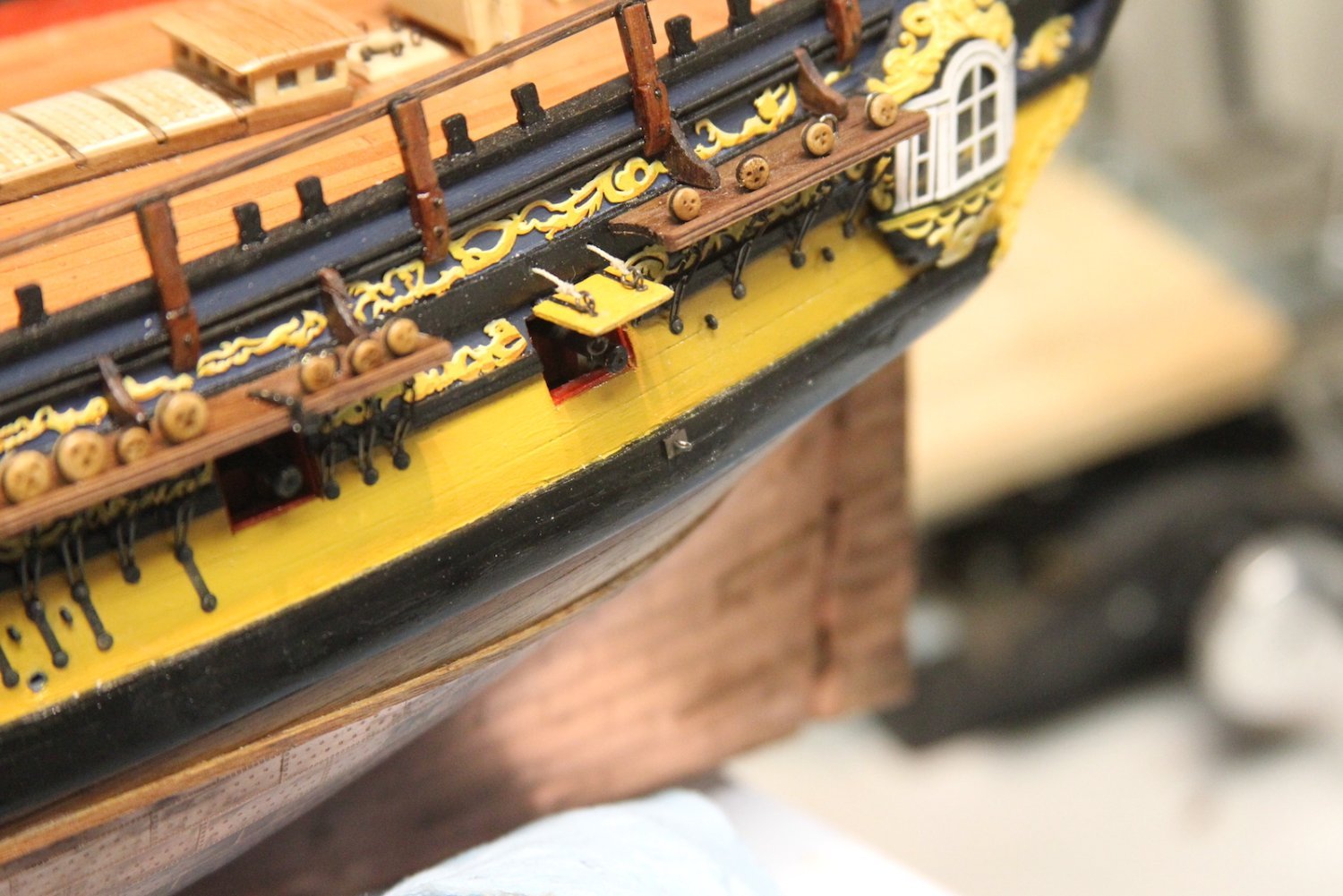
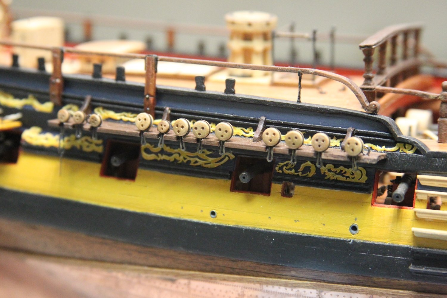
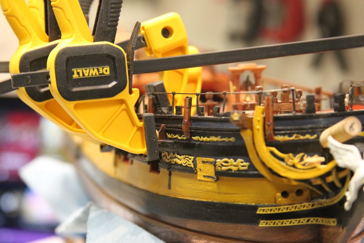
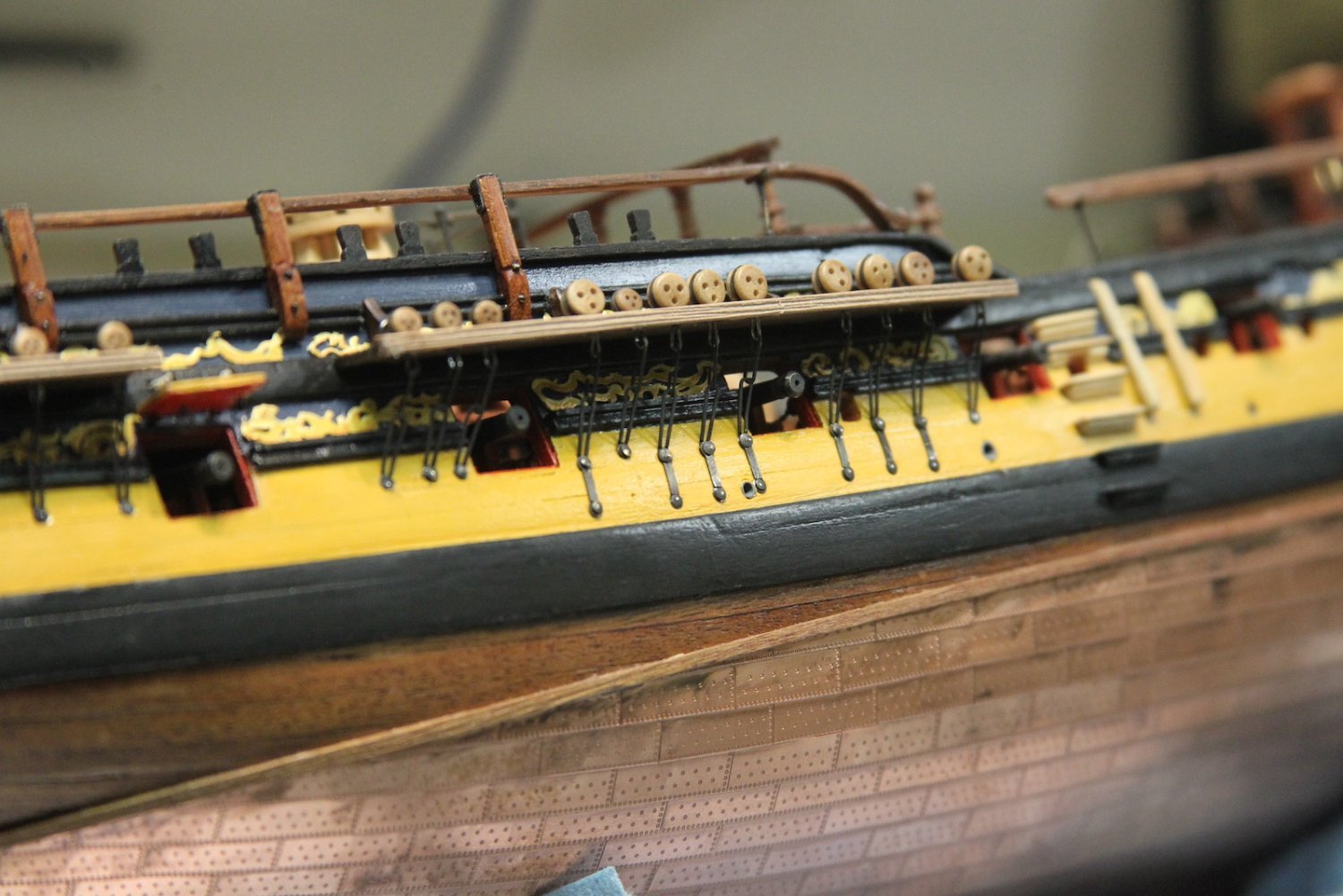
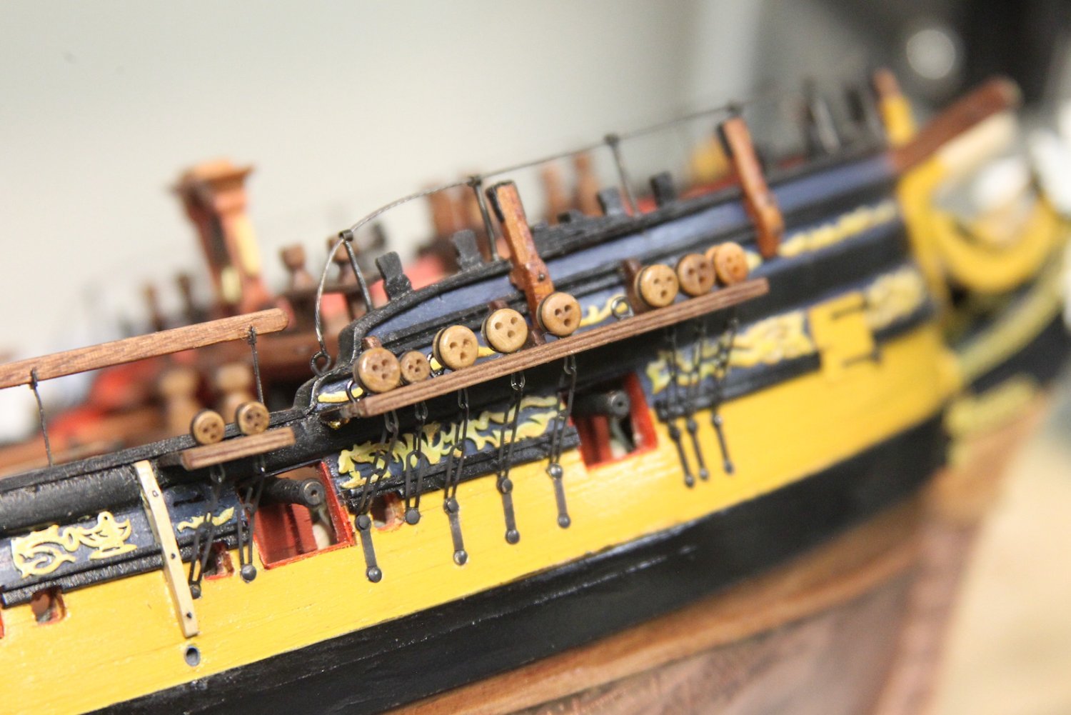
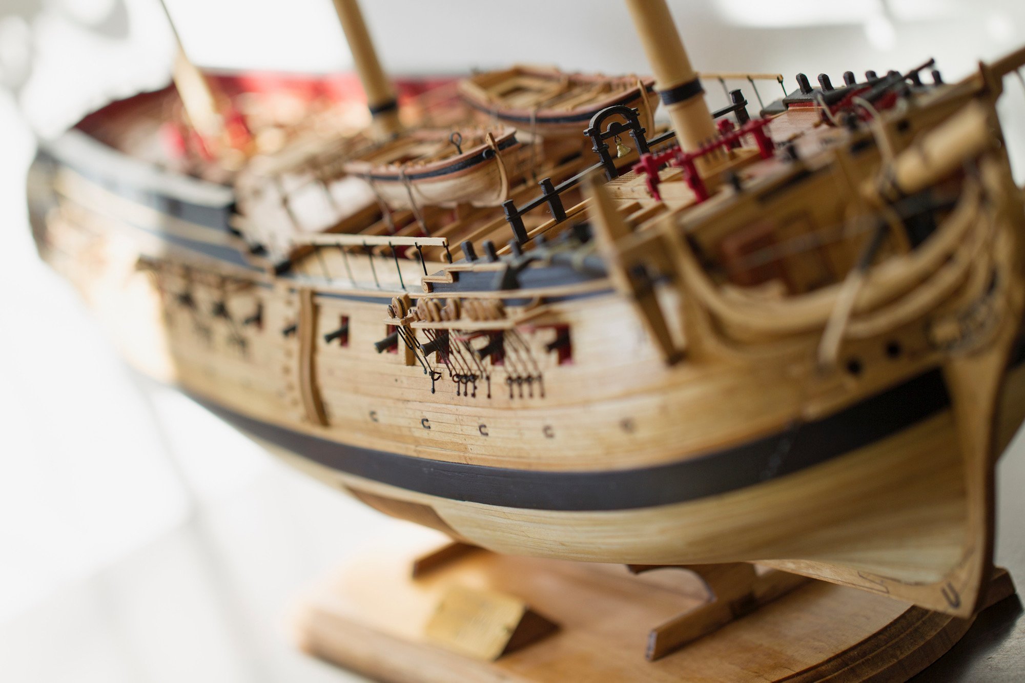
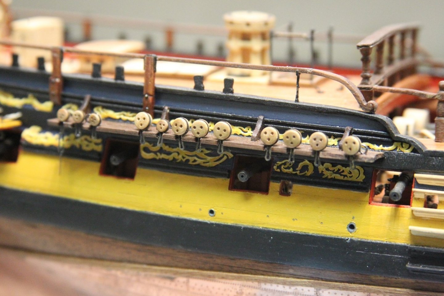
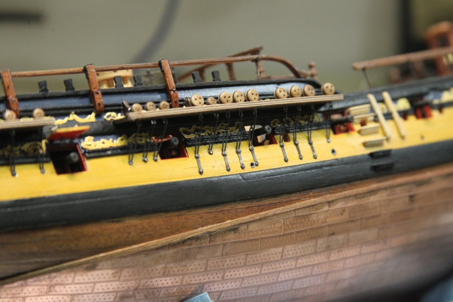
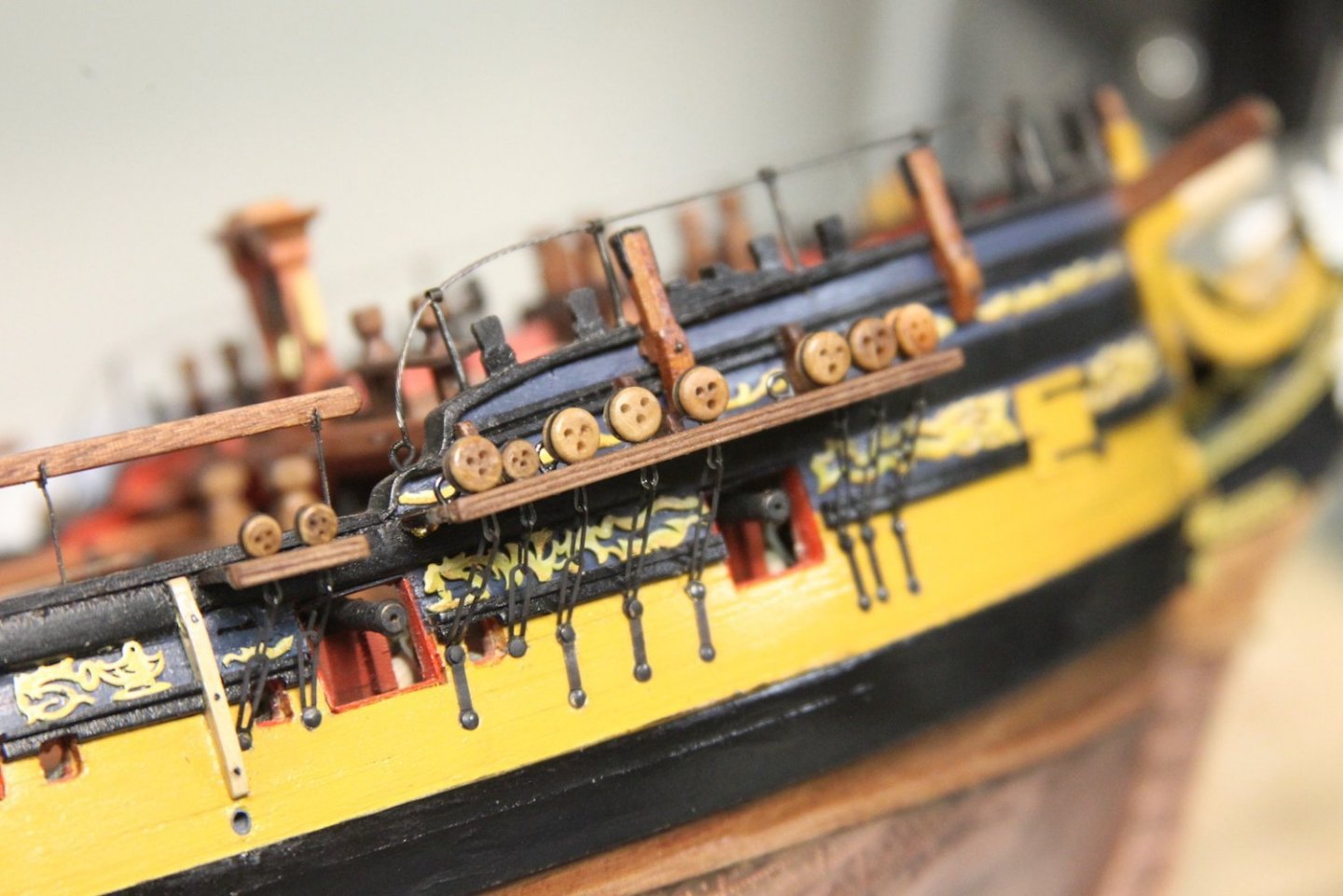
I spent today working on netting for the waist rails - I took a few pictures but in a bonehead move, did not have a card in my camera. Enh. Not sure I'm liking how it's turning out anyway. The rest the day was spent adding 30-something preventer bolts along the chains, and a couple of swivel bolts toward the aft of the ship. Preventer bolts were a back up plan to tie off shrouds should failure of the lines occur, or if repairs were needed. I drilled out the holes, added eye bolts, then tapped them in to make them flush with the hull. I used a pointed dental pick to hold them straight whilst I tapped them in. It's also worth noting that the two in the waist are fixed horizontally, while those in between preventer plates are vertical. The swivel bolts are a just a couple of eyebolts mounted to a plate then blackened before mounted in the main wales just aft of the last gun port. Personally, I think these are the kinds of details that are relatively easy to add, and yet add a lot of authenticity to the build.


- 323 replies
-
- 13
-
-
- Victory Models
- Pegasus
- (and 3 more)
-
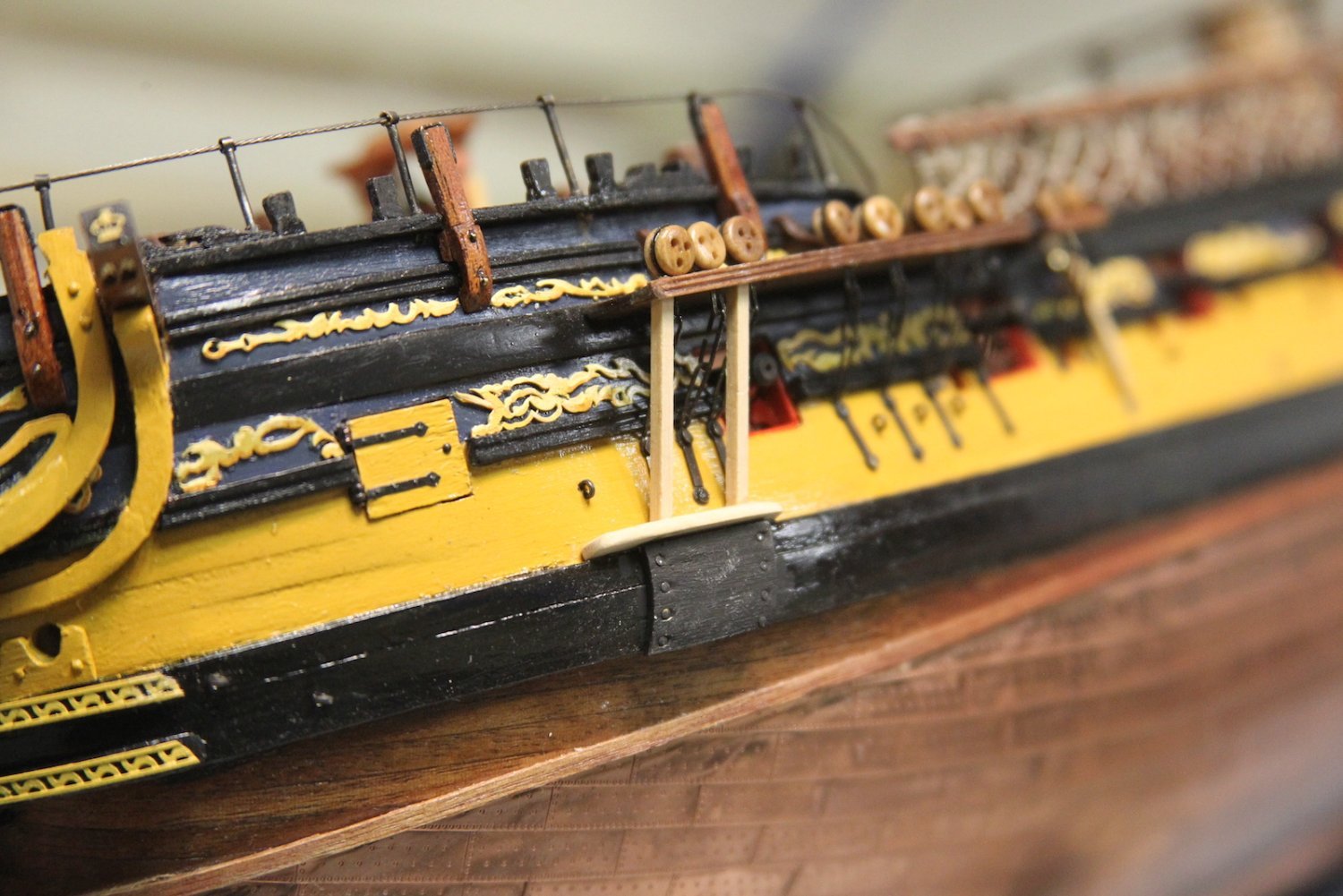
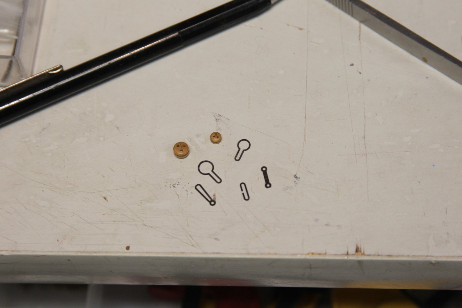
I nocked out a quick waist rail and mounted it using the stanchions that the kit sets aside for the mast tops. Worked on the assembly line of deadeyes, stops, chains, and preventer plates the last couple of days. As others have remarked, the photo etched parts provided are quite easy to work with. I briefly considered soldering closed the chains, but they are barely (if at all) visible on back side so I left them as-is. It's worth noting that while I did my best to consider the lines of the shrouds when lining up all the chains and preventer plates; some adjustments had to be made for the gun ports, sweep ports, and even a couple scuppers. I also used slightly larger pins/nails as they needed to be functional as well as decorative. Once the deadeyes and chains were in place, the channels were capped with a thin strip of walnut scraped with a corner portion of one of the AL scraper edges. Lastly, I soldered and shaped studding sail boom irons. I'll likely add the stun'sl boom later.


- 323 replies
-
- 11
-
-
- Victory Models
- Pegasus
- (and 3 more)
-
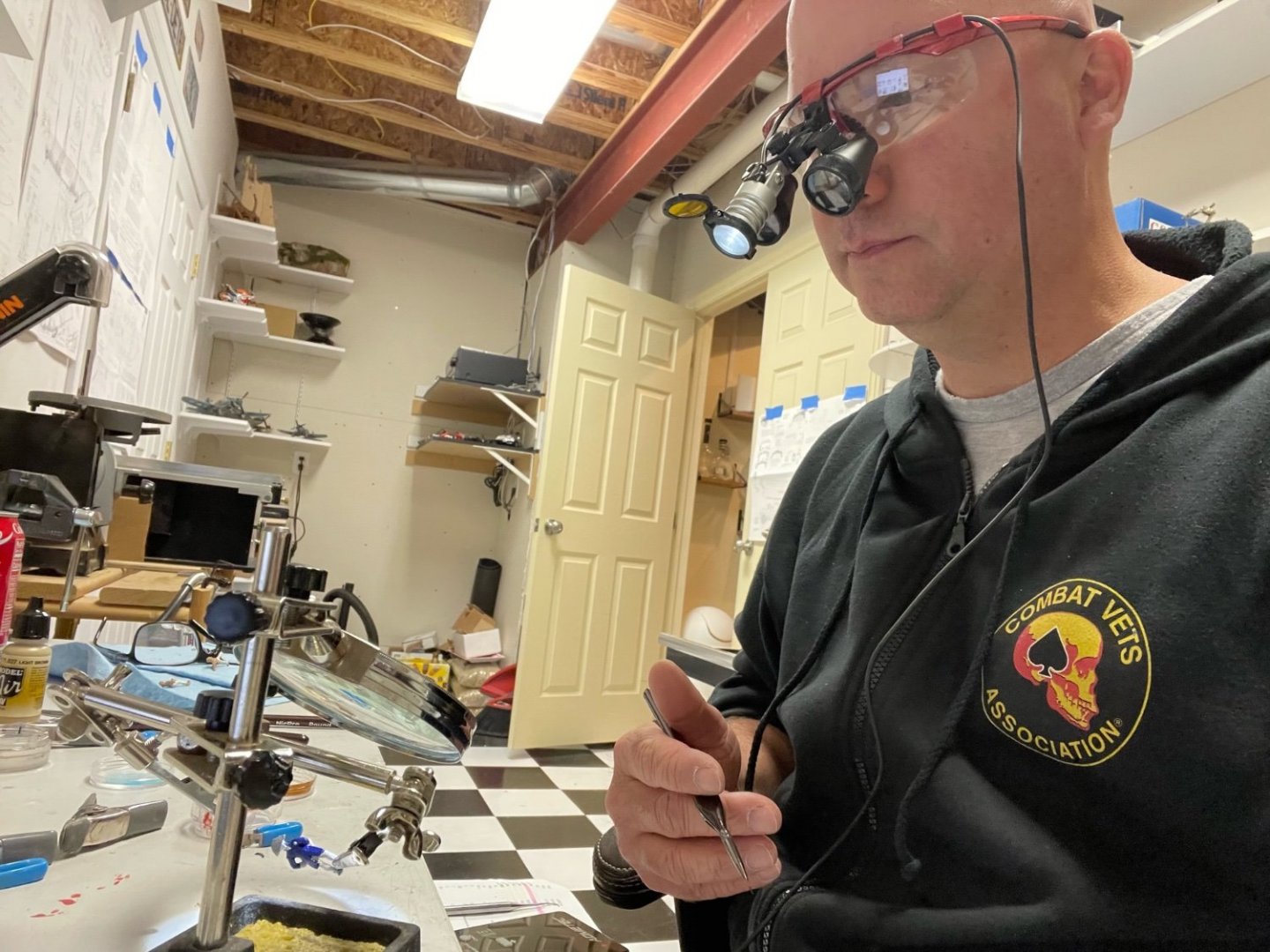
Hey Dave, that's a good question - short answer is yes. Here's a picture my youngest daughter took to make fun of me while I was painting the little Captain Amati. Last year I got laser eye surgery, which works great for everything except extremely close up work. Even with varying levels of reading glasses I struggled with the ultra tiny things. A month or so ago I invested in dental/surgical loupes, and that's what I use to paint the tiny things. They're damn expensive, and I had to go through a local medical supply company (who may or may not have assumed I was Dr. without me correcting them) and they took forever to arrive, but they're very handy. Sometimes - as in this picture - I use a combination of the loupes and the magnifying lens. The brushes are a set of NicPro fine detail brushes, which work well - but I suspect the Tamiya ones might be better.
- 323 replies
-
- 5
-
-
- Victory Models
- Pegasus
- (and 3 more)
-
Thanks BE, appreciated as always. I fretted over the side vs top hinge on the lid for a bit, and ultimately went with the side for a simpler reason: I had more room. Sometimes those decisions are made for us.
- 323 replies
-
- 2
-
-
- Victory Models
- Pegasus
- (and 3 more)
-
I did that once @James H - here in America we call that "a divorce."
-
Wonderful work Mary, worthy of pride.
-
@starlight - you are correct, then bridle port is a fair amount narrower, giving it a much more 'portrait' shape than the rest of the ports. The shape the only difference visually - other differences were in terms of functionality rather than look. As for the other gun port lids, you are spot on there as well. One thing to keep in mind - many fo the kits sacrifice some level of accuracy for ease in terms of mass (or repeated) production. So even kits as well thought out as Chris Watton's, there will always be some simplification for ease of production. In this instance, @Blue Ensign's explanation of how he deviated from the kit is a great resource which explains the difference between the kit and other Six rate ships:
- 323 replies
-
- 4
-
-
- Victory Models
- Pegasus
- (and 3 more)
-
Those cisterns are really nicely cut and put together. Personally, I really enjoyed working through the engineering and mechanics of the cisterns and chain pump assemblies. A very cool part of the ship.
- 858 replies
-
- 3
-
-

-
- Sphinx
- Vanguard Models
- (and 1 more)
-
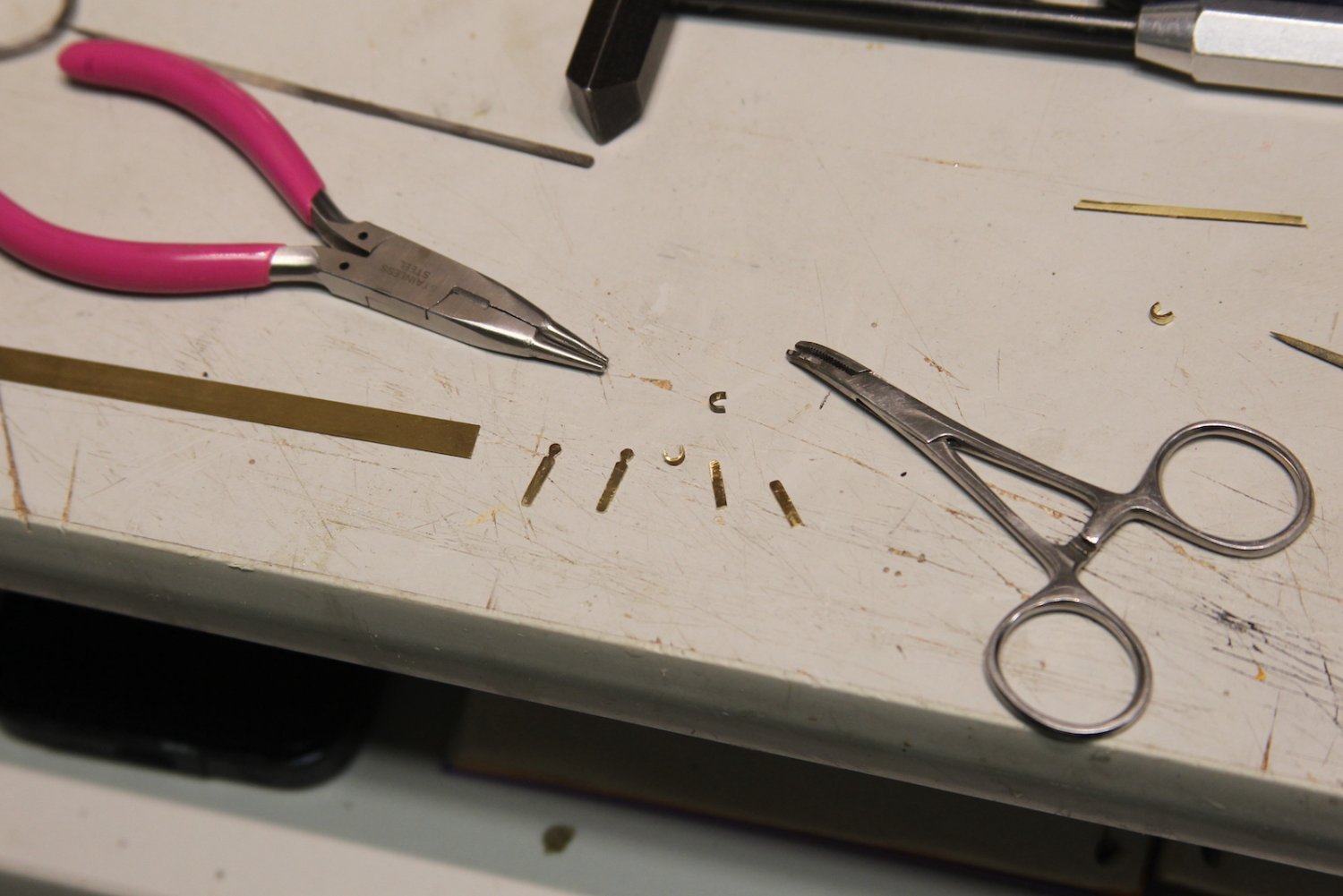
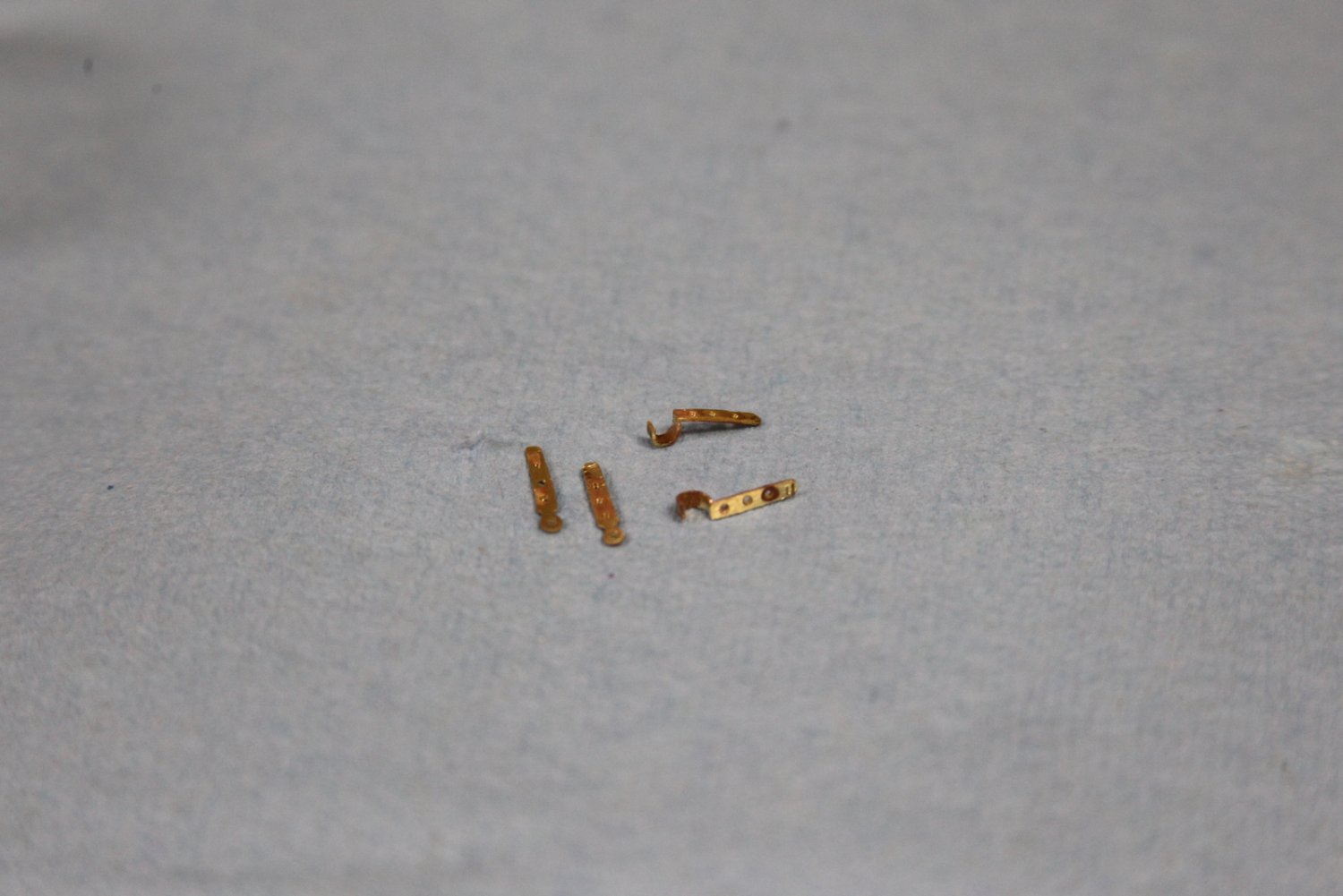
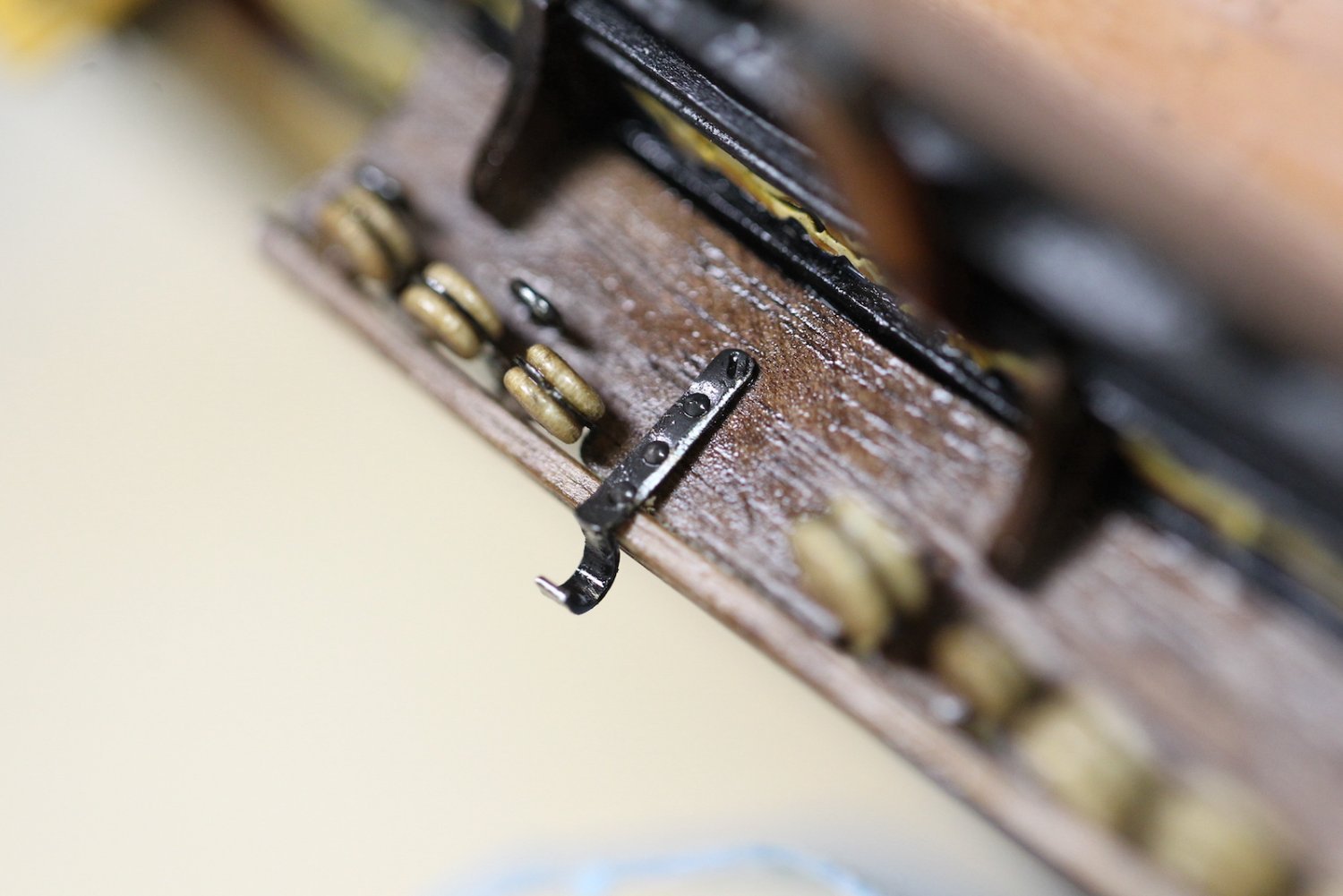
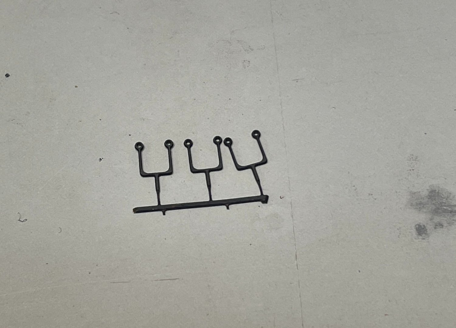
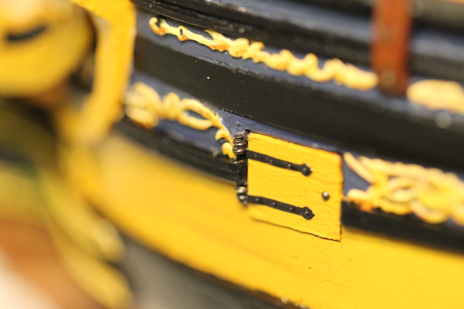
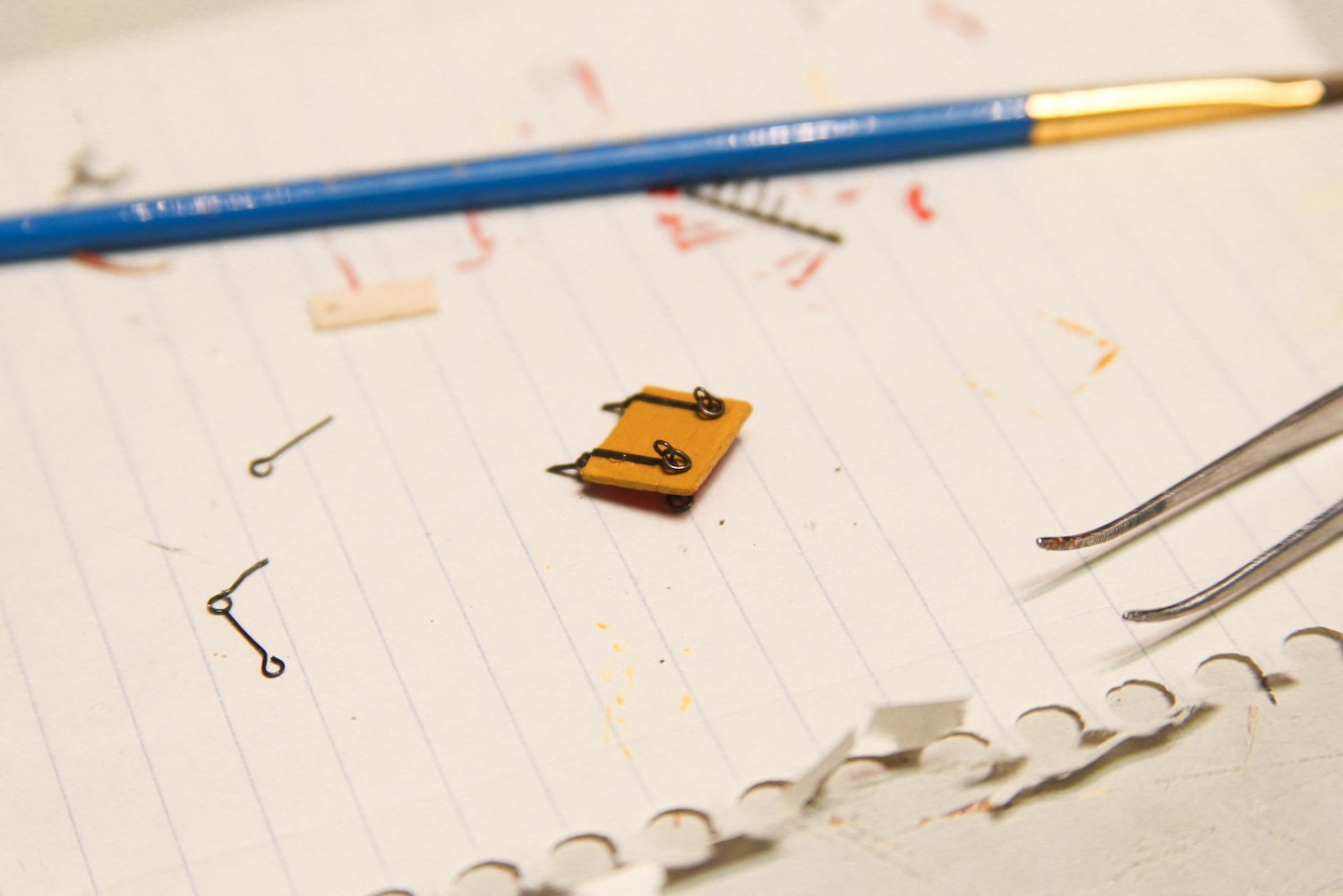
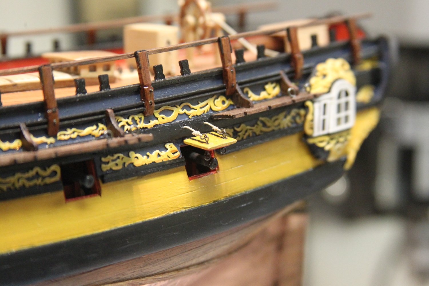
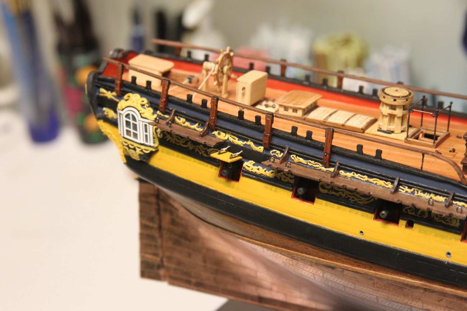
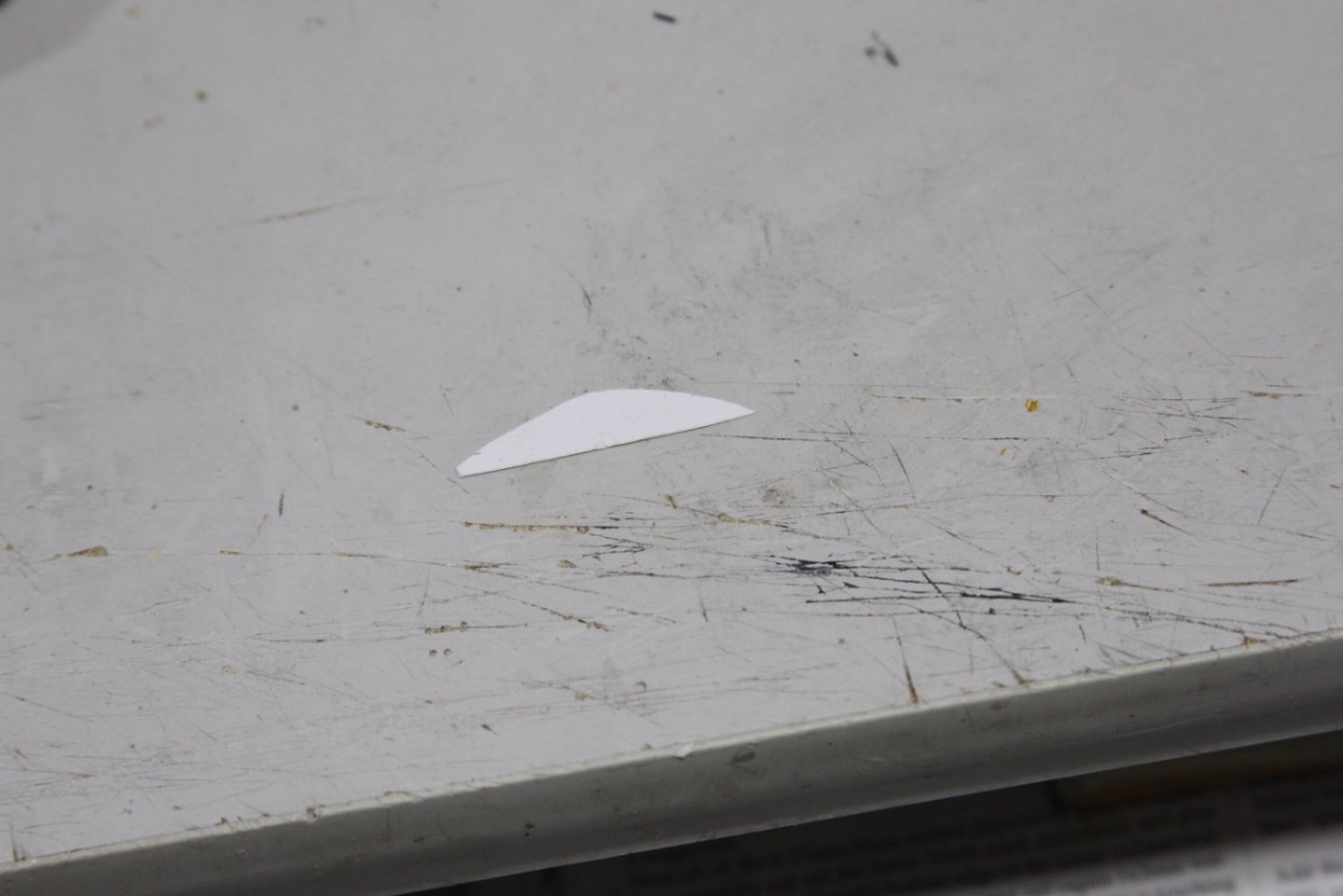
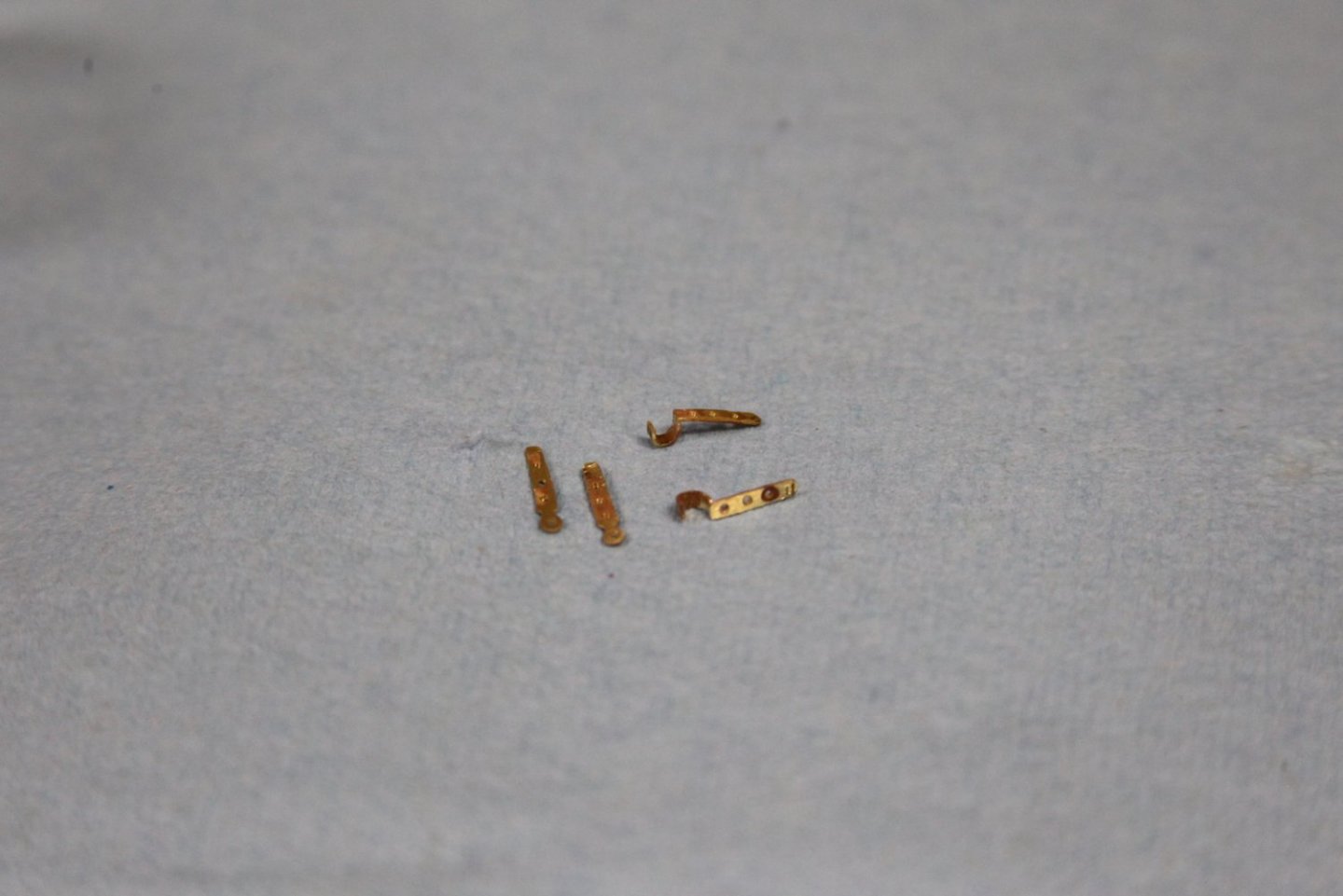
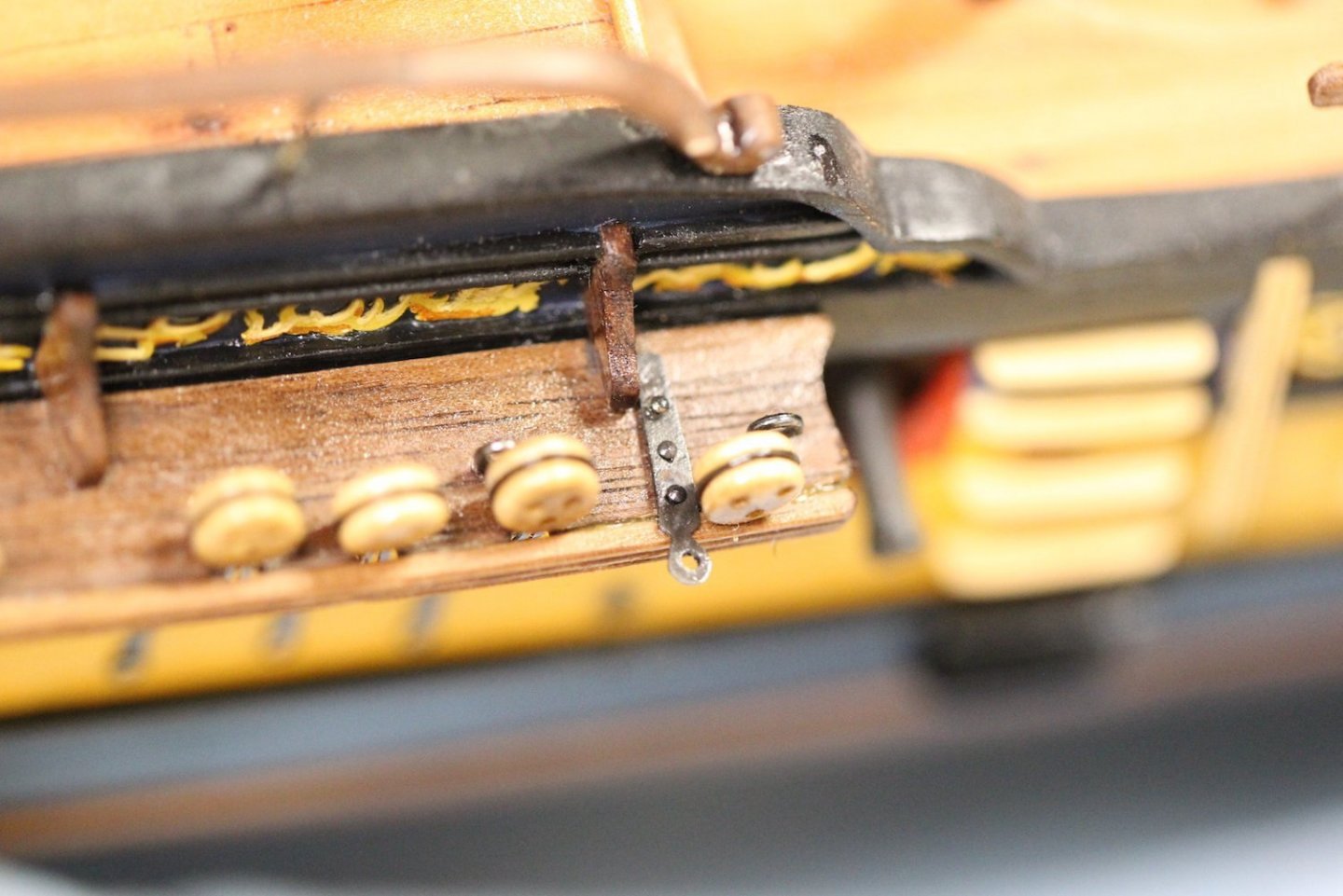
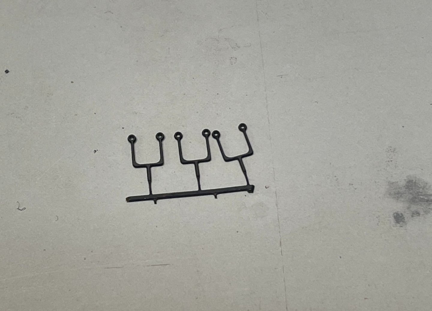
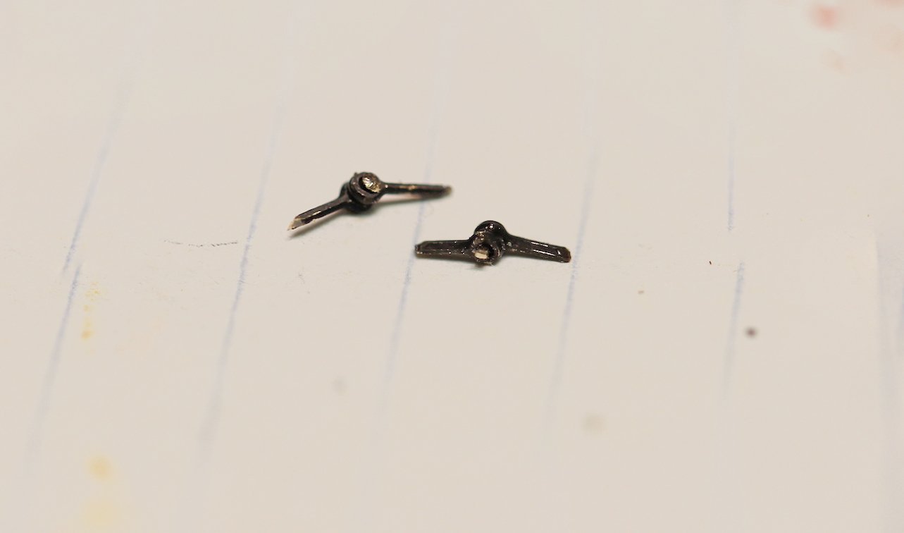
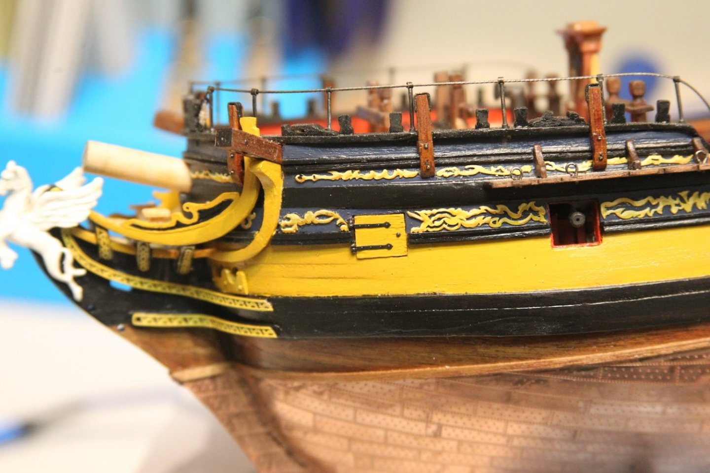
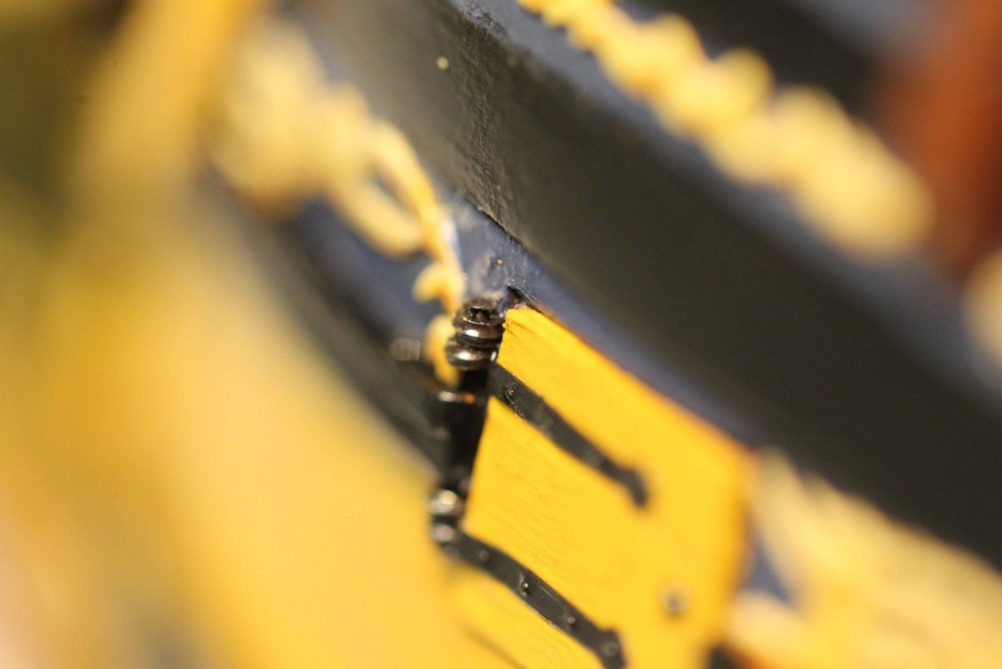
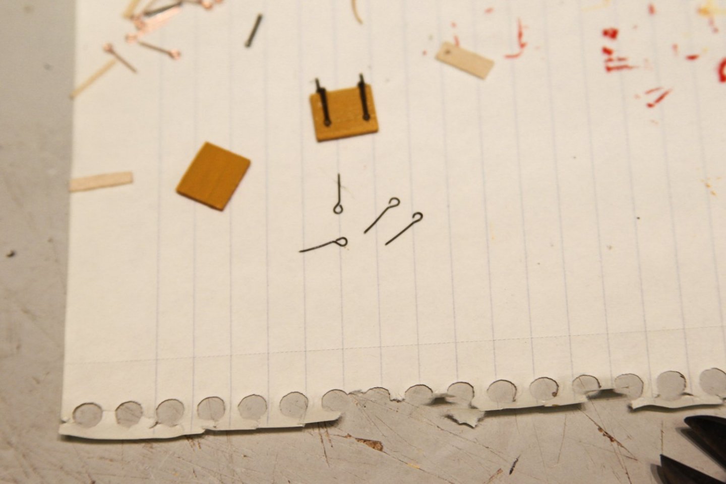
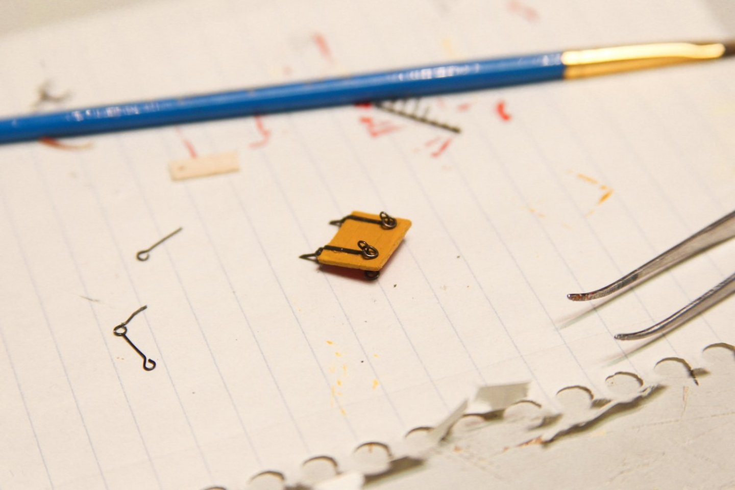
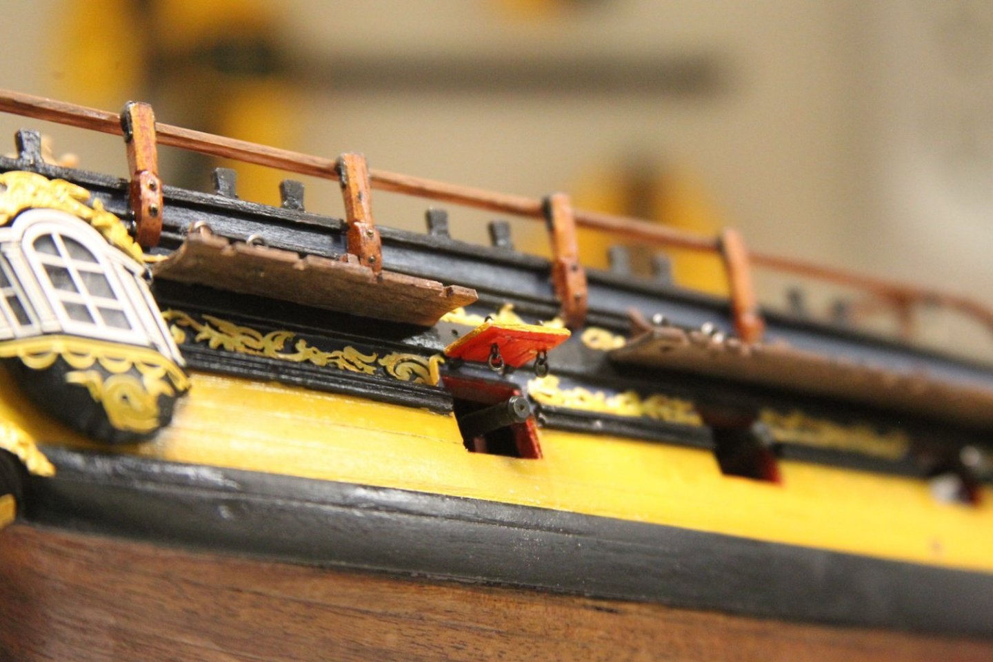
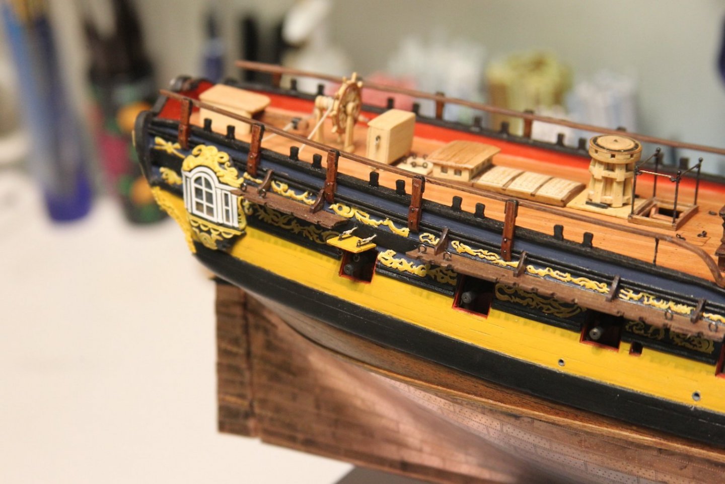
Thanks very much Starlight, Dave, Grant, and Mark - very much appreciate the look-in and comments. Moving on the the bridle and gun port doors/lids. According to most sources, the bridle port doors' primary purpose was to provide access to the anchor lines as well as other ancillary functions. As such, it was hinged horizontally rather than from the top as with gun ports. I'll note an early mistake of mine here for other builders: this port should have been shaped quite a bit differently than the gun ports when it was cut out. That is certainly illustrated in the plans - and I just missed it way back in the build. So mine is basically the same size as the gun ports which is incorrect. At any rate - it's pretty straightforward to put together with the exception of the hinges. Rather than try to cut my own, I decided to use some parts that I hadn't intended to use - the kit provided hammock cranes; as I'll be making my own later. I cut the eyelets off of these bits, and repurposed them as hinges by lining them up and inserting my smallest pin. I sharpened the ends to create pins, then inserted them into the doors and also the hull. Then I lined up the hinges on the door to appear as one solid piece. I think it's worth noting that the bridle port door has a bolt on the outside as the ring bolt is on the inside. There isn't a need to open it with a line as with the gun port door. Speaking of which - I'm only creating one gun port lid on the furthest aft gun port - the one which would have housed a cabin. I'm following Dan and the TFFM's lead here that the other gun ports were all exposed to the elements and this would've been the only door. It's up for interpretation to be sure, but it's what I chose - helped by the fact that it's also the one that is in between channels. Construction is very similar to the bridle port of course with the addition of the eyebolts and rings. I turned the eyebolts from wire, fed them through the drilled out hole, then turned them again on the other side. This was a bit tricky using jeweler's pliers and took some fiddling with tweezers once they were in, but created a more secure piece than trying to glue an eyebolt to each side. Lids were mounted the same way as the bridle port with my manufactured hinges, then the rigging was added extending through two holes drilled just above the lid.


- 323 replies
-
- 10
-
-
- Victory Models
- Pegasus
- (and 3 more)
-
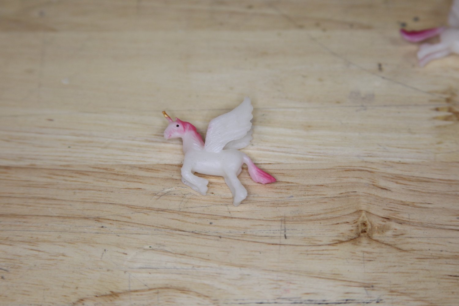
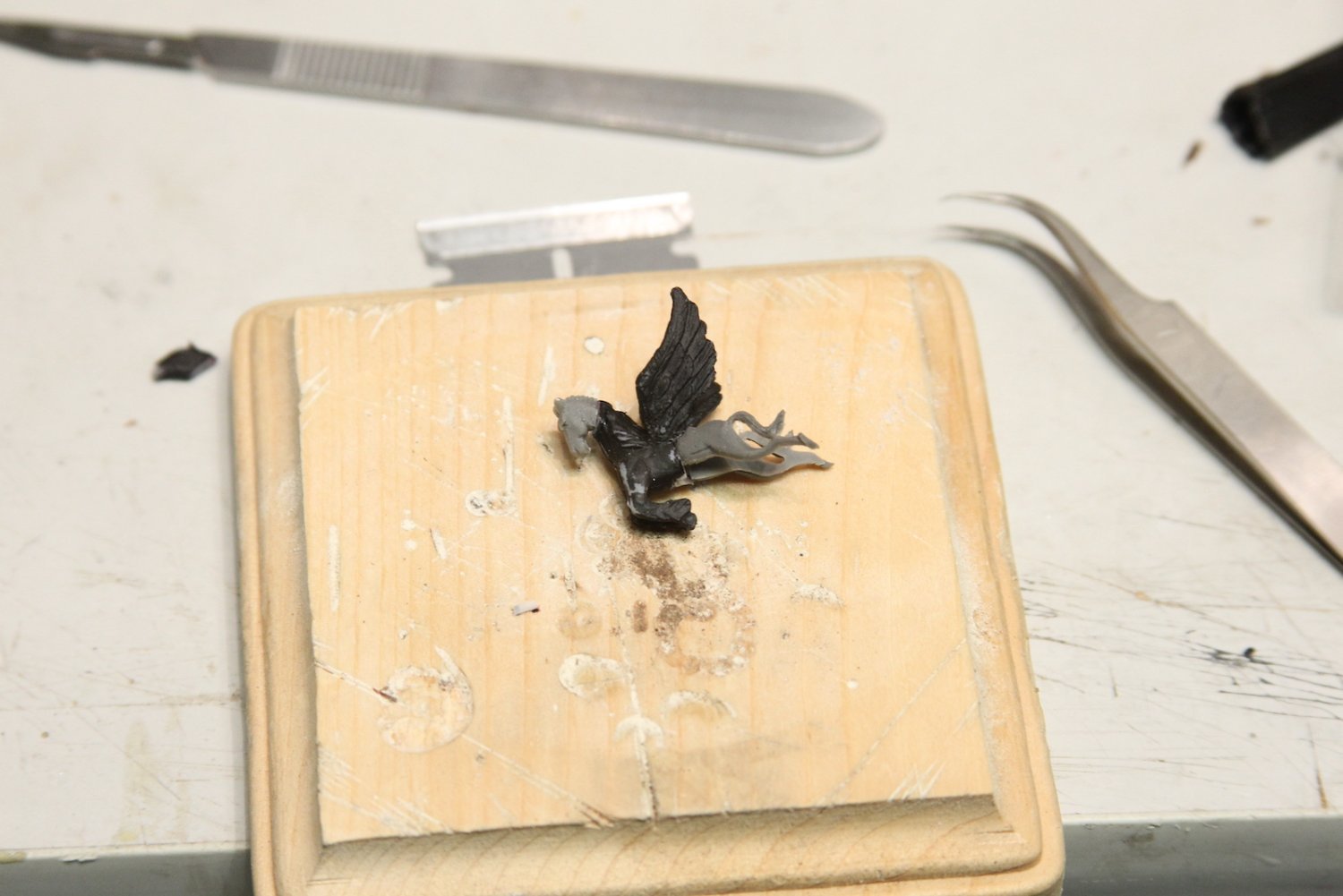
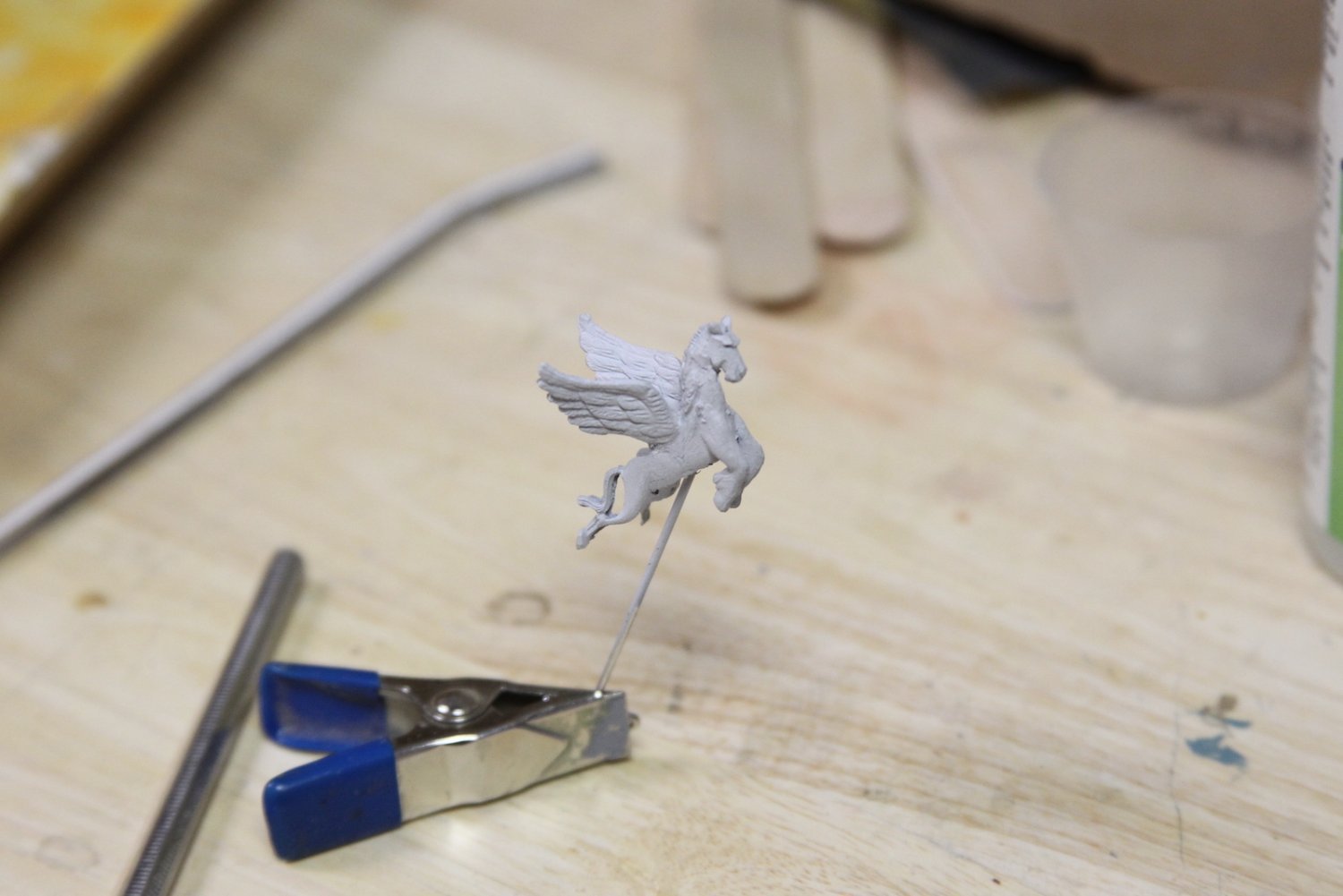
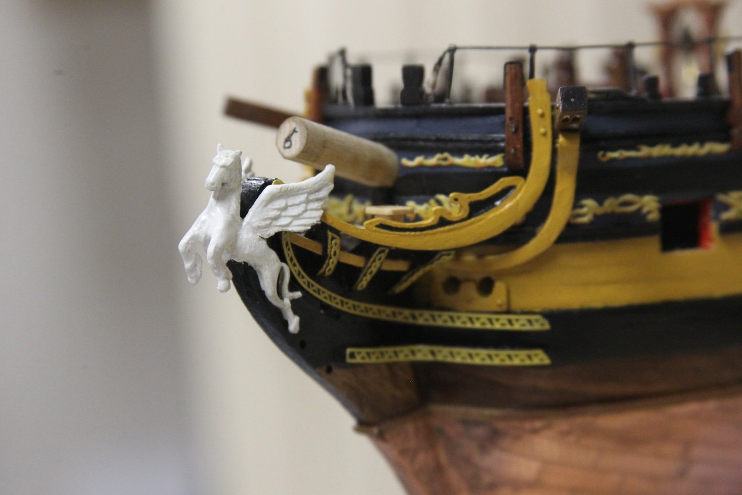
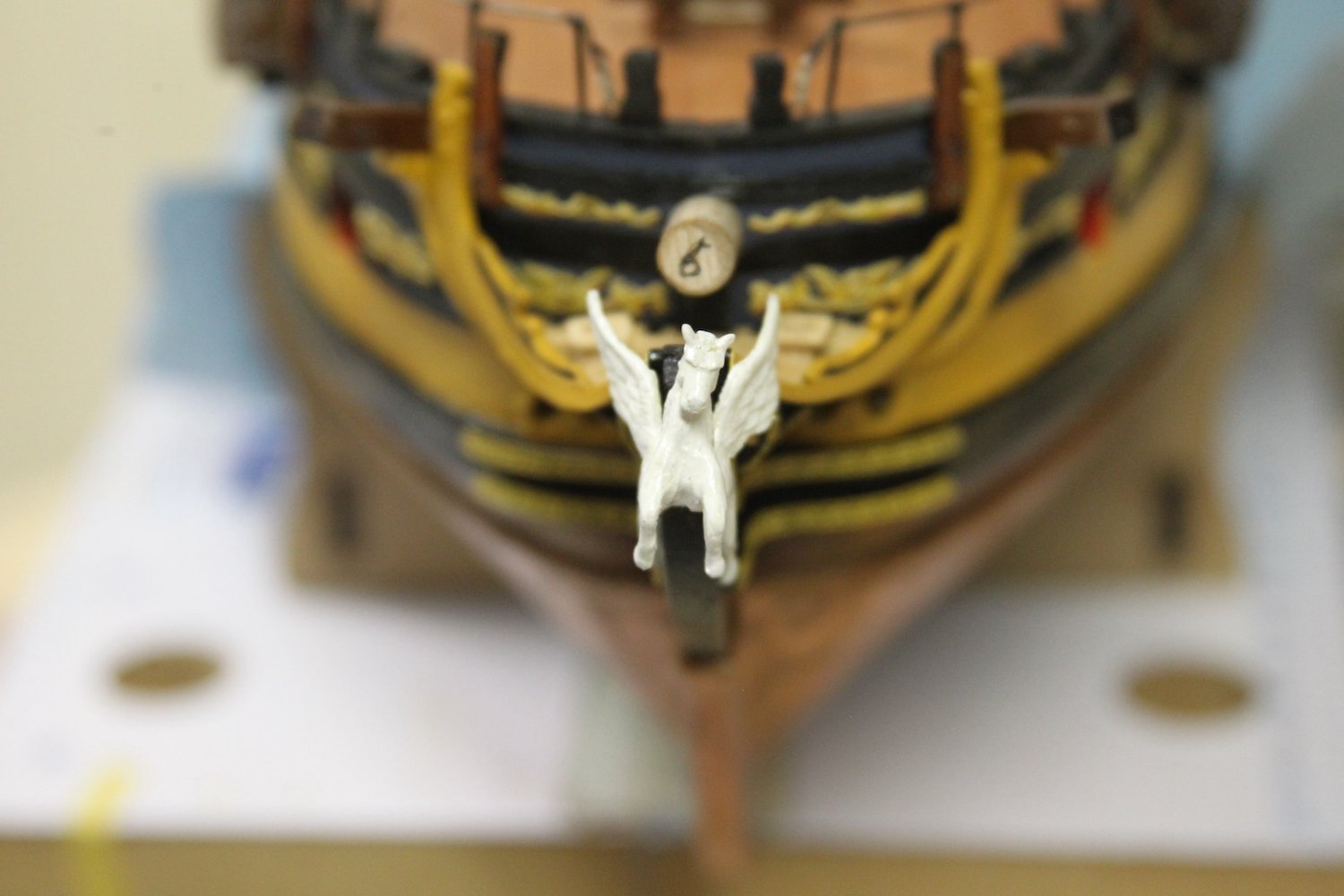
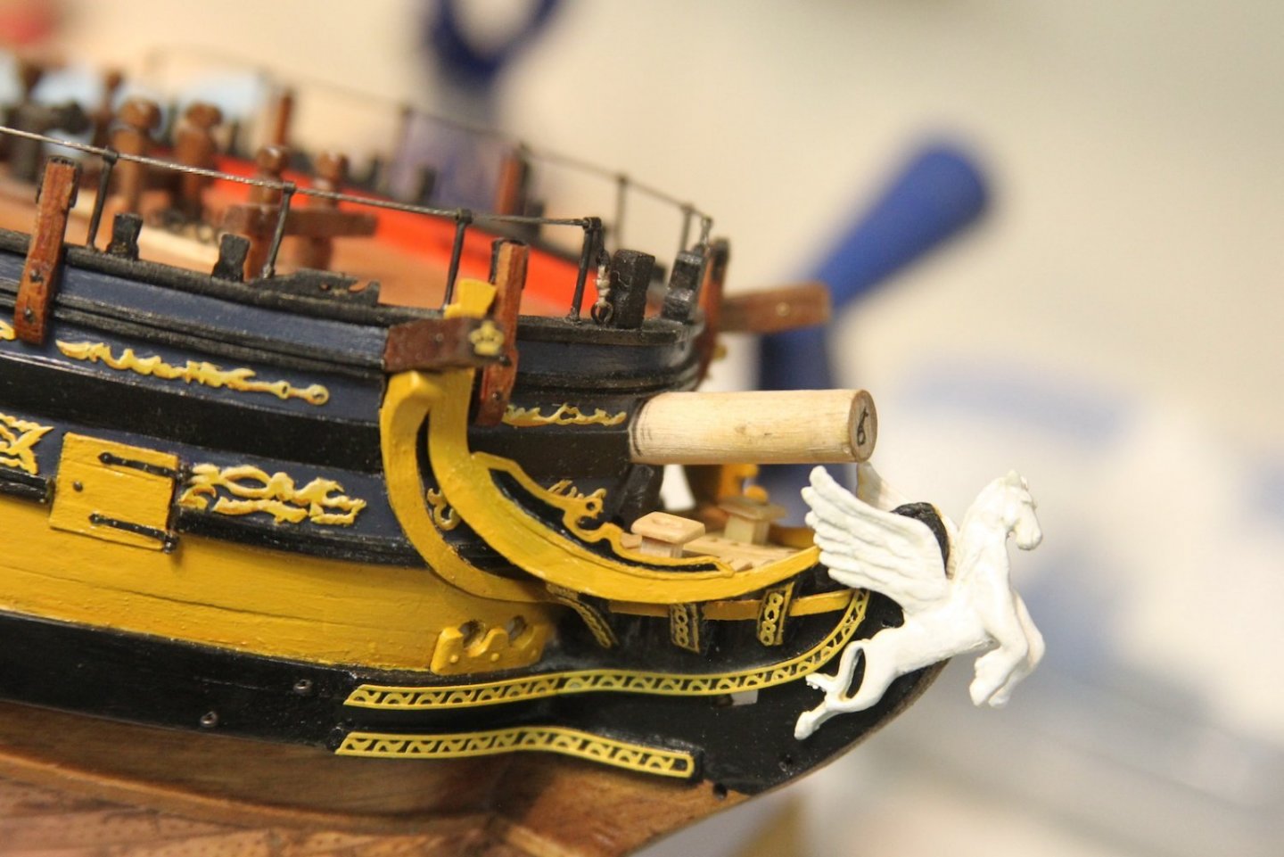
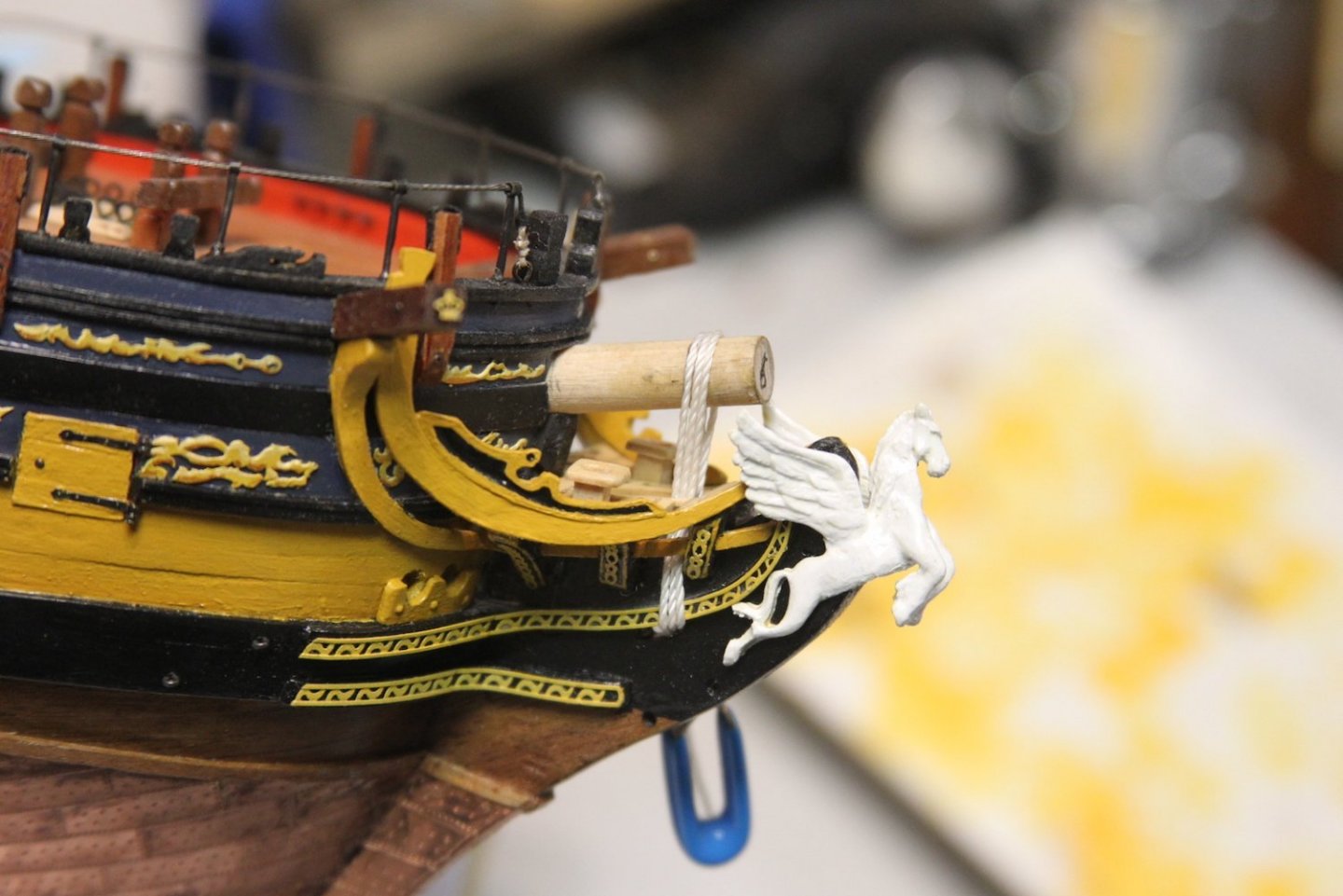
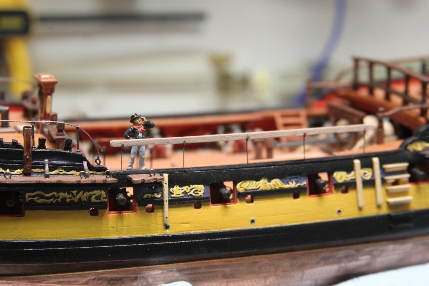
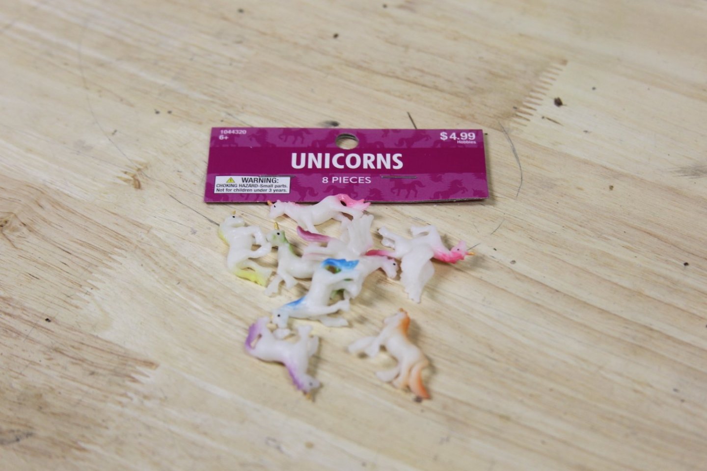
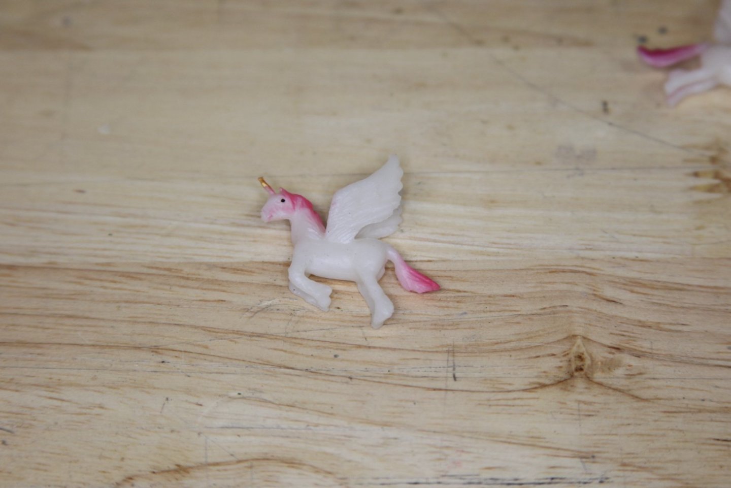
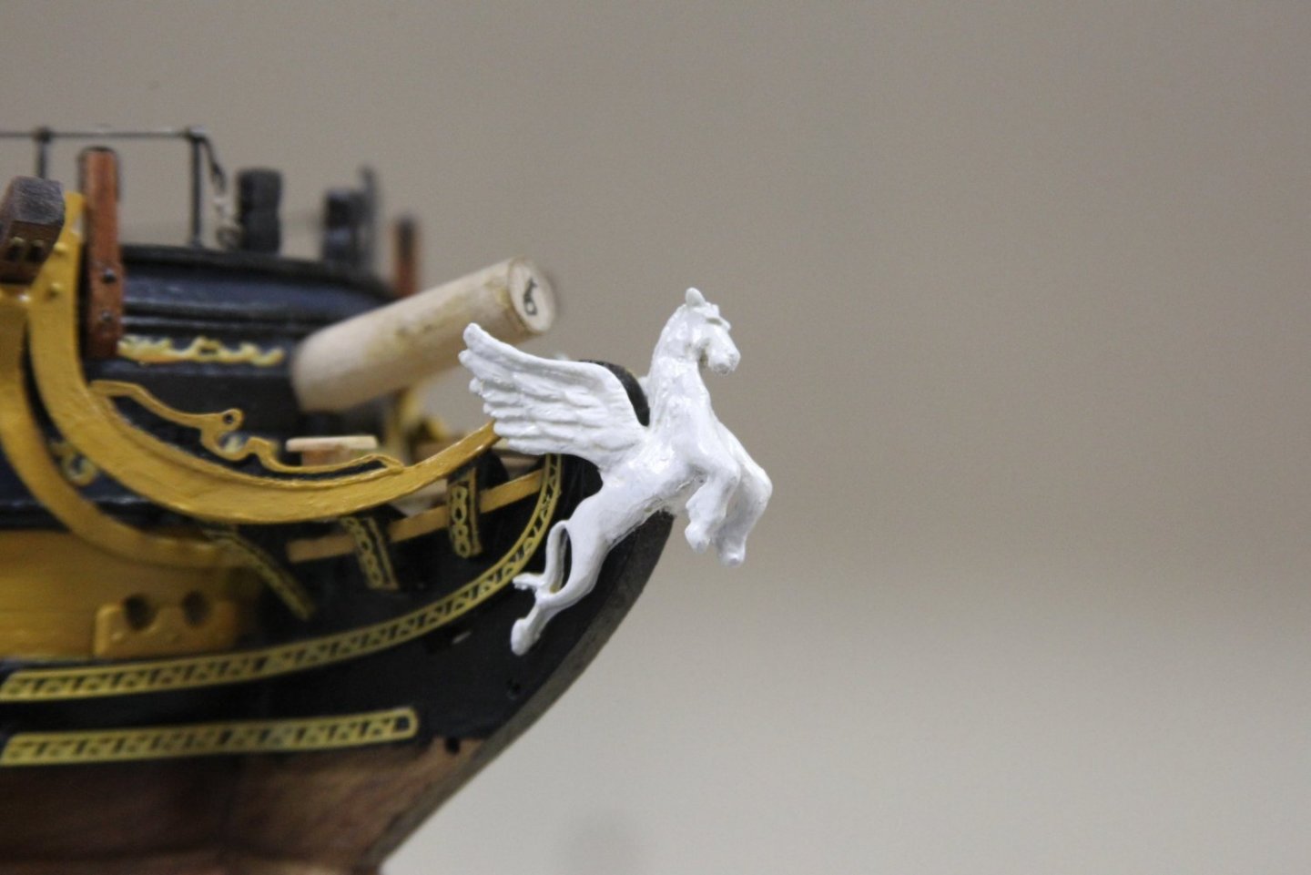
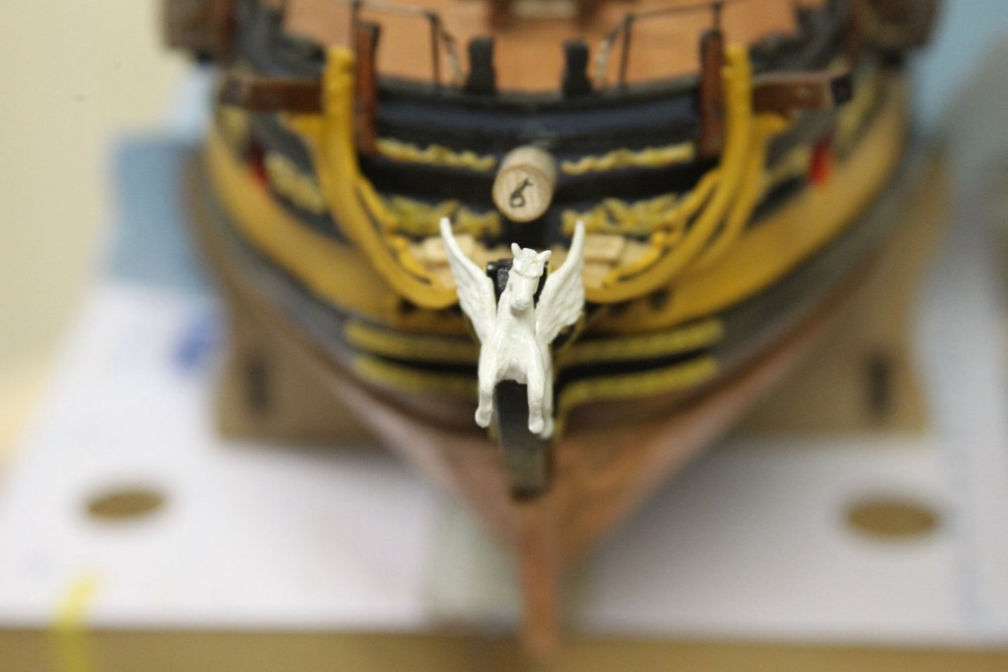
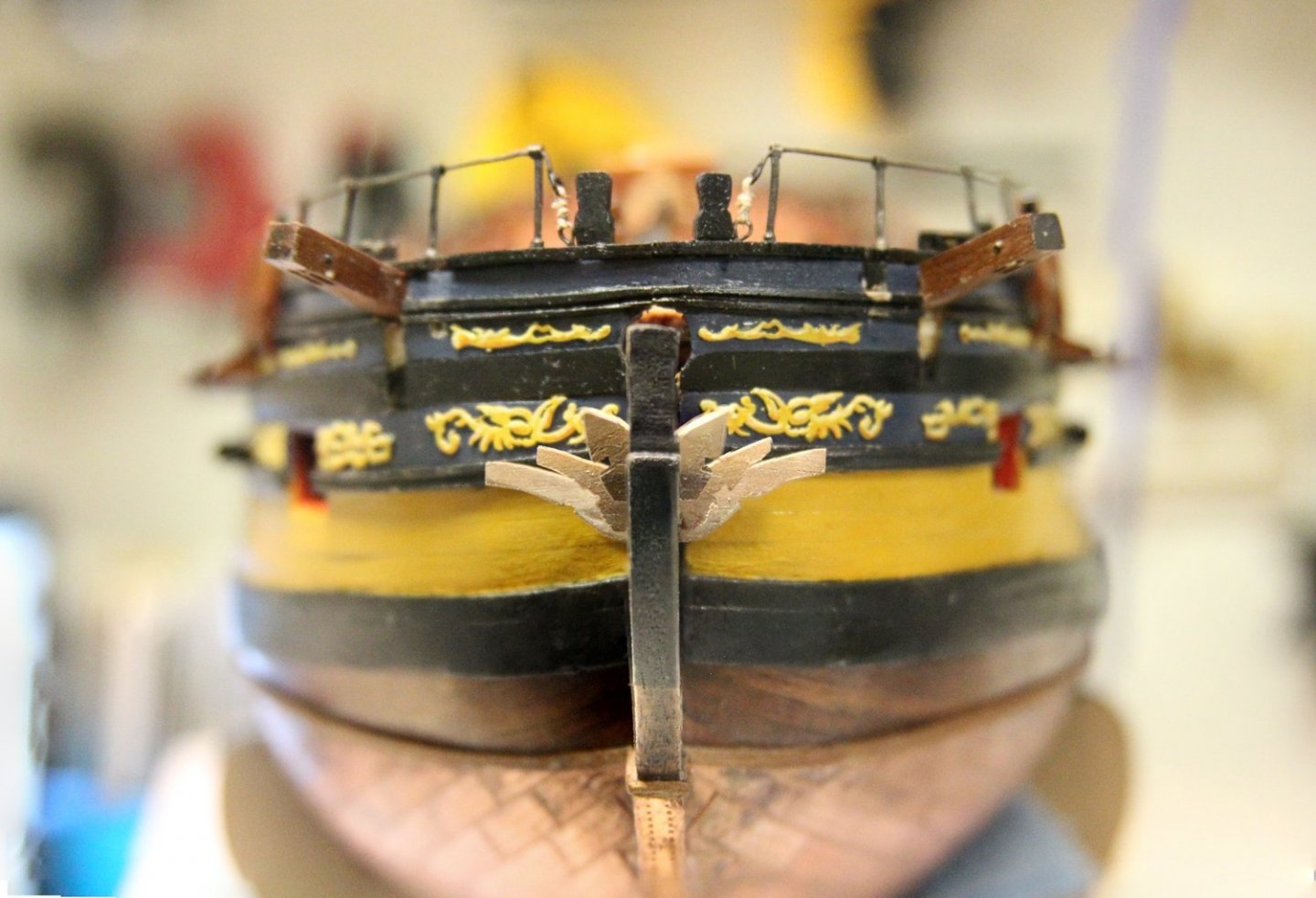
The Pegasus on the Pegasus: I've been both looking forward to this part and also a little bit nervous about it. I've had something specific in mind for the figure head since I first opened the Peg kit. While the kit figure is fine, I really wanted mine to be unique to any one else's. While I absolutely LOVE @Trussben's carved figure head, I wasn't sure I could get that pulled off in a 1/64 scale, and I WAS sure that I would not be able to pull off justifying the cost to the Admiral. 😜 I'd been searching for other solutions for weeks when I finally stumbled across this package of little toys that were perfect for scale. I really dug the wings and the body, but the head left much to be desired obviously. Also - there was no way the rear legs would work. Since it's a little rubber toy - I wasn't going to be able to manipulate it much and I was concerned about painting, etc. So... I ended up creating "Franken-Peg" - a combination of the kit figurehead and the one I'd purchased. The rubber was really receptive to cutting and gluing it together - and looked even better after a coat of primer. Some final adjustments needed to be made after it was mounted, but I'm pretty stoked with the end look. I've seen some good looking wood color paint expressions, but I wanted to stick with the traditional white figurehead look common to the Royal Navy. So "Franken-Peg" has several coats of paint to give her a carved look and some depth - which was important to me. And it's definitely not a figurehead that will be seen on any other ship.


- 323 replies
-
- 17
-
-
-
- Victory Models
- Pegasus
- (and 3 more)
-
Nice work thus far @starlight. It's always a little bit of interpretation when you see photos rather than in person, but I agree that color looks a bit off. Lots of folks here have come up with some good combinations which all seem to depend on brand. Personally, I leaned toward artist acrylics and a combination using a vermillion red. But I still don't think mine is quite as close as others to standard Royal Navy colors.
- 82 replies
-
- 2
-
-
- Fly
- Victory Models
- (and 2 more)
-
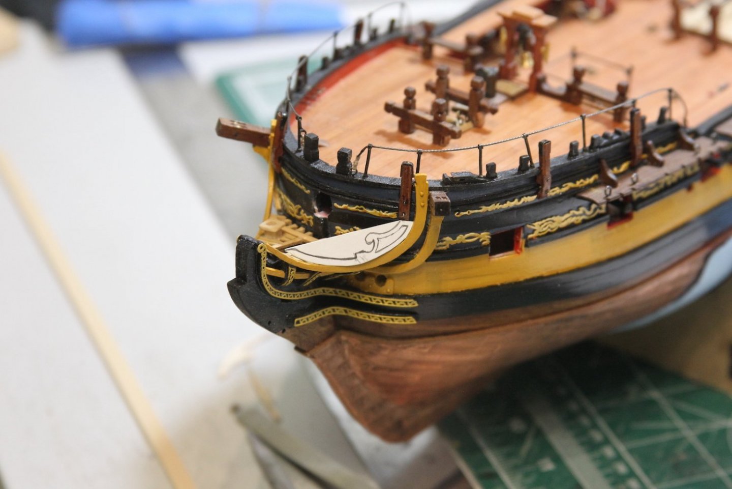
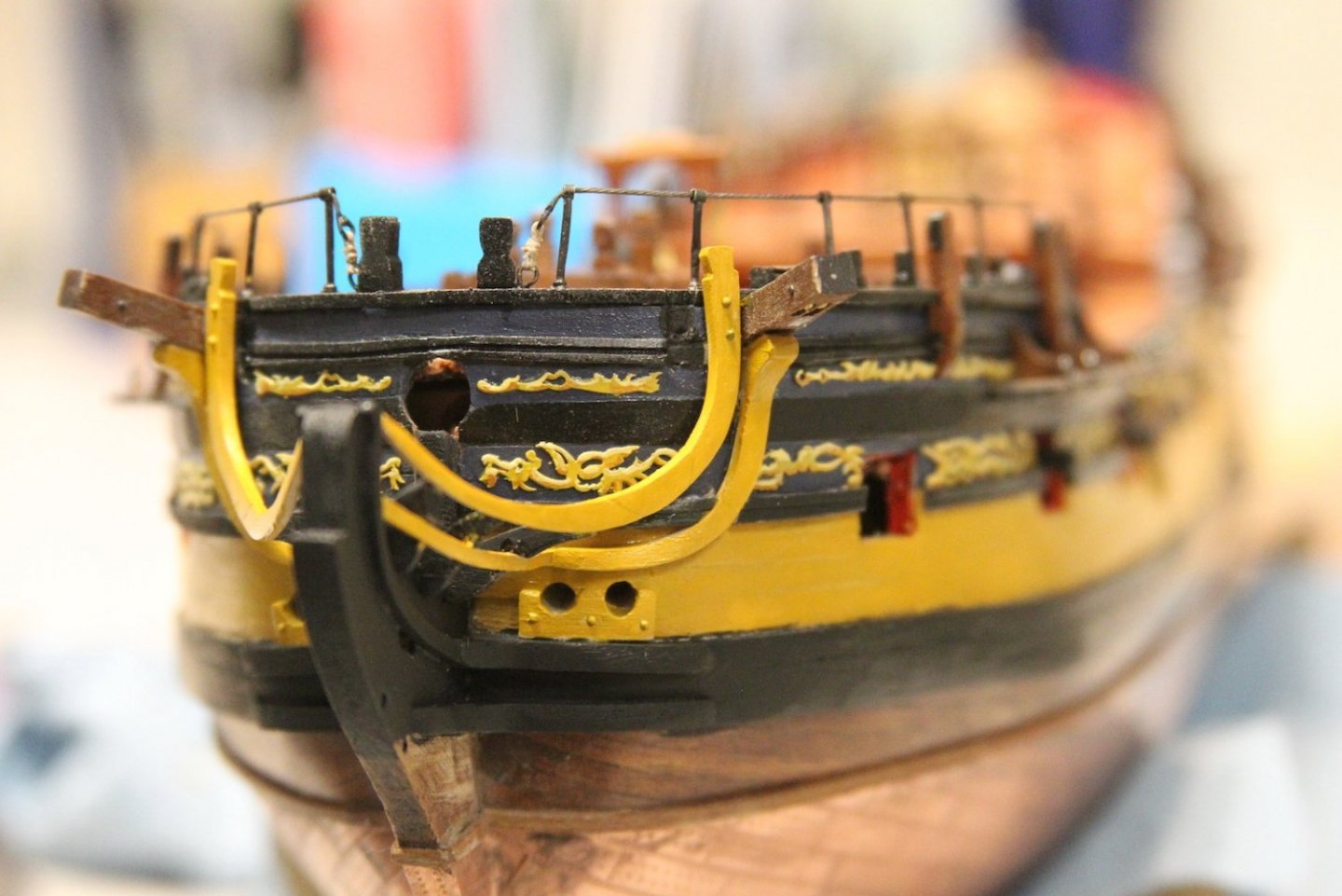
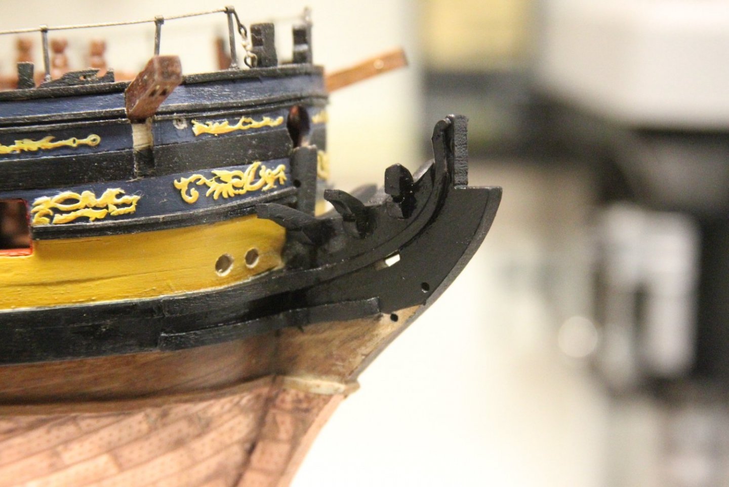
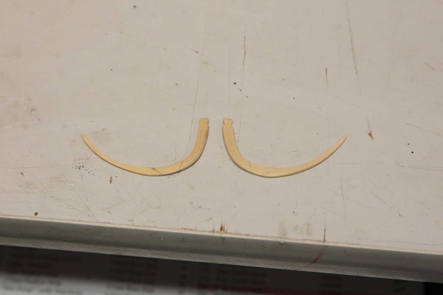
Thanks BE and Starlight - all that went a little better than I anticipated. I was a little bit disappointed that the kit didn't provide the false rails, as I thought it might've been an easy add to the laser cut sheet. I also realize that is a selfish perspective - mostly because of my sketchy carving 'skills'. None-the-less, I wanted false rails, so I started with a card stock drawing fitted to the head rails, then carved them out of boxwood. Knowing my scratch build main rails would not be identical, I cut the false rails with a little extra room on the bottom end so they could be fitted neatly to the specific curvature of each main rail. The inner relief was carved out using my smallest Dremel engraving attachment then smoothed out using a pointed burr. The rails were then mounted and painted. A small amount of filler was used in the areas that didn't match up perfectly.


- 323 replies
-
- 11
-
-
-
- Victory Models
- Pegasus
- (and 3 more)
-
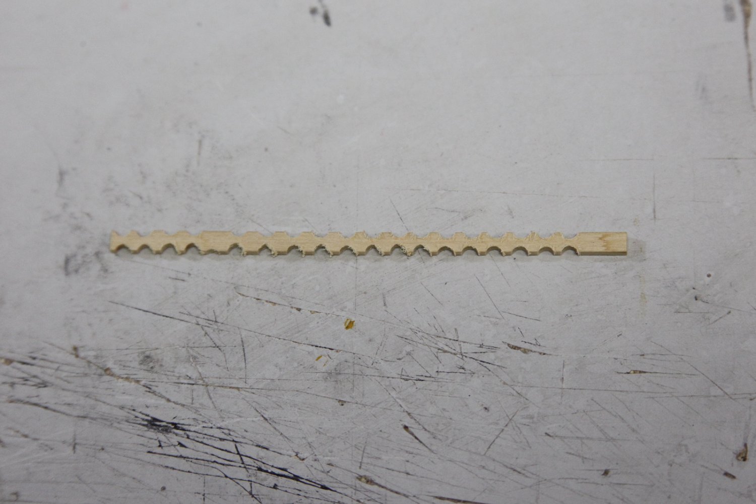
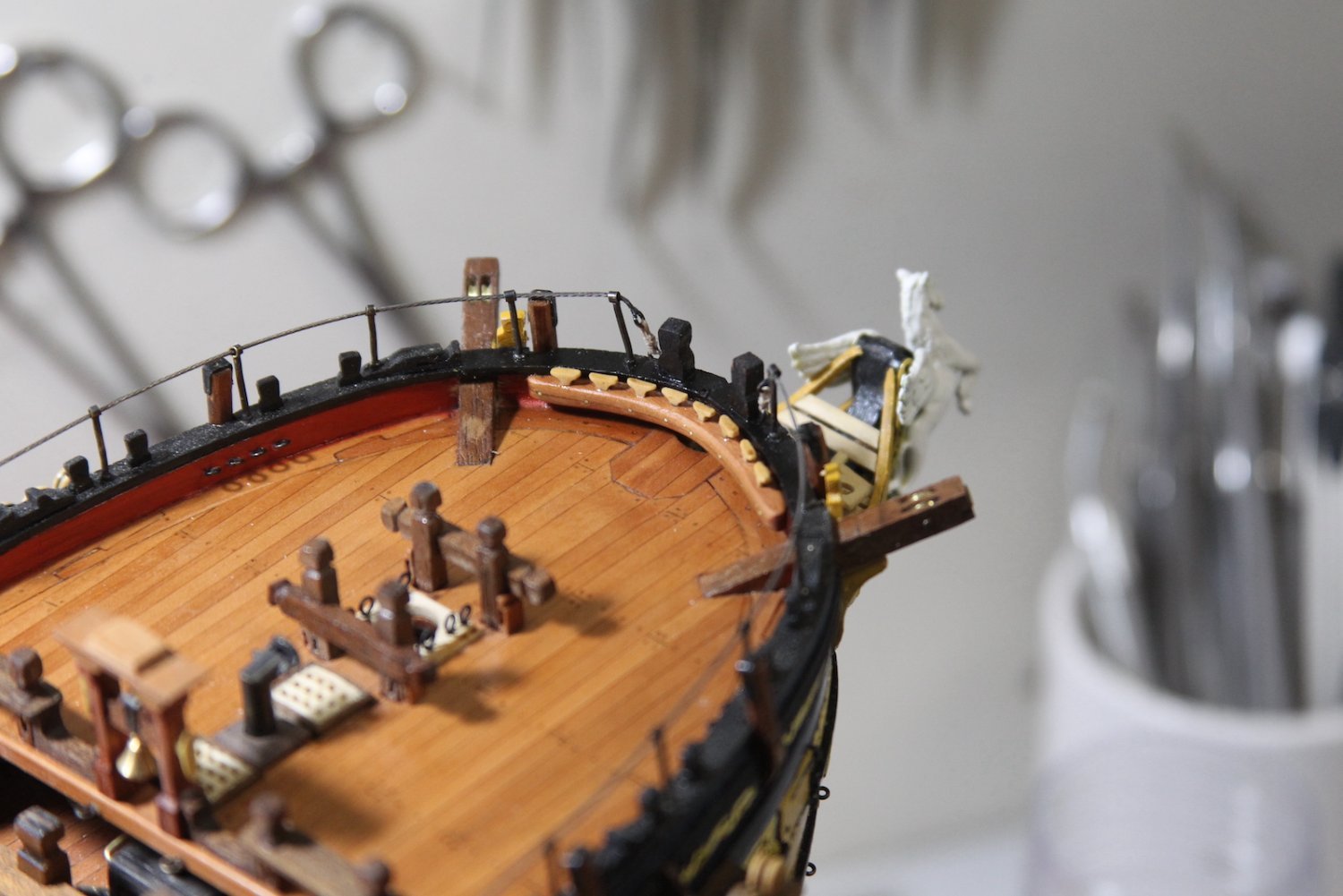
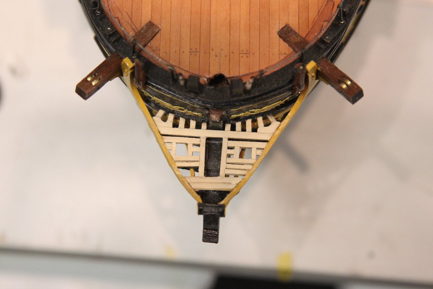
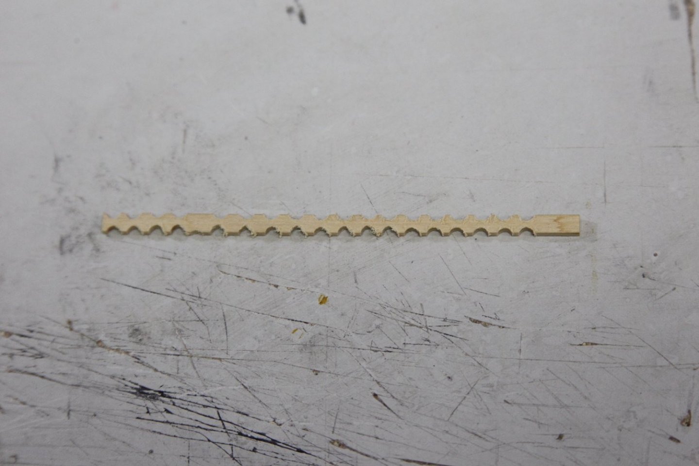
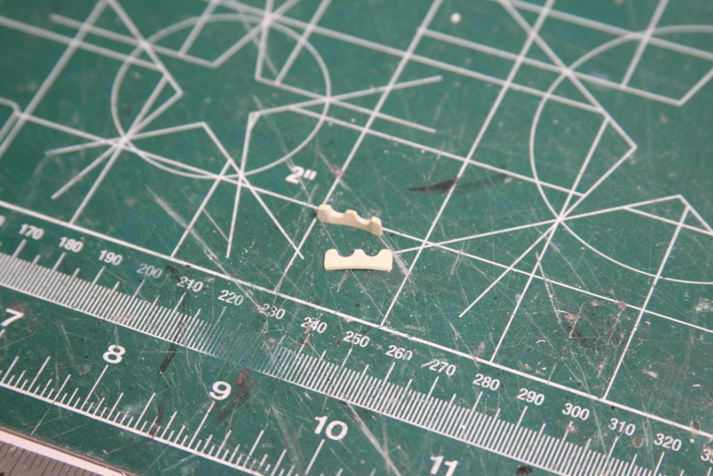
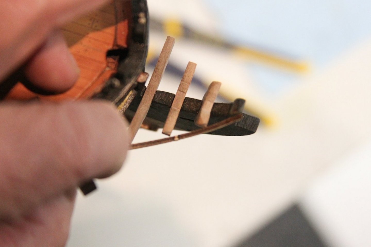
Thanks Bob, much appreciated. Any kind of carving of shapes isn't really my forte, so this is definitely part of the build where I'm really never sure how it's going. This is one of those short but long posts - meaning the post isn't very long, but it took me the whole day (and blowing off much of work) to get done. I tried to model the grating after the TFFM style, and first attempted to cut grooves in which the grating could fit. But that did not work at all - I couldn't get them precise enough even using boxwood. So once again I had to make some concessions due to the small scale. I had to cut, measure and place each piece individually because my scratch made rails and timber heads were fractionally different. I started at the base of the bow, added the most forward supports, then filled in the grates in between. The process was basically to cut it close, test fit, sand the edge literally three or four strokes at a time, then test fit again until it slid into place. In the picture there's one piece of grating missing on the starboard side. That's because I thought I glued it in place but didn't then when I shifted the model to take the picture it fell out and I didn't notice until I saw the photo. 😛 Finally the seats of ease were added. Nothing particularly special about them. I sized them to be equal to one another and then shaved off little bits of the grating to get them to fit so they'd stay mirror images of one another.

- 323 replies
-
- 9
-
-
- Victory Models
- Pegasus
- (and 3 more)
-
How clever! Is this a new thing BE? I don't remember you mentioning this before in your other builds - but it could be something I've missed.
- 858 replies
-
- 2
-
-
-
- Sphinx
- Vanguard Models
- (and 1 more)
-
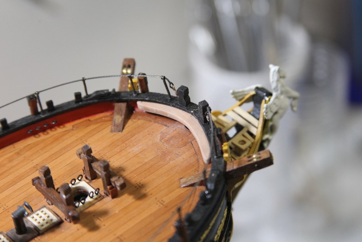
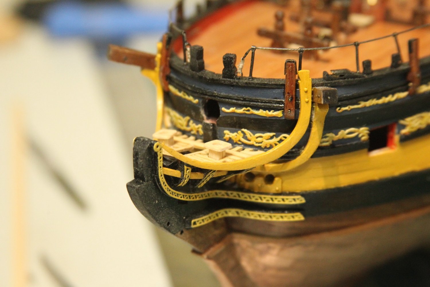
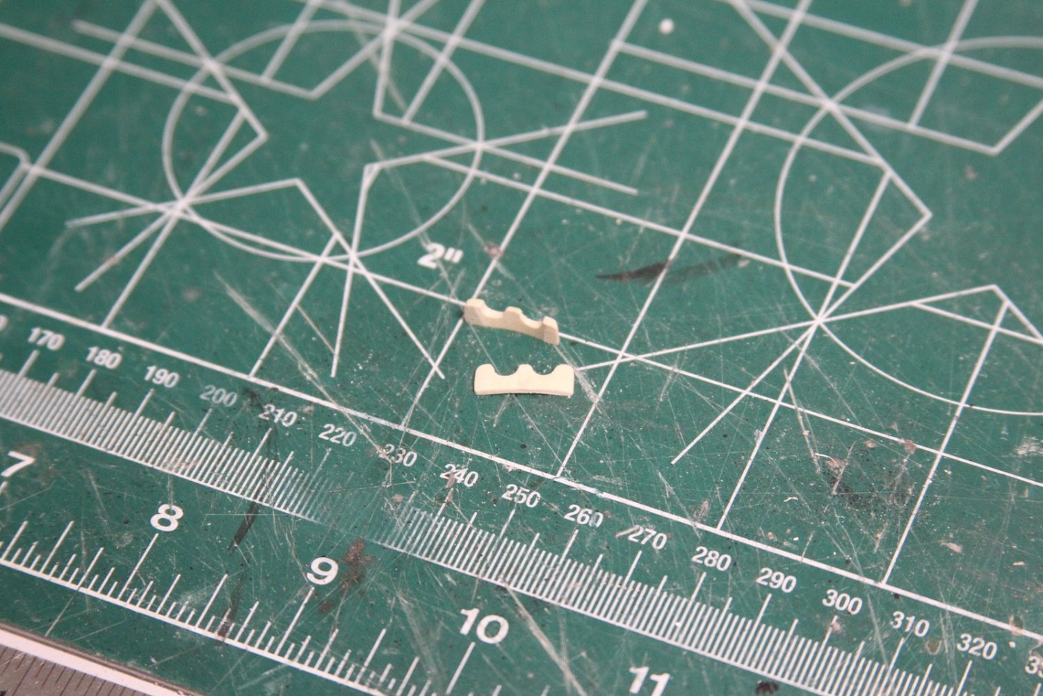
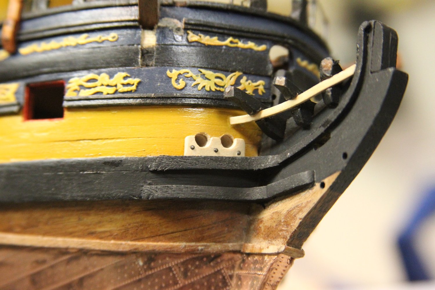
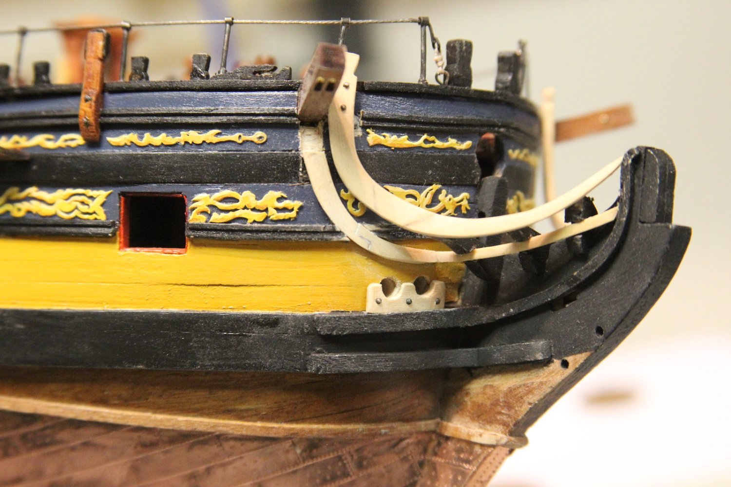
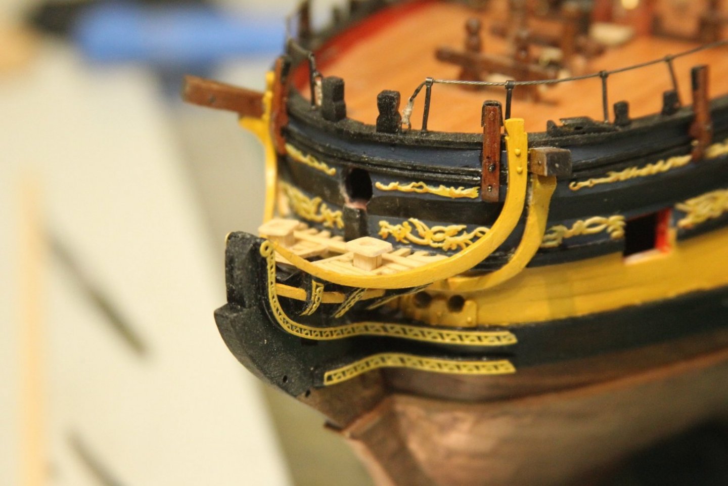
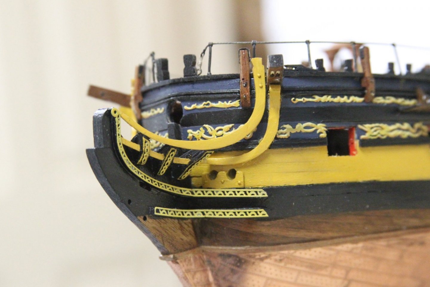
Continuing on the bow and the head works. I quickly added a little filler for the upcoming Pegasus herself; I've been working on something quite different for the figure head and I'm admittedly excited to see how she'll turn out. The filler is just an easy piece of walnut added now so I can paint it along with the rest of the bits. Then I carved out the lower railing and fit it to the head timbers - once again from boxwood. This is all very touch and go and one piece at a time since I'm basically finagling my own scratch pieces here. I cut and fit the bolsters so I could finish sizing out where the lower rail would end up. I'm electing to just have the bottom bolster and not fit a 'top half' to the lower rail where it extends below the cat head support. I've learned quickly that I need to make a handful of concessions in this area as working at 1/64 sometimes becomes just too small for me to produce the quality product for which I'm aiming. Lower rails are carved out with a curve in a similar manner as the main rails and measured out. The cathead support is carved, shaped, and fit also from boxwood. I then painted everything with my color scheme - I'm going with a look similar to the Victory stylings. I went ahead and gave this fitting a coat of paint and wipe on poly before I progressed to the covering boards on the outer edges of the head timbers. I know that's going to be some VERY delicate painting, etc, and I was hoping the coat of poly would help me fix mistakes that occur as a result of my hands not being nearly as steady as they "good ol' days". A lesson I learned trying to paint Cap'n Amati and his crew. Covering boards are cut from my thinest stock and soaked before they're shaped along the head timbers. I did have to sand down the areas where the lower rail meets the head timbers to provide the necessary fitment. After they were dried and glued in place, I added a little bit of filler where needed and painted. I heavily debated whether to added the little vertical strips of decoration along the covering boards or to just keep the yellow outline as seen on the Victory and other ships. After a lot of holding it in place and debating, I finally decided that the added decoration somewhat detracts from my sketchy paint job. I REALLY had a hard time with those little yellow lines after trying to mask them off and everything else. I even tried using tiny strips of yellow tape but the color didn't match the other ochre. I ultimately got the best results I could by just painting them free hand. The added vertical decorations also blend with the cheeks, so I'm cool with it. On to the grating...


- 323 replies
-
- 14
-
-
- Victory Models
- Pegasus
- (and 3 more)
-
Very tedious work - but really, really pays off. Very nice BE.
- 858 replies
-
- 2
-
-
-
- Sphinx
- Vanguard Models
- (and 1 more)
-
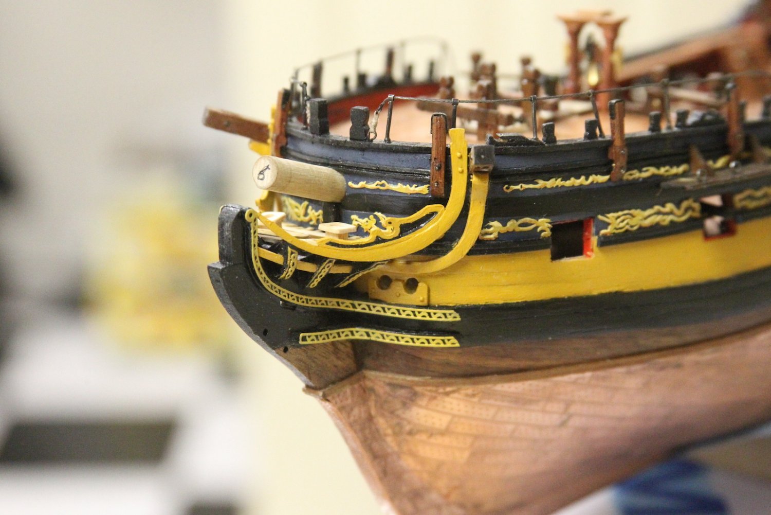
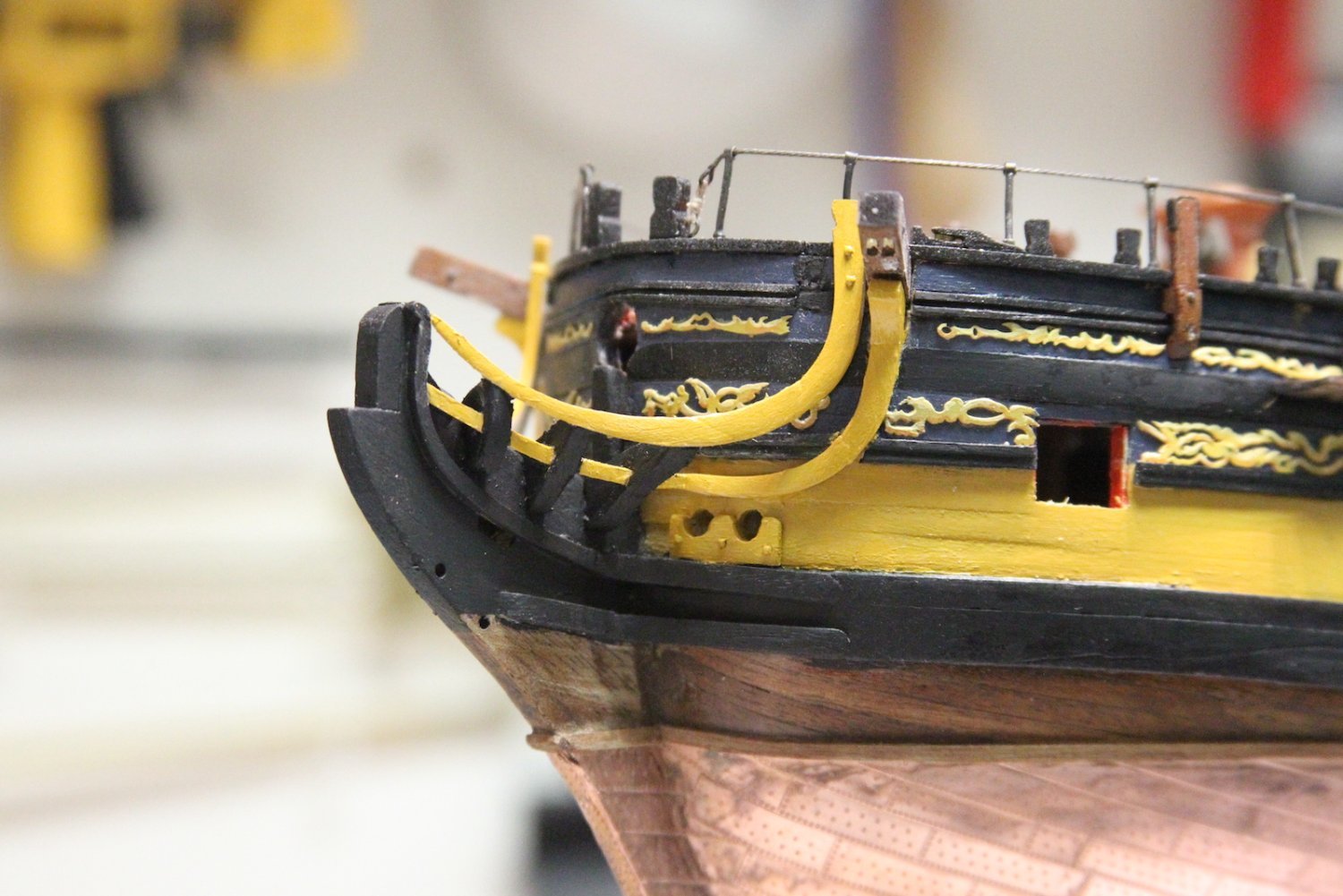
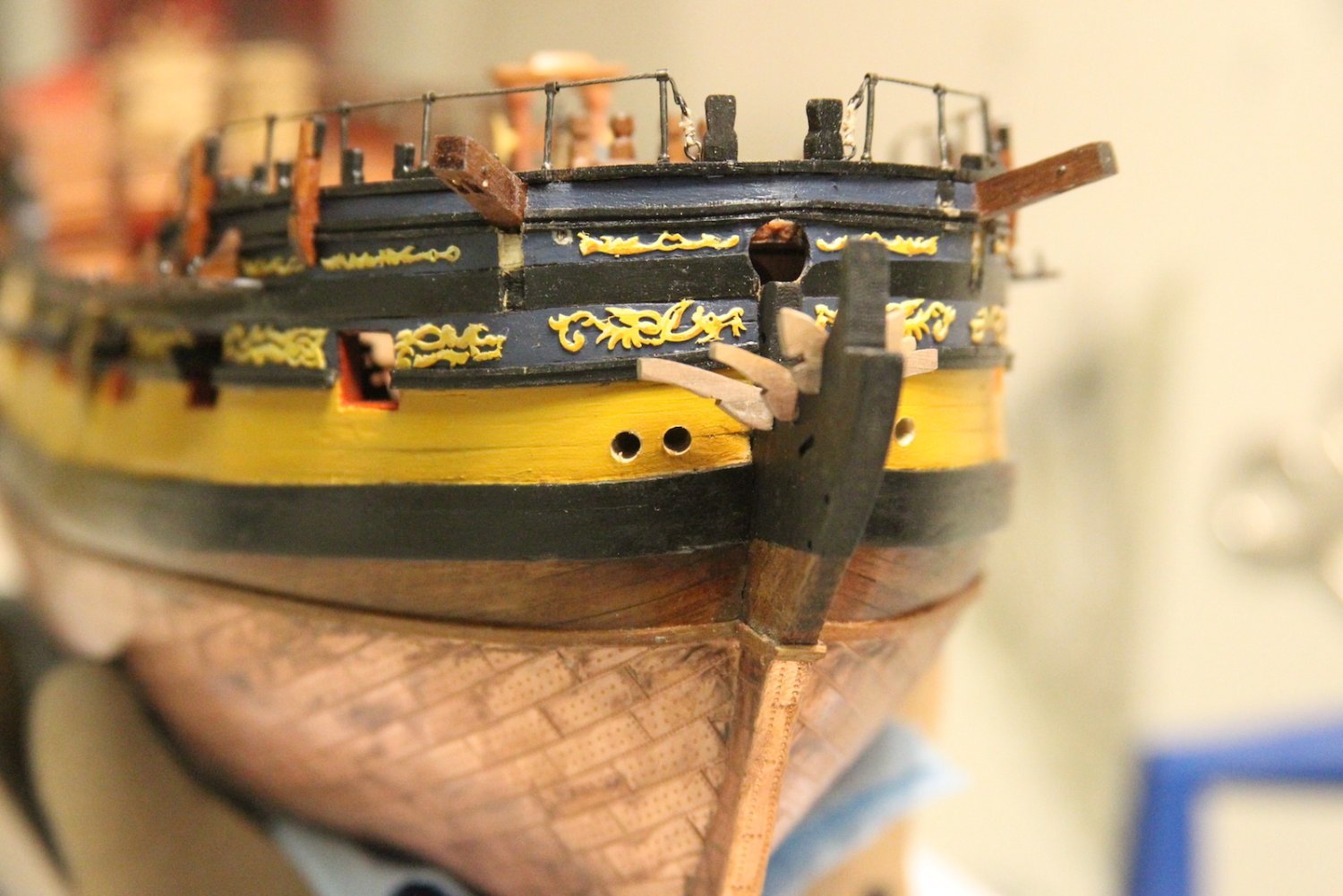
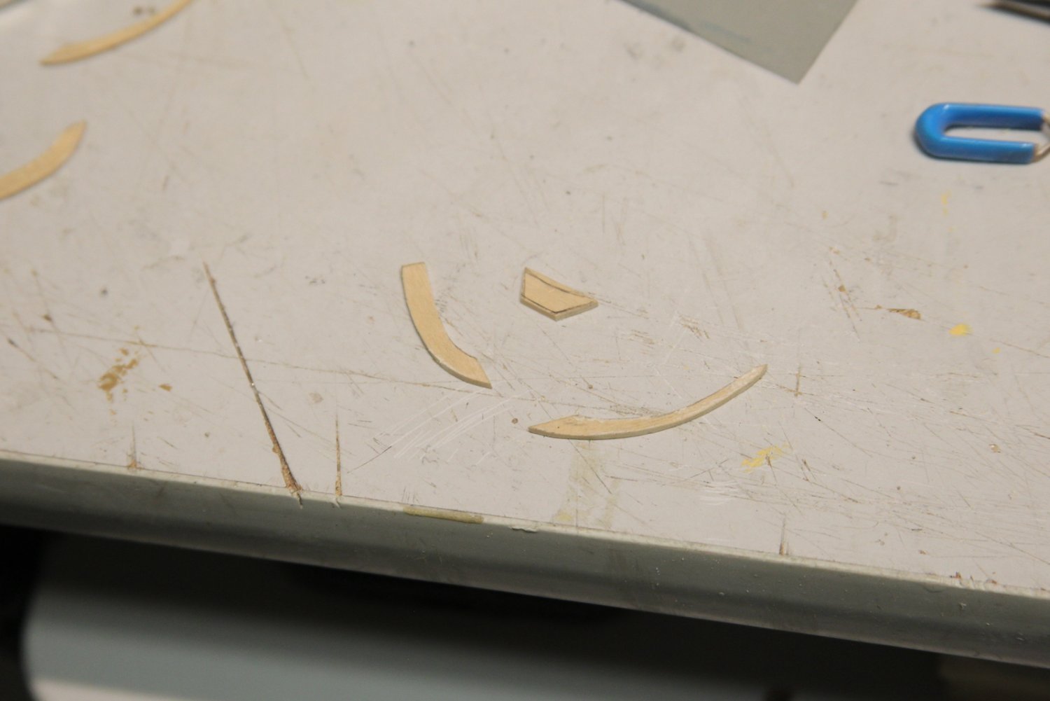
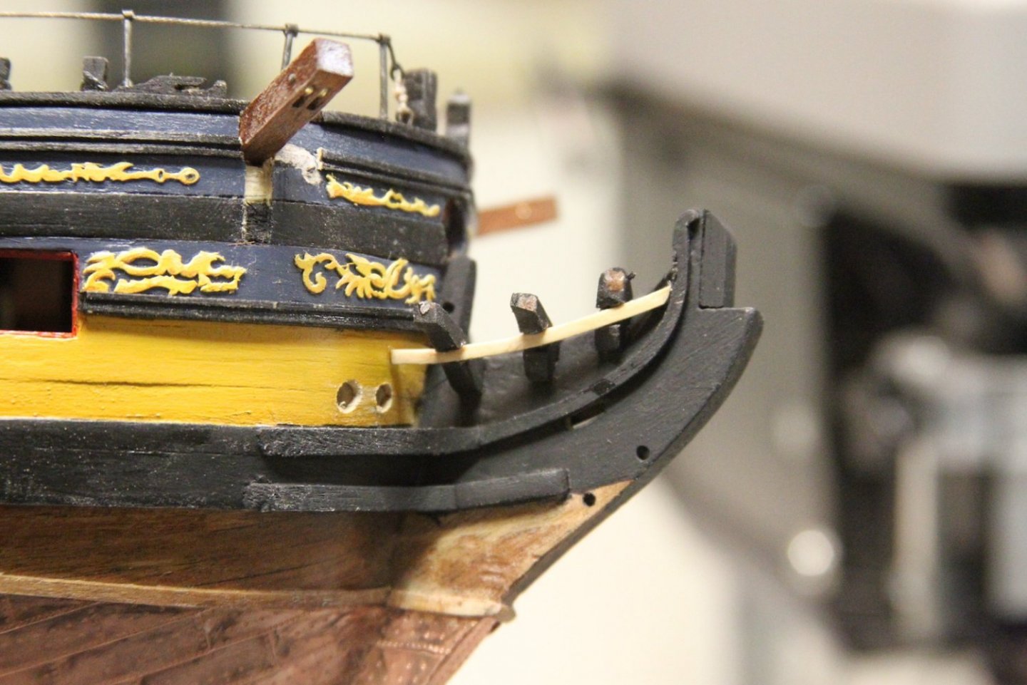
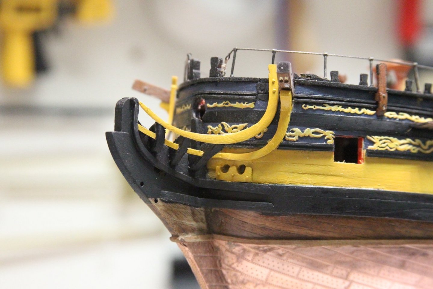
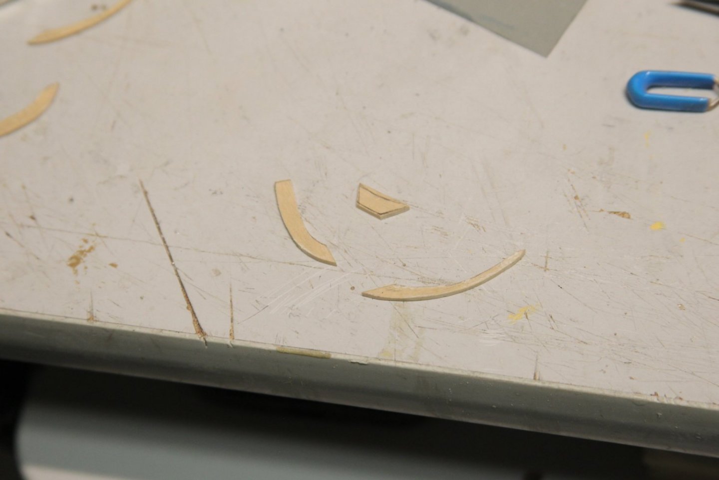
Continuing with the headworks, next up was the simple, yet always anxiety inducing job of cutting out the hawse holes. I marked them out and then used a very high speed drill bit to avoid flaking or other damage. I was able to reshape and use the precut pieces for the cheeks. However, I did run into a slight issue. Once again, because of the way I mounted the main wales, the cheeks now conflicted with the gammoning slots when I extended the hair bracket from the upper cheek. Not a huge issue, I just drilled out more room for the gammoning and added the hair bracket moulding. The main rails were quite tricky of course - as they are for everyone. I chose to cut them from boxwood in three separate pieces. I used a template to measure out the necessary distance, then temporarily mounted the two end pieces. This allowed me to fill in and custom fit the middle piece into the gap. Once it was all fit, I glued it together and and sanded it down. It's worth nothing that there is also a slight angle between the three pieces allowing it to guide along the bow properly. I need to measure out and cut a few more pieces before I start permanently assembling it all. More to come of course...


- 323 replies
-
- 11
-
-
- Victory Models
- Pegasus
- (and 3 more)
-
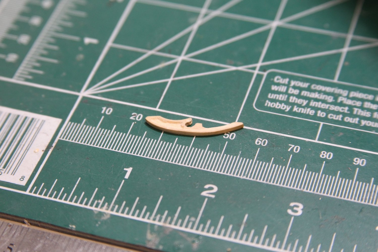
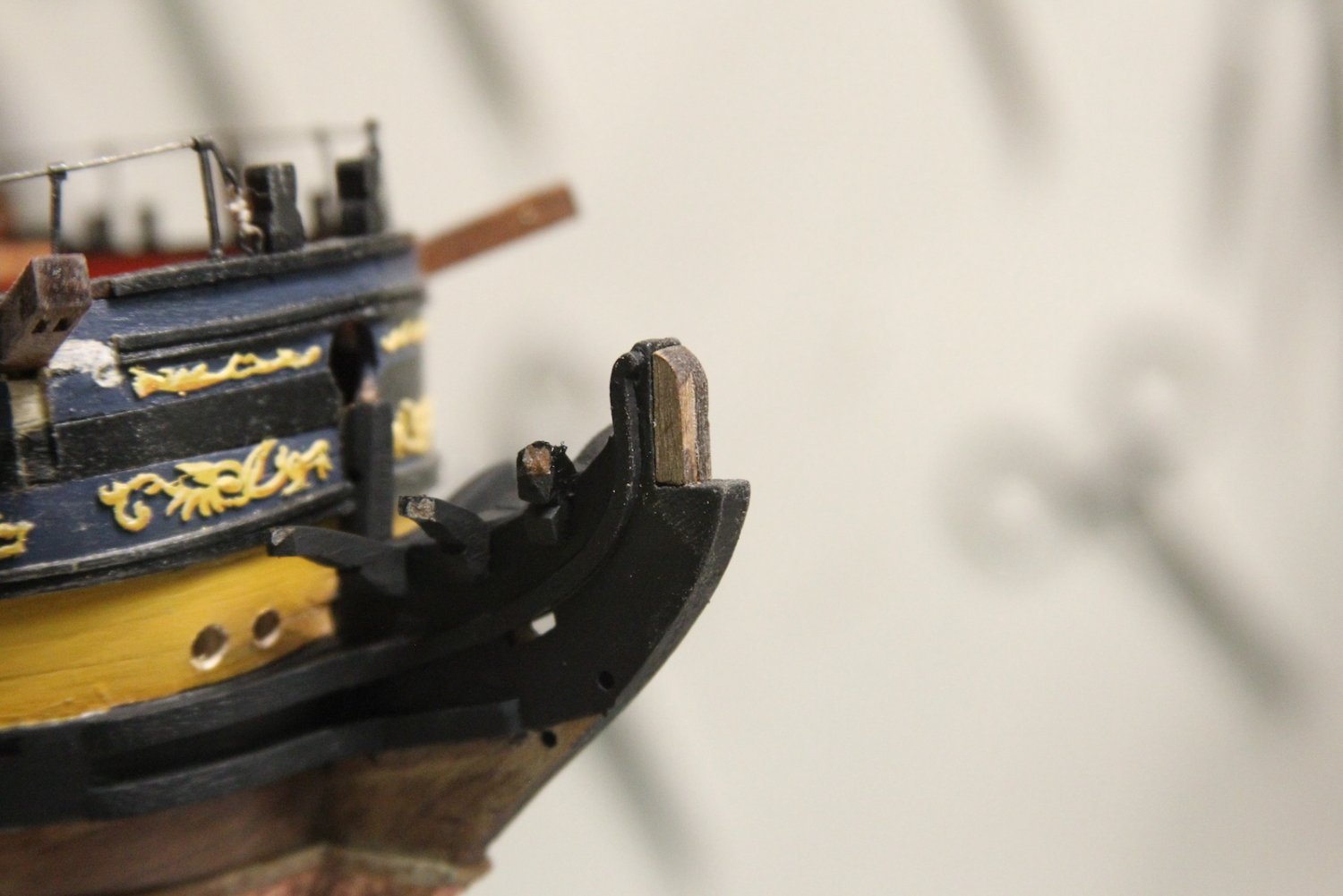
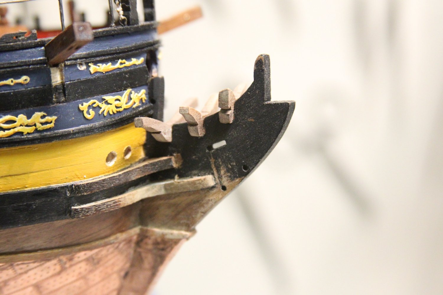
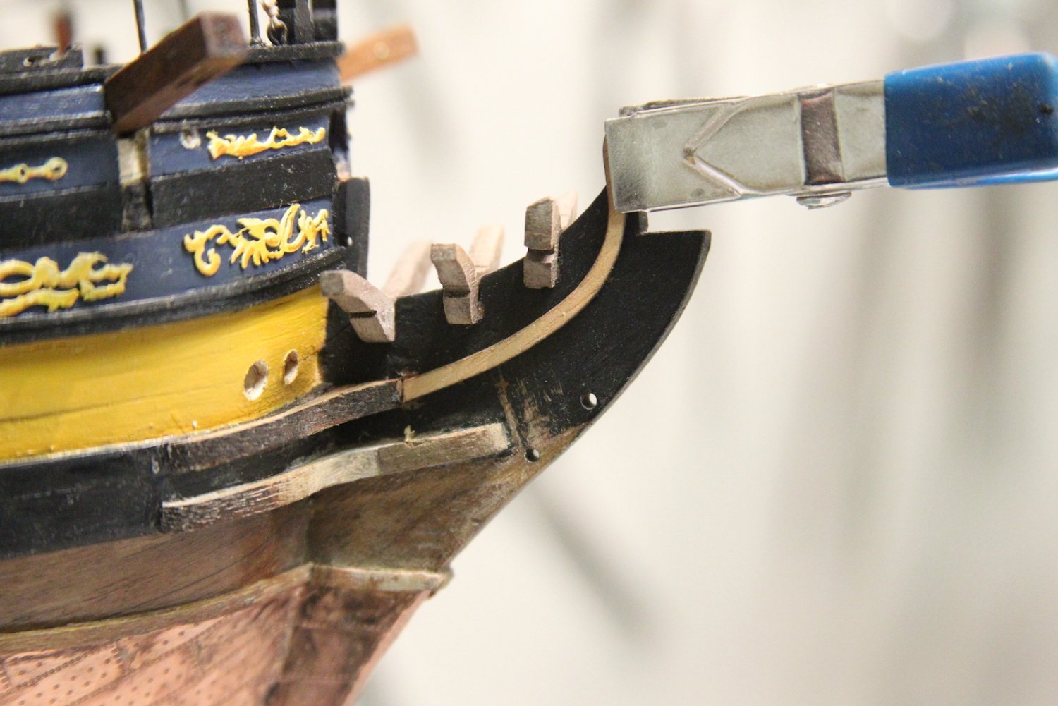
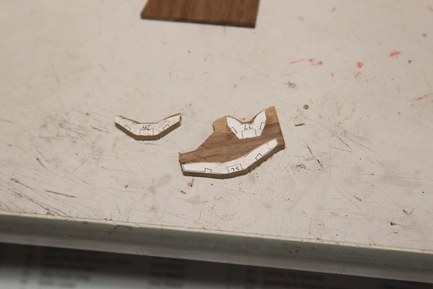
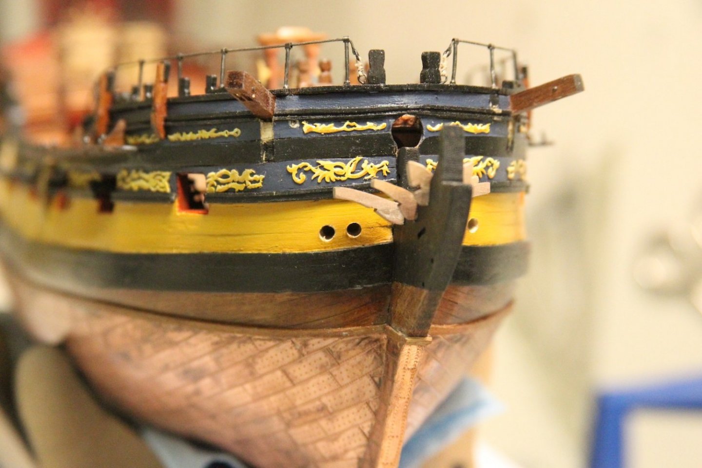
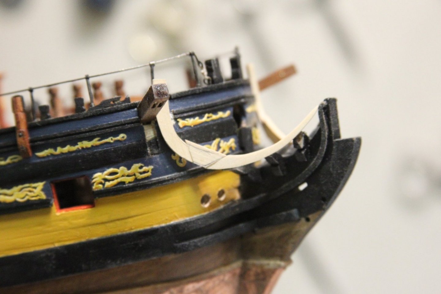
A keen observer to this log may have noticed over the last couple of months that I've done a lot around the bow of the ship but have not addressed the head works. That's because the head works scares the crap out of me. One of the most delicate areas of the ship to put together, but also the most visible. Yikes. That said - it's now where I'm at and there can be no more avoiding. I've noodled through what I'd like to do here, and it'll be a based in the plans to start, but then I'll fill in the grating, seats of ease, and other elements not included in the Peg plans. Also, I'm still finalizing what gets painted and what doesn't; so when I combine that with the delicacy and added elements, I'm going to do most of the railings, etc with boxwood. I'll pattern them after the precut pieces but shape them to fit as I go. The boxwood should make it much easier to shape the small pieces and allow me to add some minor decorative carving. In fact - I already snapped off part of one of the very delicate main rails just lining it up to test fitting and size. I started with the three timbers, cutting out the pattern from the plans and shaping them in walnut so they're a bit sturdier. I want to slim then down and reshape them a bit so they look (hopefully) more graceful as it comes together. The plans not only look a little thick, but I want a more gentle curve as they work their way up to the rails. As you can see in the third picture, there is still some shaping to be done, but here they are placed in position so I can measure the angles and cut some cheeks. As a total side note - the bow doesn't look as wonky and askew in person as it does in that second picture. I focus stacked four different pictures so the timbers would be all in focus and sometimes when Photoshop "auto blends" the layers the rest of the photo can come out looking a little odd if you don't use a tripod (which I didn't).

- 323 replies
-
- 10
-
-
- Victory Models
- Pegasus
- (and 3 more)