HOLIDAY DONATION DRIVE - SUPPORT MSW - DO YOUR PART TO KEEP THIS GREAT FORUM GOING! (Only 24 donations so far out of 49,000 members - C'mon guys!)
×


schiffebastler
-
Posts
322 -
Joined
-
Last visited
Content Type
Profiles
Forums
Gallery
Events
Everything posted by schiffebastler
-
 Last but not least a picture of the blocks with 2 and 3 pulleys. Bye Joachim
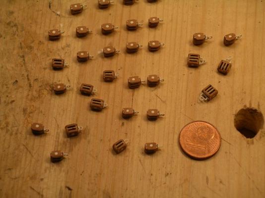
-
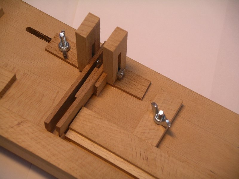
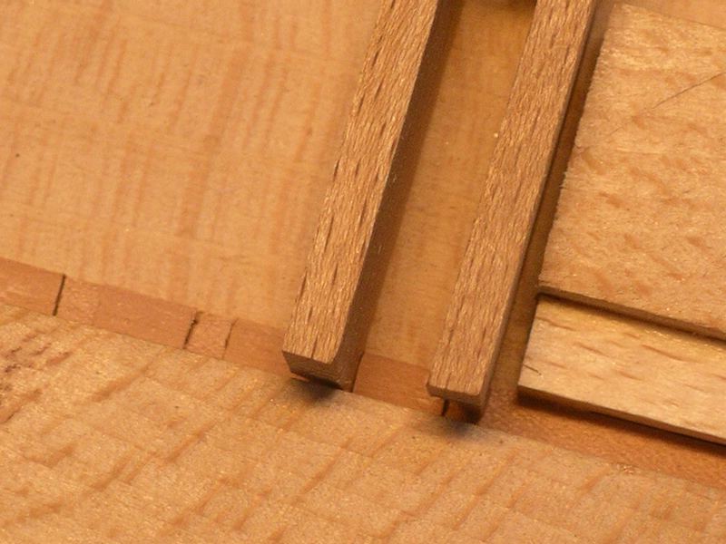
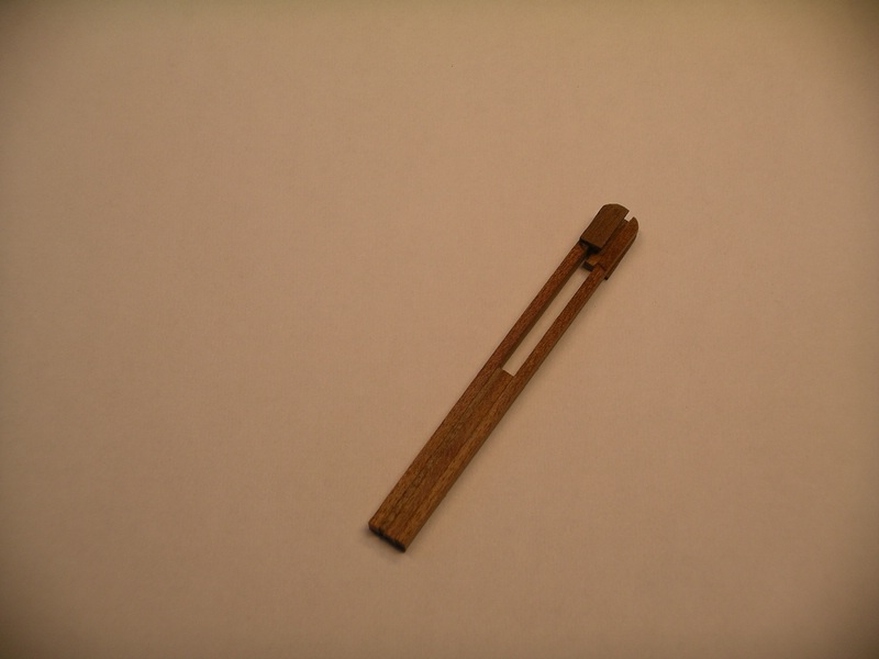
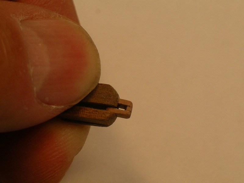
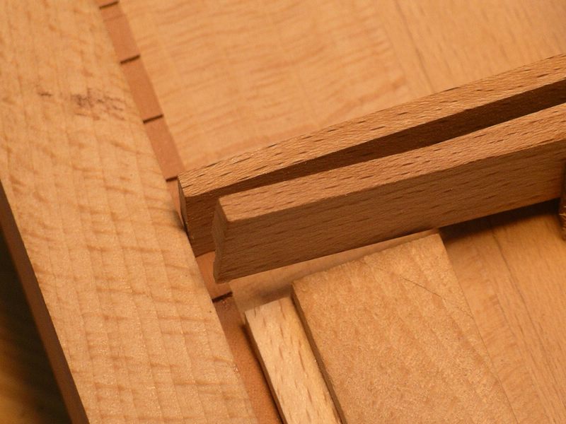
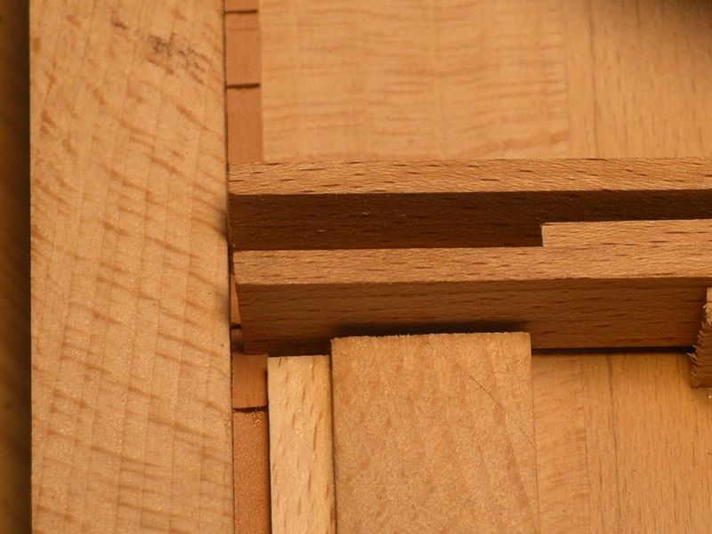
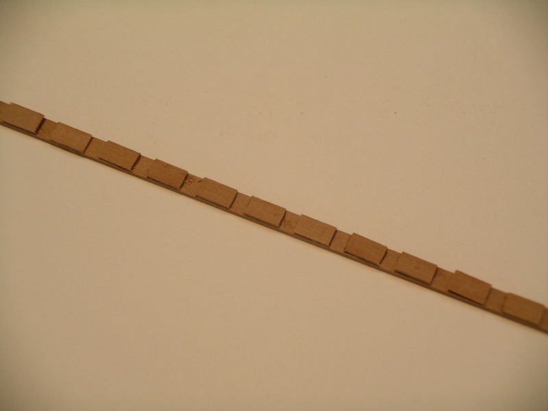
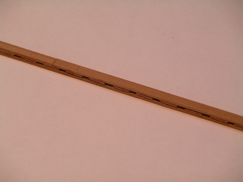
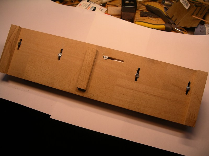
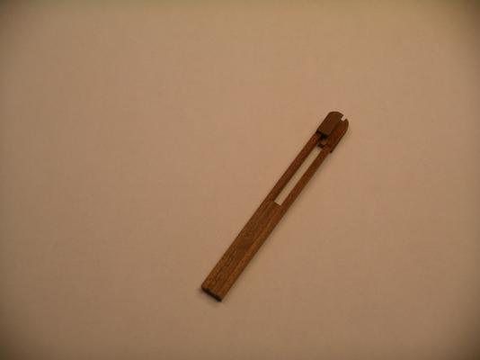
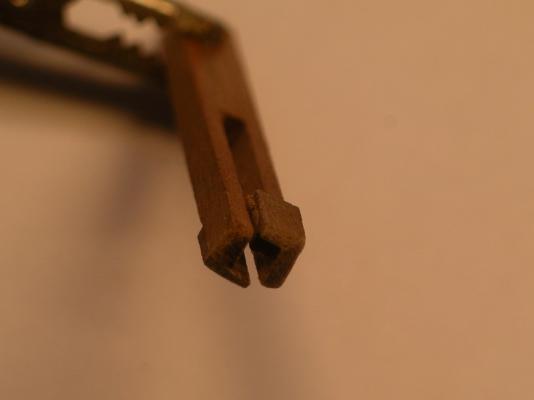
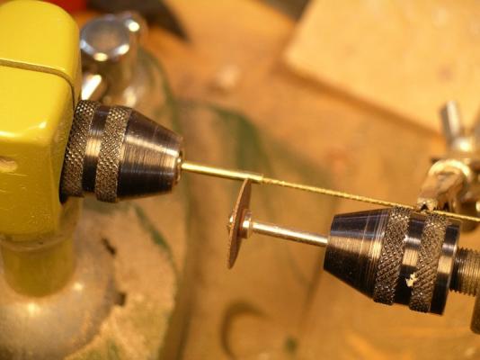
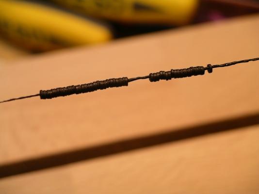
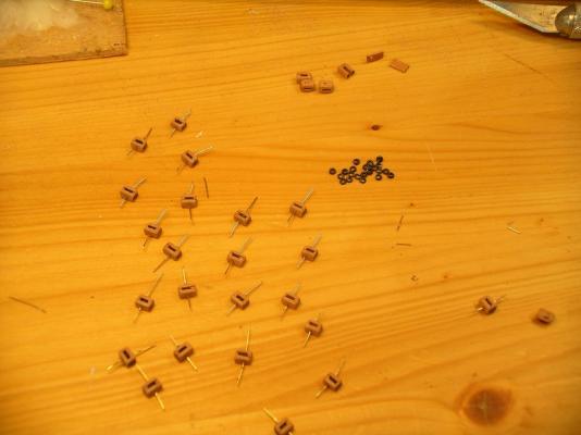
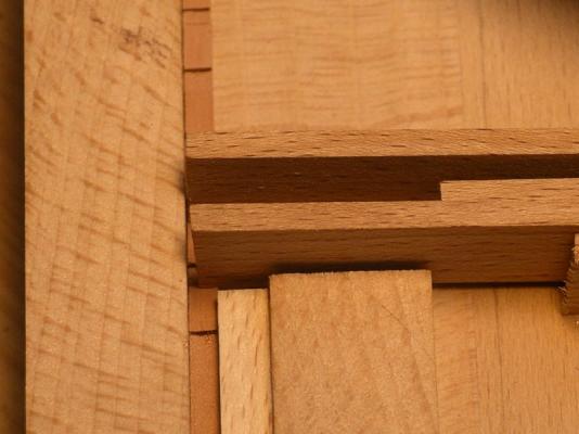
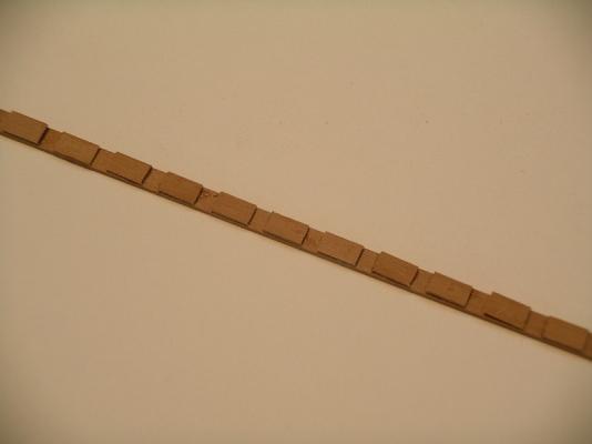
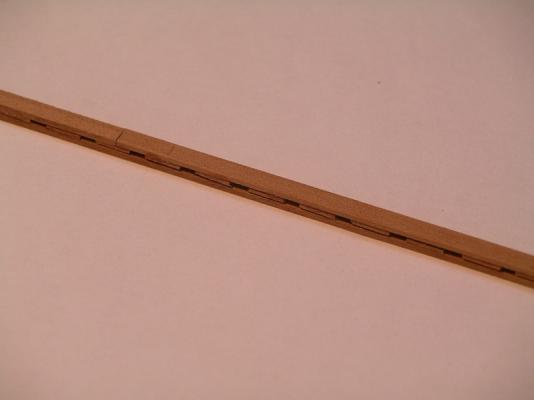
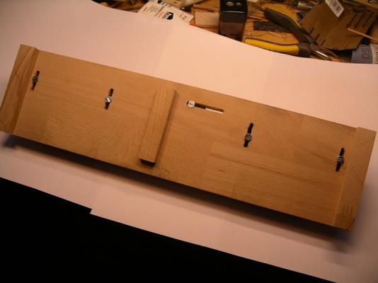
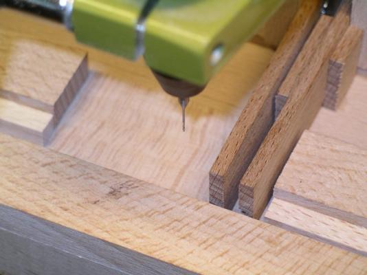
So, now is the specific production of the first batch of medium sized blocks of 4.2 mm length and 3.5 mm width. As the first images, the strip of the side wall is passed through the mount described above and adhered the strip portions. The fourth picture then shows the result with the glued-second sidewall. After the holder is attached to the once inserted, glued strips in drill stands, the axles are drilled. The bars are cut longitudinally into the desired shape. In this case the corners are substantially rounded. Then the blocks are separated one by one. It is always to the front of the first ground that rounding before the block itself is separated. After separation of the block that needs to be clamped in a small holder, because he is too small to be kept clean with your fingers can. Then the other side of the block to be ground. Small inset: The prepared holder has two small strips with each other on one side with spacers (slightly larger than the block to be held) are bonded, and thereby can be bent slightly. Front then ran small strips and inside on one side a depth limitation. Even a block can be inserted and firmly pressed with two fingers. For the rolls/pulleys I use a brass tube with the correct thickness and cut small parts from it. For this, the tube is clamped in a drilling machine, which then rotates at not too high speed, in the tube is a wire, which holds a holder, which serves not fly the sections thereof. With a second machine now the parts are cut off. Then the roles are blackened. After that, finishing with inserting the rollers, introduction and bonding of the axes, which are then separated according to later and sanded on each block is done. On one side a short pin is glued to a metal eye then. In the last step, the roller axles are painted and indicated the other screws through points. It is in this case to something more modern blocks as they are used mainly in Amerigo used. And now I hope that this type of blocks to make mobile heads, and is still successful in the remaining variables. Bye Joachim


-
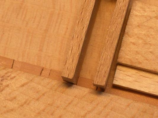
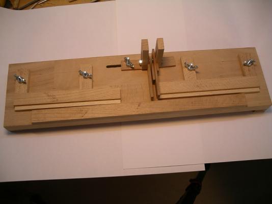
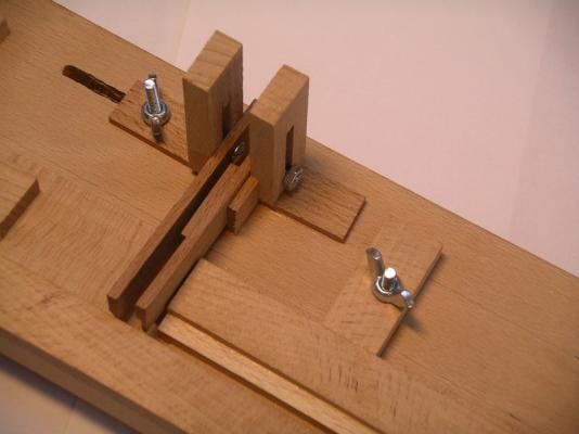
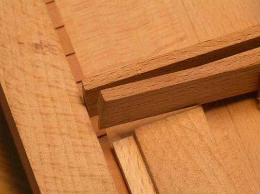
Hi guys, now that my summer vacation is already history again and the daily routine has caught me again, I will slowly continue with the AV. Before I can fix the masts, a whole lot of blocks must first be installed, as this is only possible with difficulty afterwards. So it goes to the manufacture of blocks of different size, shape, and with 1-3 pulleys Overall, I need 500-600 blocks of wood and in addition there are a number of metal blocks. After trying a few different ways to block production, I want to introduce a new method, which I will now try to follow through. Any type of milling a slot has been found with my tools as not feasible. So I had the idea of the blocks in the different layers that make them up, build up, so the side walls and walkways in between. First of all, the strips are cut in the width of the later blocks and polished to the desired thickness. For the parts inbetween, the corresponding strips are cut in equally long sections (in this case, about 6mm). In order to produce a greater number of the blocks a bit easier, I've build a holder. Along a stop to the strip are routed out of the blocks then be created. To run the strip exactly, there are two movable parts on the support bars that provide the right distance. Then there's a fixed-position stop with a movable stop bar and an equally designed sliding fence. Now, first, the first strip which forms the side walls, is inserted into the holder and the first small portion adhered thereto with quick-setting adhesive. Then the stop bars are positioned so far and found that it is possible to stick the other strip lengths each with the exact same distance from each other. The distance is chosen so that between them there is a gap where later to run the pulleys. If you insert this bar with the glued sections back into the holder, can now partially (to achieve a good bond), the bar for the other cheek to be adhered thereto. Due to the lead in the bracket fit each other exactly. Thereafter, the strips are glued together in turn inserted into the holder and it can be accurately drilled holes for the hubs of the rollers. In order to clamp the bracket itself in the drill stand is glued to the bottom of the bracket for a toolbar. More ... It's the same in the next post ...

-
Hi Michael, happy Birthday Thanks a lot showing us some pictures from you and your shipyard! Bye Joachim
-
Hi Michael, after beeing back from my long summer holiday it really took a long time to read through lots of pages with wonderful pictures of your Wasa! I must repeat it again, an amazing and fantastic build and step by step I am learning more about the Wasa. I am looking forward to the next update. Regards, Joachim
-
Thank you Michael, A bientôt Joachim
-
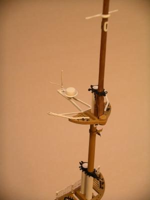
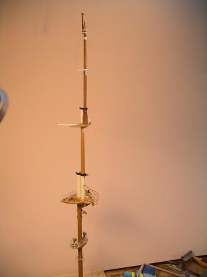
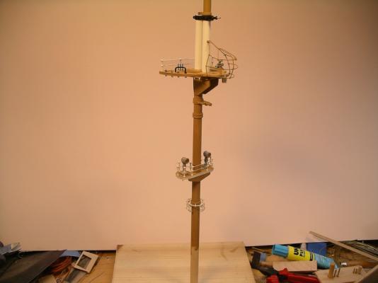
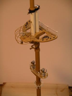
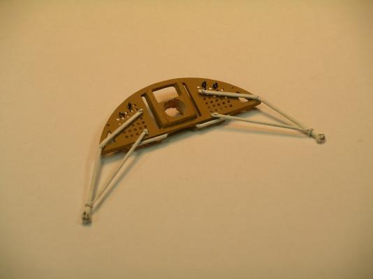
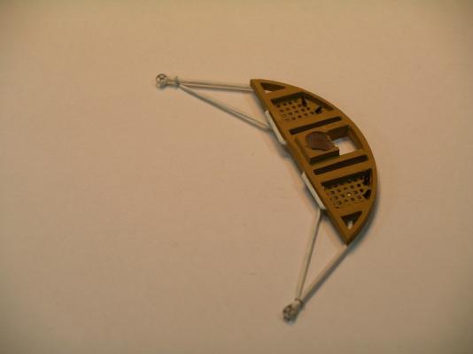
And Now, this is the result of the puzzle.... The mizen mast ist build similar to the other masts. Additionally there is another spar behind the mast, where the gaff is pulled up. Also there is an additional holder fixed to the cross-tree which contains modern Radar and radio navigation equipment. There are still missing a few parts but I've not quite finished getting, because early tomorrow morning we go for a few weeks with the caravan to southern France at the Mediterranean Sea! See you soon, Bye Joachim
-
Thank you Slog... oh I like my shipyard, but sometimes it could be bigger Joachim
-
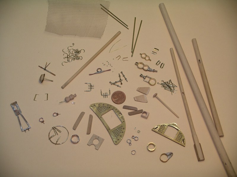
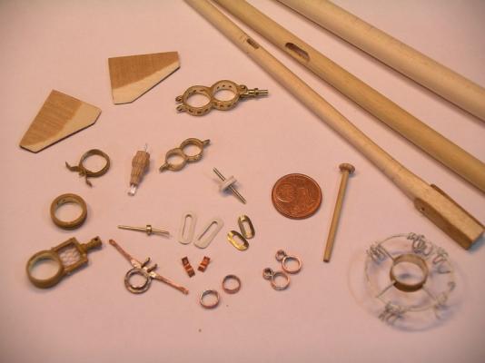
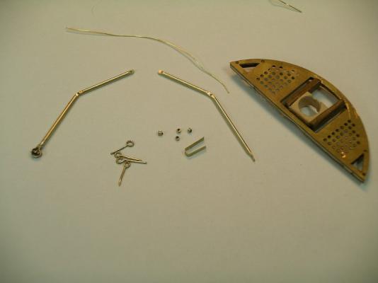
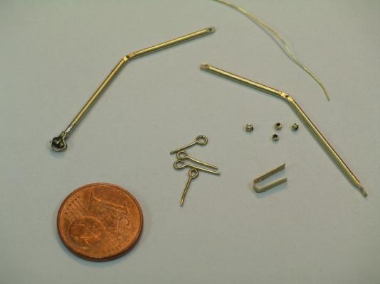
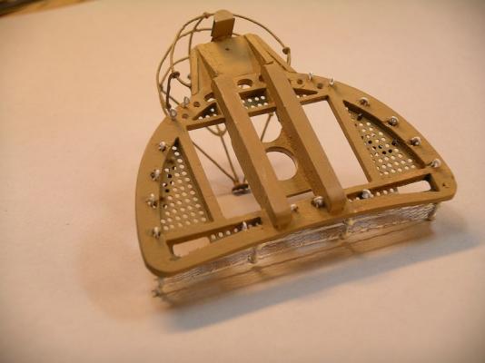
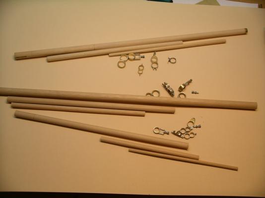
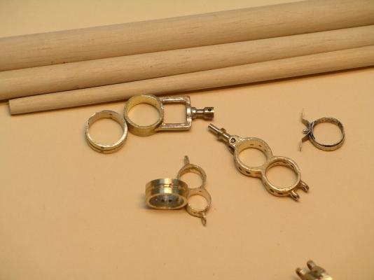
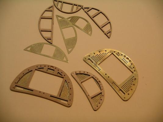
Hello, today only a picture with all basic parts of which the mizen mast consists of. After finishing this, of course there are needed further parts on all masts. Lots of small parts to be soldered, and always these difficulties handling the small parts,... e.g. the pulleys with only 1mm diameter ... Bye Joachim
-
Really wonderful, detailed and very accurate work!! Due to all the canons, there will be left only a few space on the decks. I am looking forward to the moment, when all canons will be installed, must be great. Regards, Joachim
-
Thanks Michael, my wife likes this ship. The book you mentioned is also available in German (that's easier for me ) and it got very good write-up's, so I think I'll try it. The only problem ist, there are still waiting lots and lots of books to be read, so, maybe it takes a bit time... Bye Joachim
-
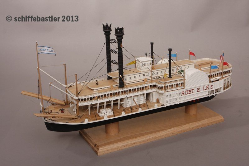
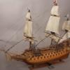
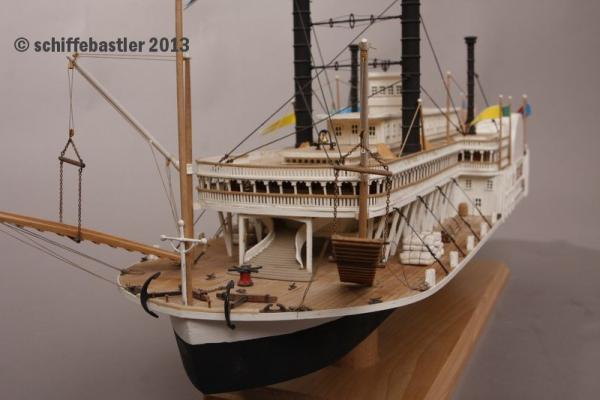
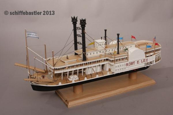
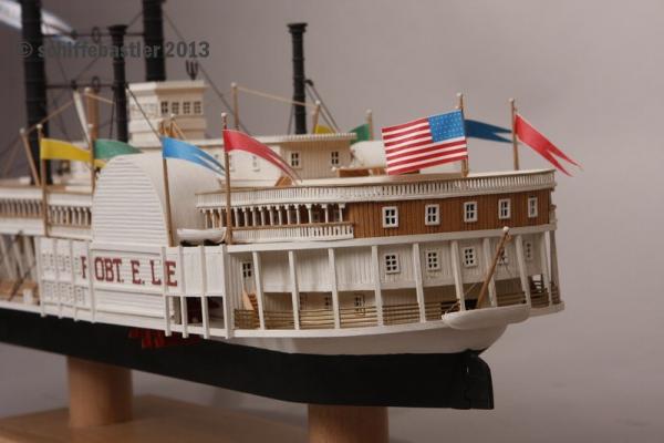
Thanks a lot Wacko, Gary and Michael! Michael, sounds interesting the books, maybe I'll order it, just found at Amazon. You have really good eyes, noticing the Mississippi steamer But the box you can see on the picture is empty, but here I can show you a few pictures of the completed model. Regards, Joachim
-
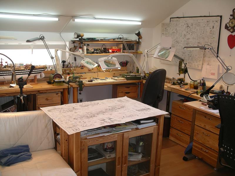
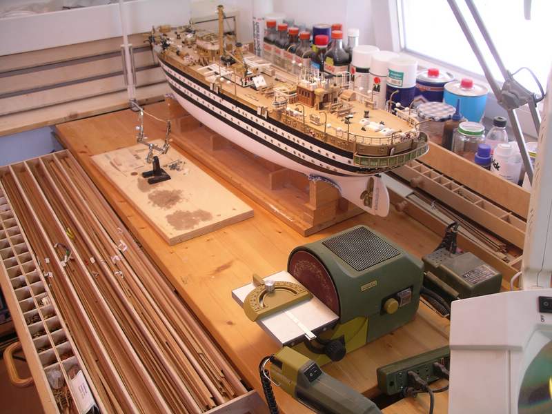
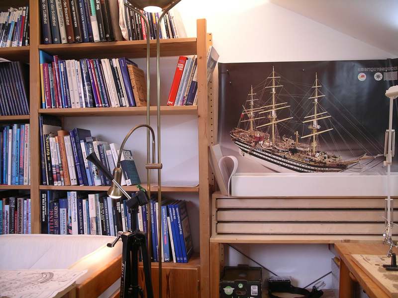
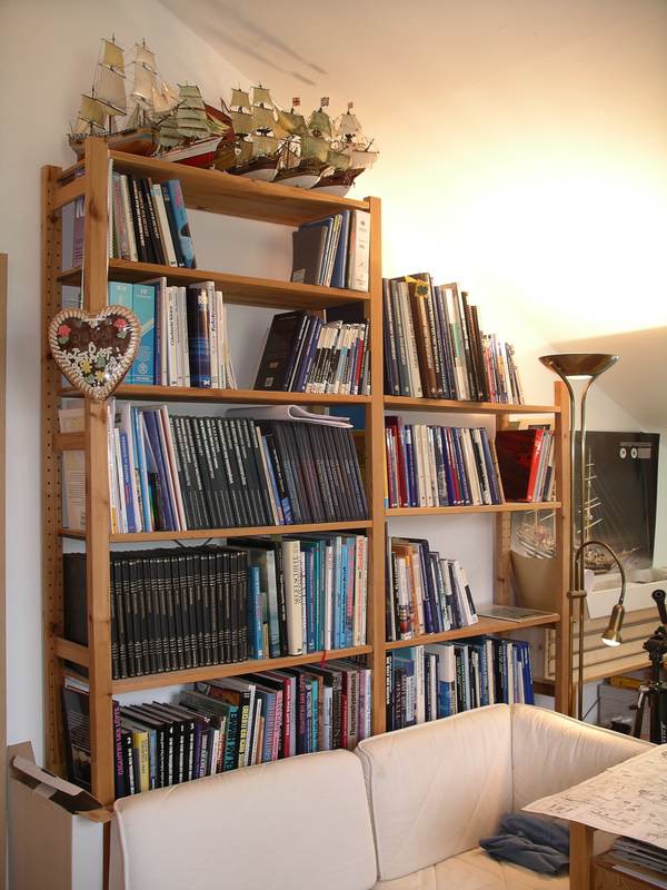
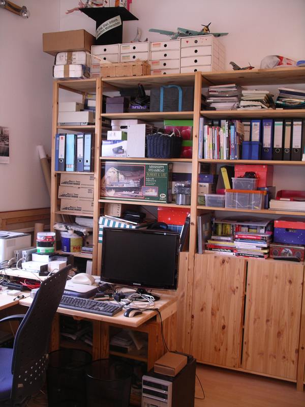
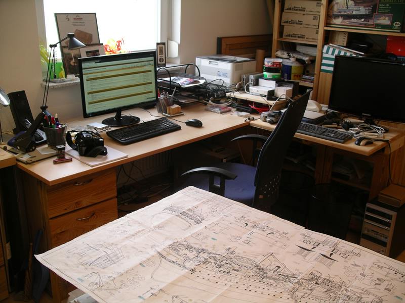
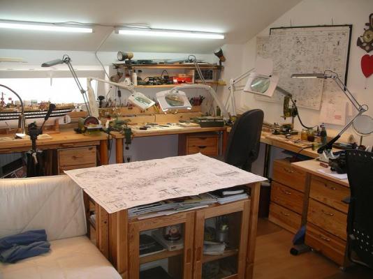
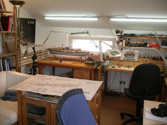
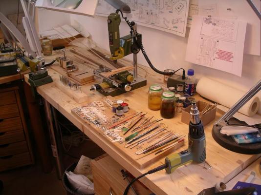
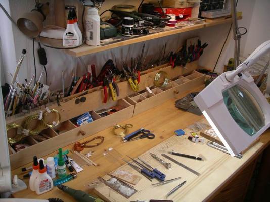
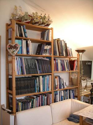
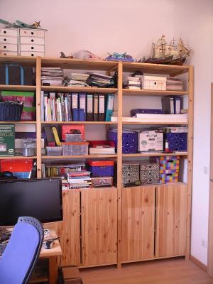
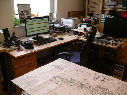
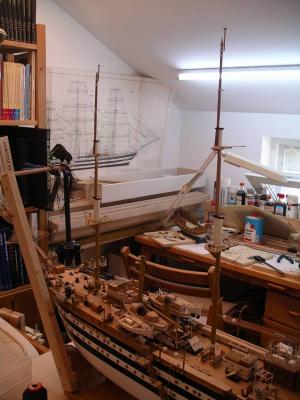
Thank you very much Michael and also dafi for the likes ! By the way, this is how the whole shipyard looks like,a quick look around ... shipyard, some hundred ship-books, my old plastic ships, electronics and computer ... Joachim


-
Thanks a lot, Wacko and to all giving me your notifications ! Bye Joachim
-
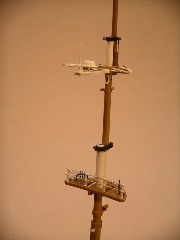
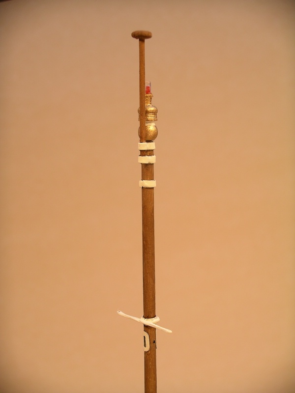
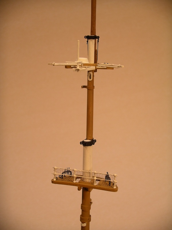
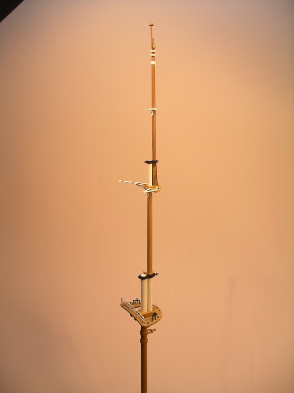
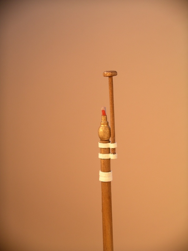
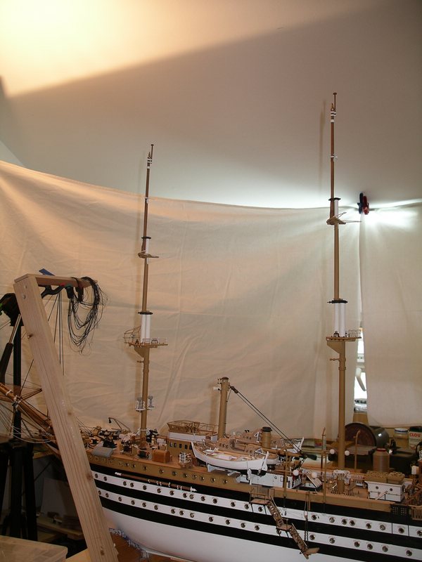
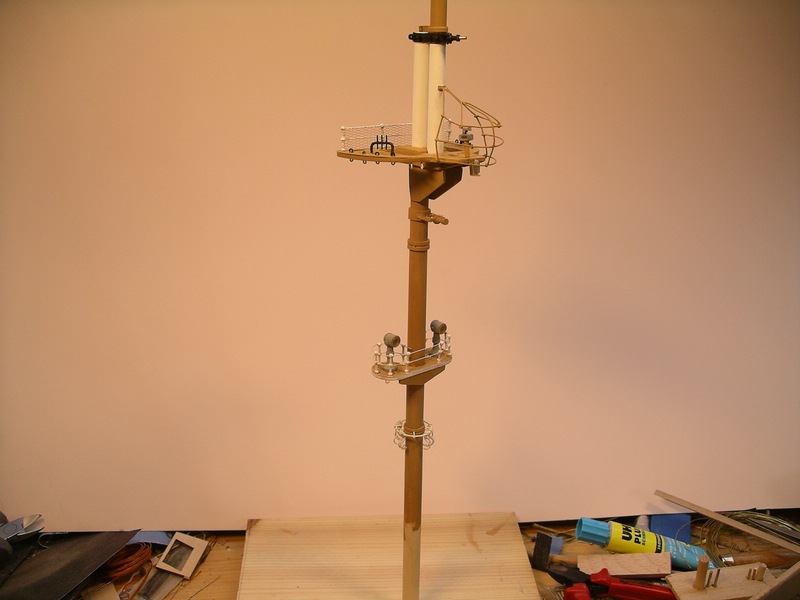
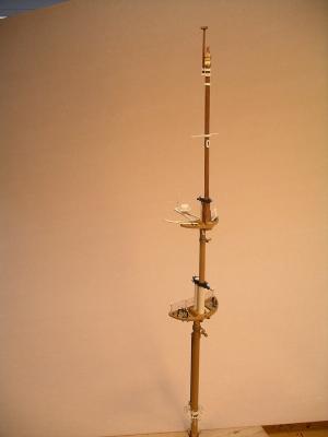
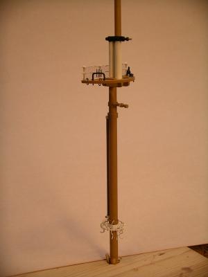
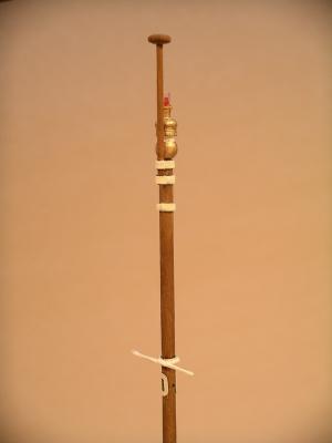
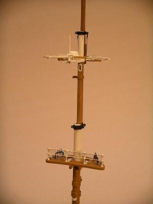
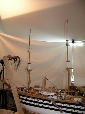
Hello everybody, during summer of course there are a lot of other things to do, but some progress has been done. The mainmast is ready so far. The construction is similar to the foremast. Therefore now only pictures from the ready assembled mast. first an overall view This is a holder mounted above the height of the mast bettings is used to hang surplus ropes Now the mars next the saling Halfway up between spreader and masthead is a kind of small spreader, the function of me but so far is not yet clear On the masthead then something laterally offset the flagpole Had tried to make an overall view of the provisionally inserted masts, the photographic result is however quite bad ... if all masts are finished then I'll have to go to the photo studio ... Now I will start with the third and last mast. Bye Joachim


-
Hello Nils, Michael, Gary, thank you all very much for your kind words! Regards Joachim
-
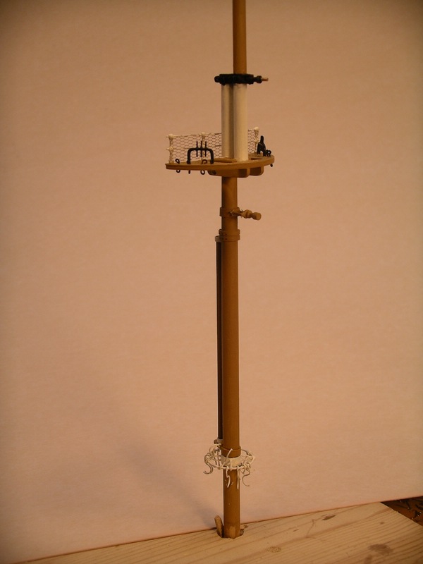
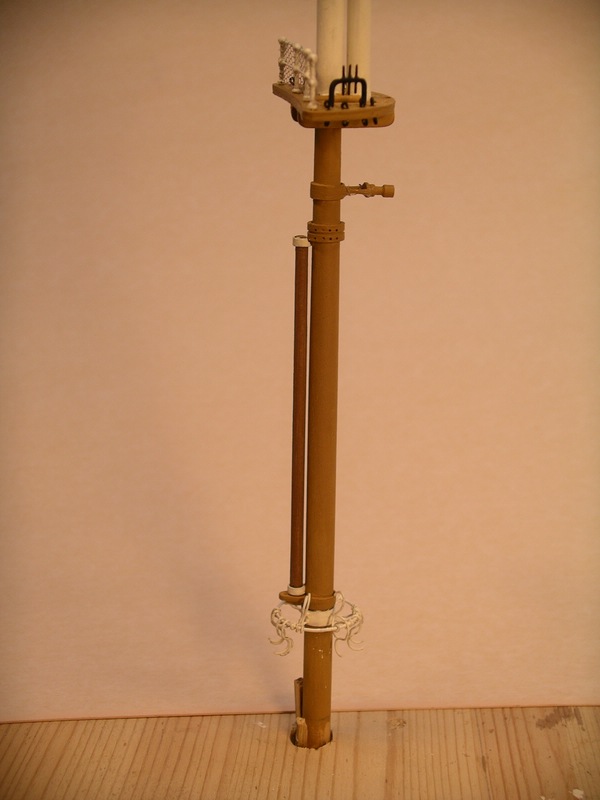
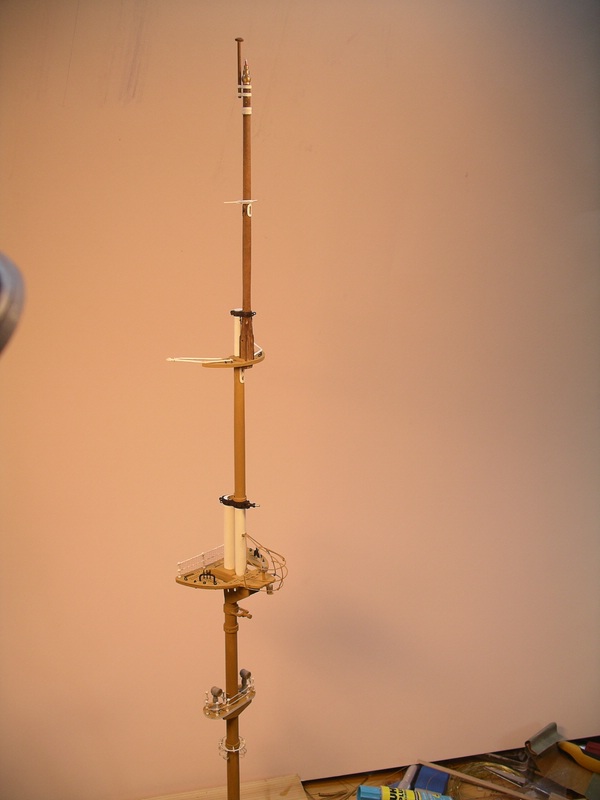
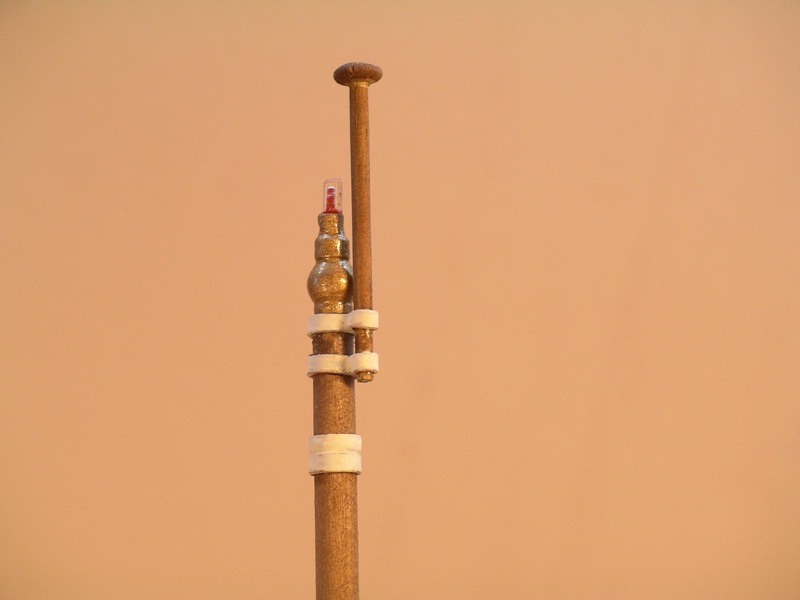
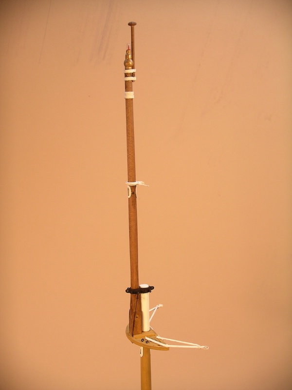
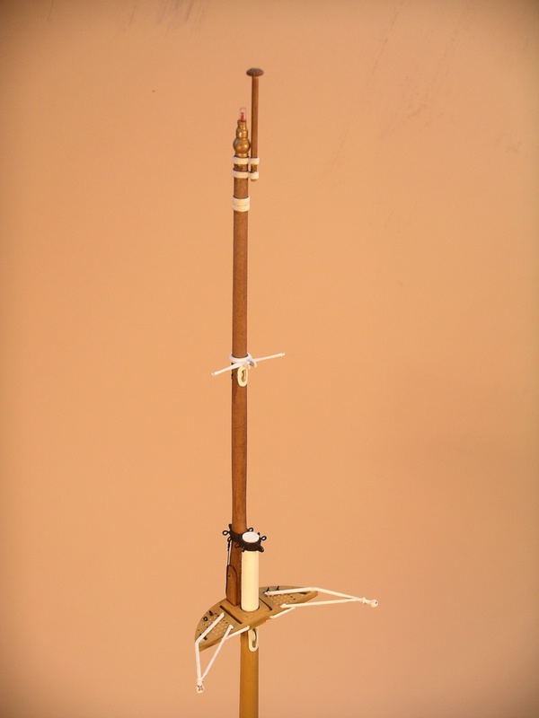
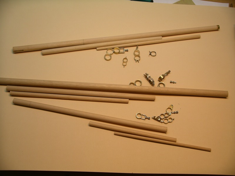
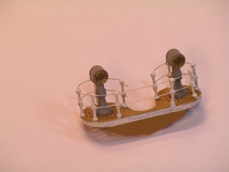
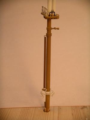
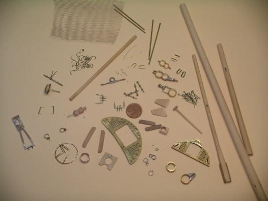
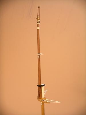
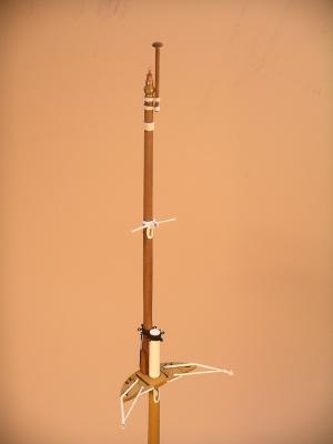
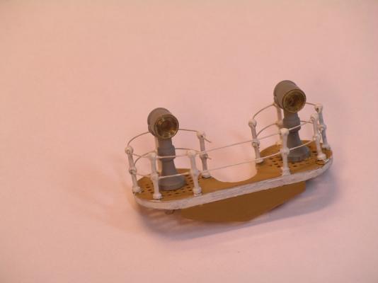
Hello everybody, now, after my two weeks sailing trip, I will show you the result of my work just before my holidays. The foremast is assembled now. Some small details are still missing, but beside of this ... First a small collection of the bigger parts, the mast consists of ... And so it looks like, assembled together ... here a feaw pictures from the lower mast with the extra platform for signal lamps ... At the saling there are a few interesting parts: through the bottom of the topgallant mast there is a diagonal incision through which there leads a steel cable which is fixed at the mast cap on both sides. By veering this cable, the topgallant mast can be let down. You can see this on the real ship in the following links. http://www.congedativespucci.it/galleria/camp2008/112.html http://www.congedativespucci.it/galleria/camp2008/126.html http://www.congedativespucci.it/galleria/camp2008/127.html In addition to the previous pictures, I had to correct the saling a bit, because the saling consists of a rounded part in front of it, where a opening is inside, up to the mast. Through this opening a big wooden block is pressed in order to fix the topgallant mast in position. Also to the right and left of the mast the wooden blocks fix the mast. At top of the mast there is fixed a flagstaff, a bit to the side. Through the cap of the flagstaff are going 2x2 holes through which halyards for the flags run through. Now a few pictures from the upper mast. Within the topgallant mast there is also a pulley for the halyard of the topgallant yard. Directely below the saling there is another pulley for the halyard of the upper top sail yard. The halyard of the royal yard is lead through a block (which has alreade to be build) on the side of the top of the mast. Now I can continue with the other masts. Bye, Joachim


-
Thank you so much Michael for your nice comment! And many thanks to all, giving me likes! Regards, Joachim
-
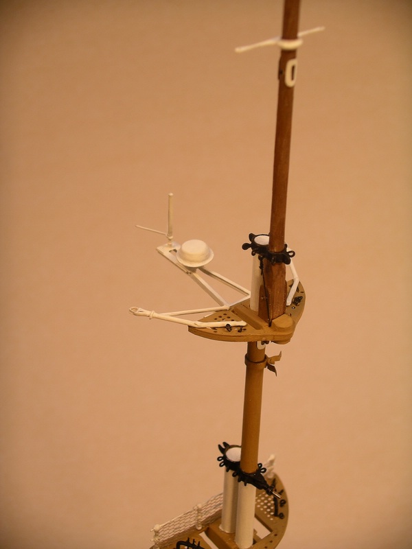
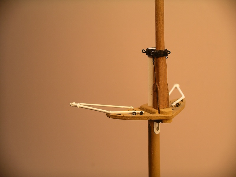
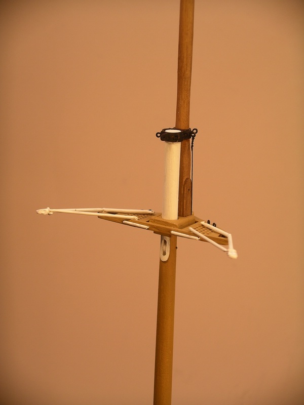
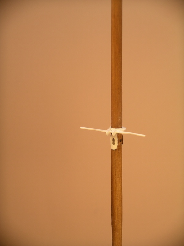
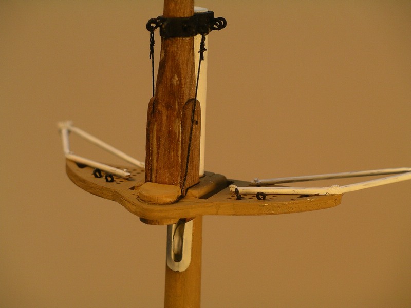
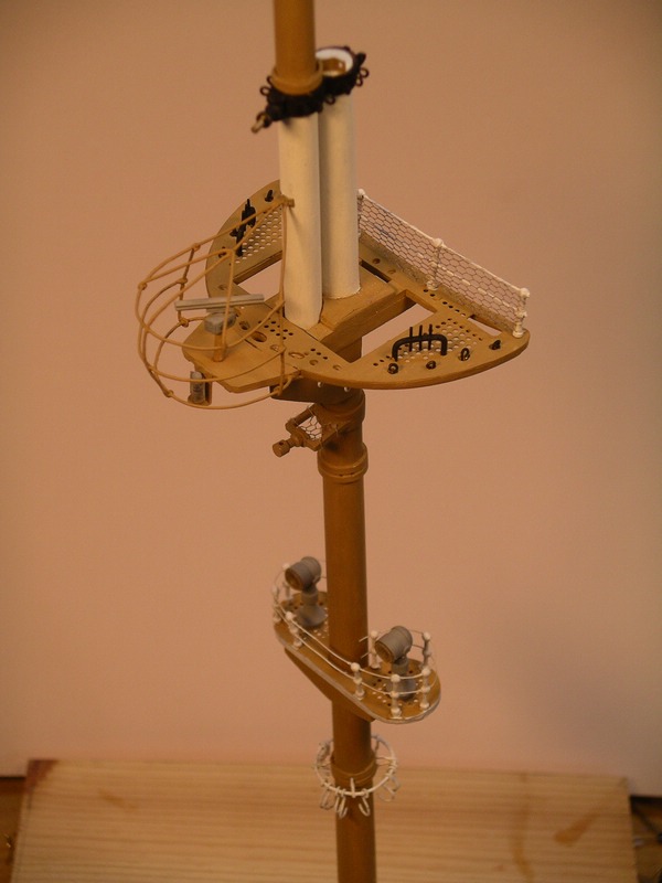
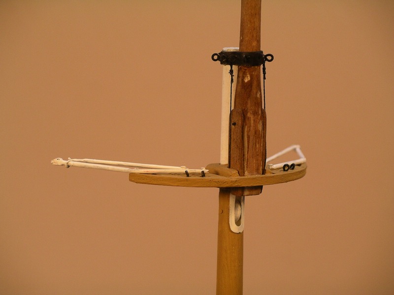
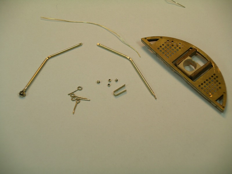
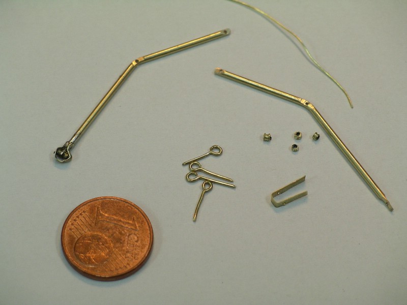
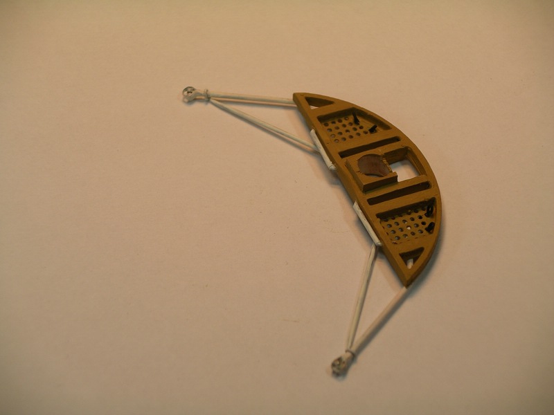
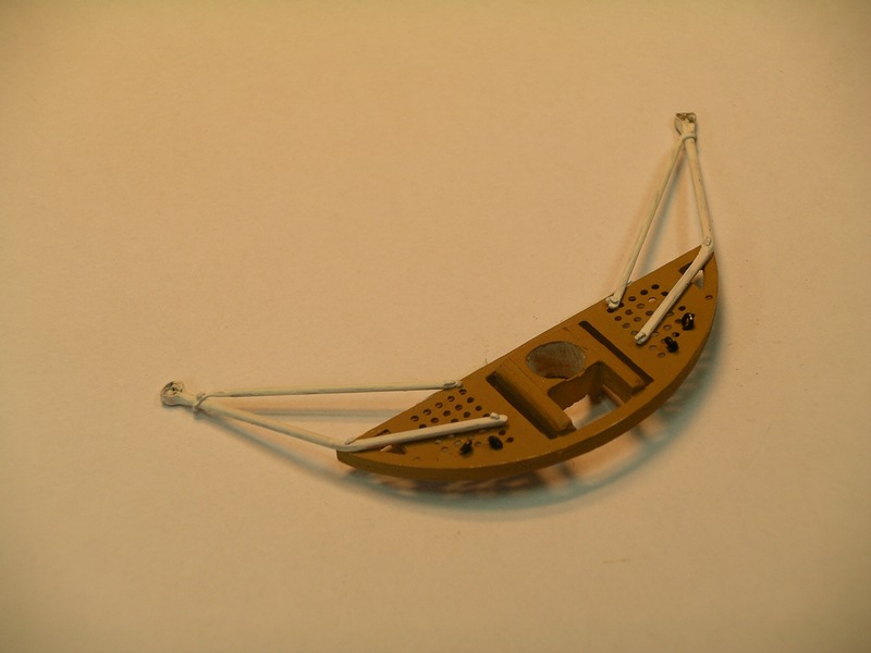
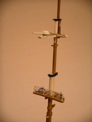
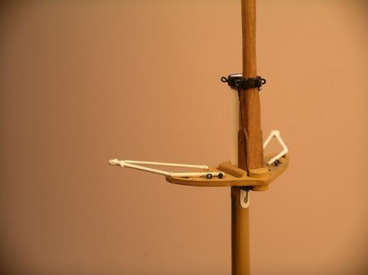
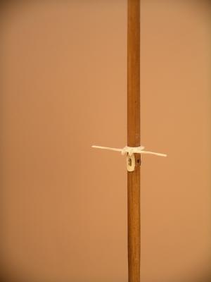
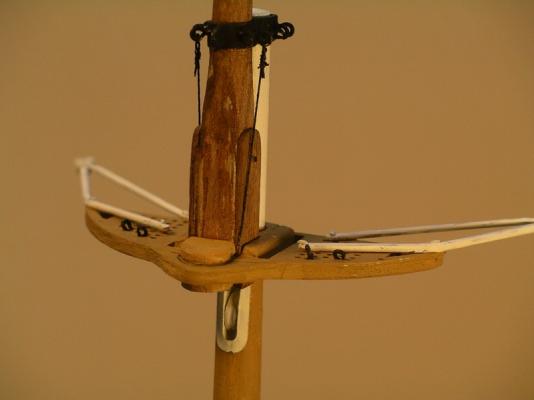
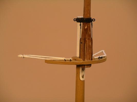
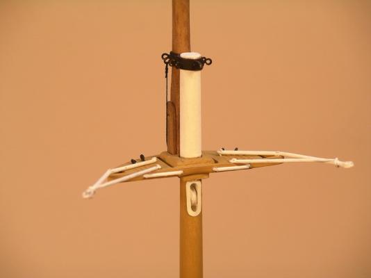
The next part ist the saling of the foremast. On the platform of the saling are jibs on both sides of boom mounted which serve to spread the backstays side. At the end of the boom two small rollers are mounted over which the backstays are performed. In the model, the rollers have a diameter of 1 mm. And so does it look: So far for today Bye, Joachim
-
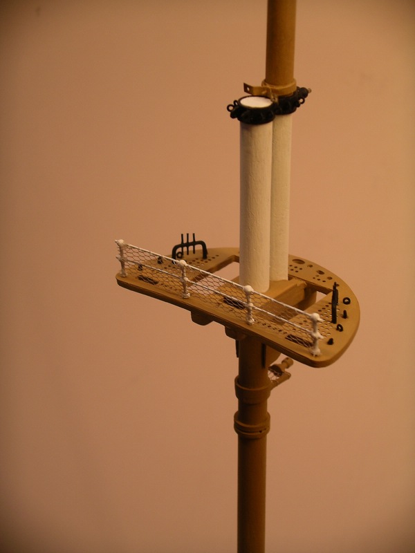
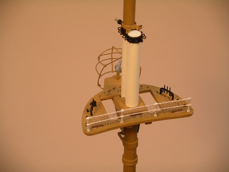
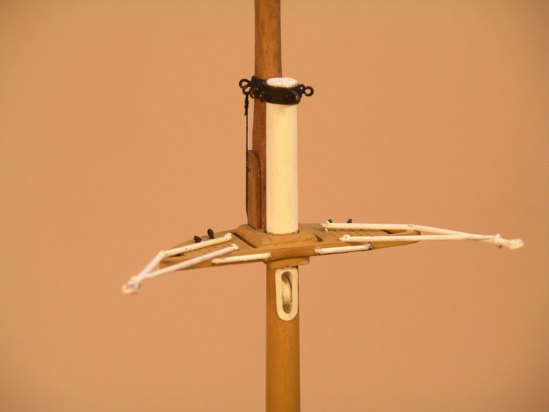
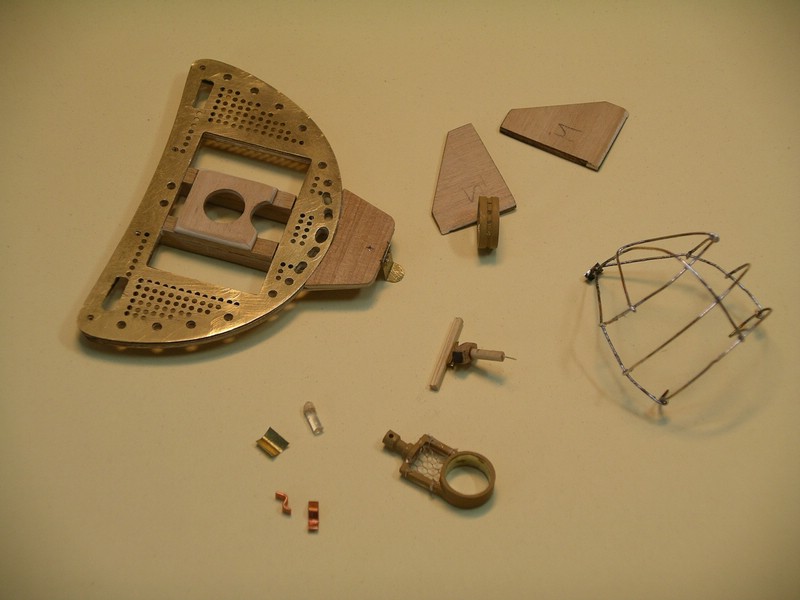
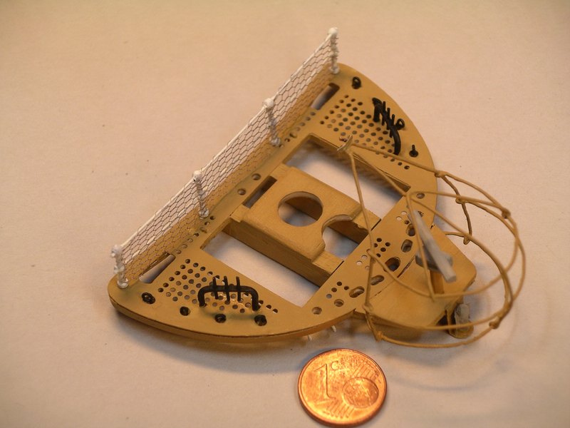
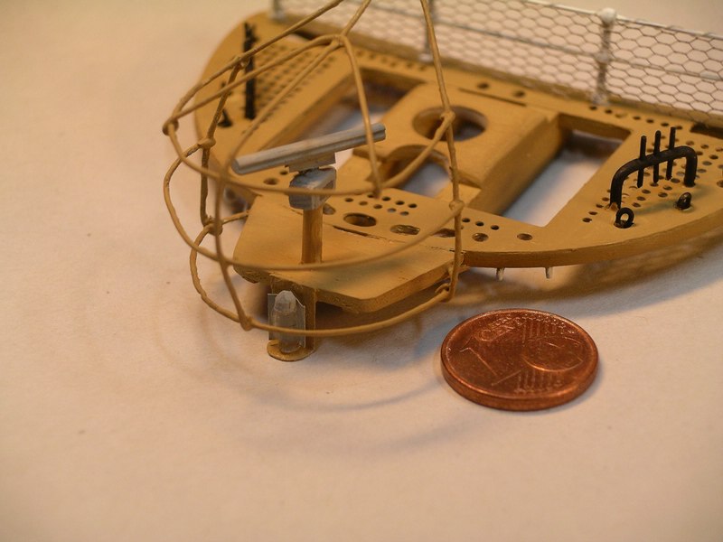
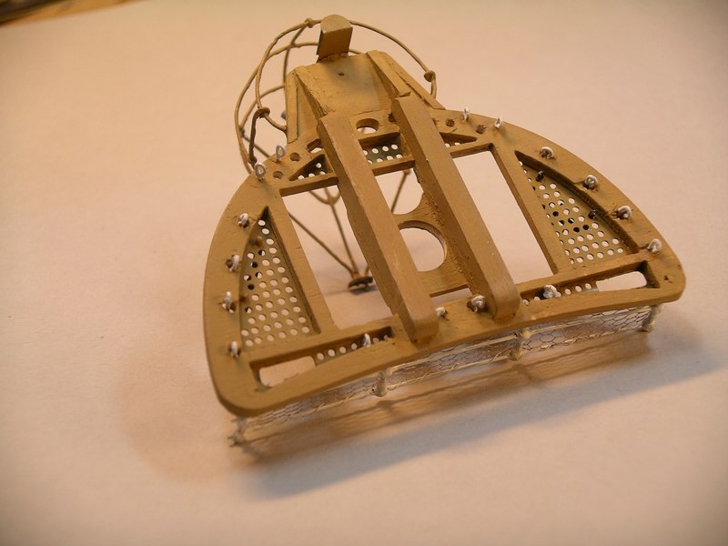
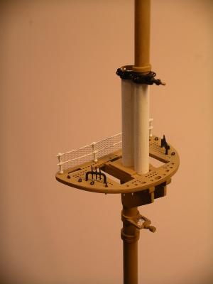
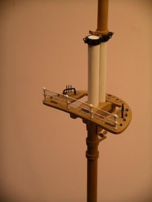
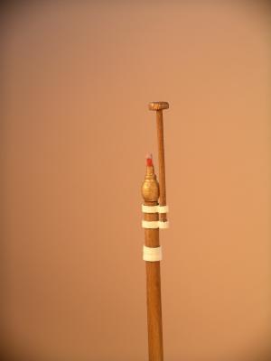
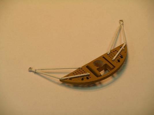
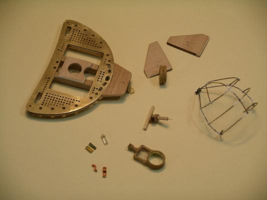
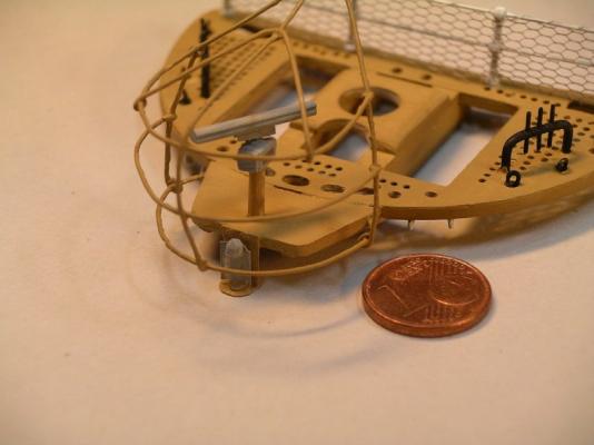
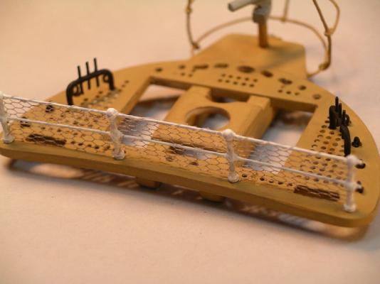
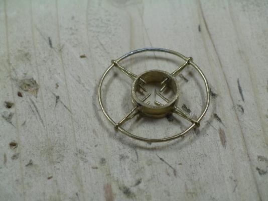
Now it's to the mars of the foremast. At the front of the mars a radar system is housed, which is protected by a tubular structure (was a sh ... soldering), before that, hangs a position light. The attached at both sides on the Mars there is a black metal bracket with three belaying pins for the uphauls of the top three yards. This is at the Amerigo somewhat different than other sailing ships in recent times. Bye, Joachim

-
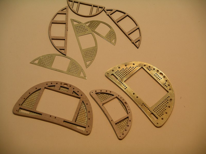
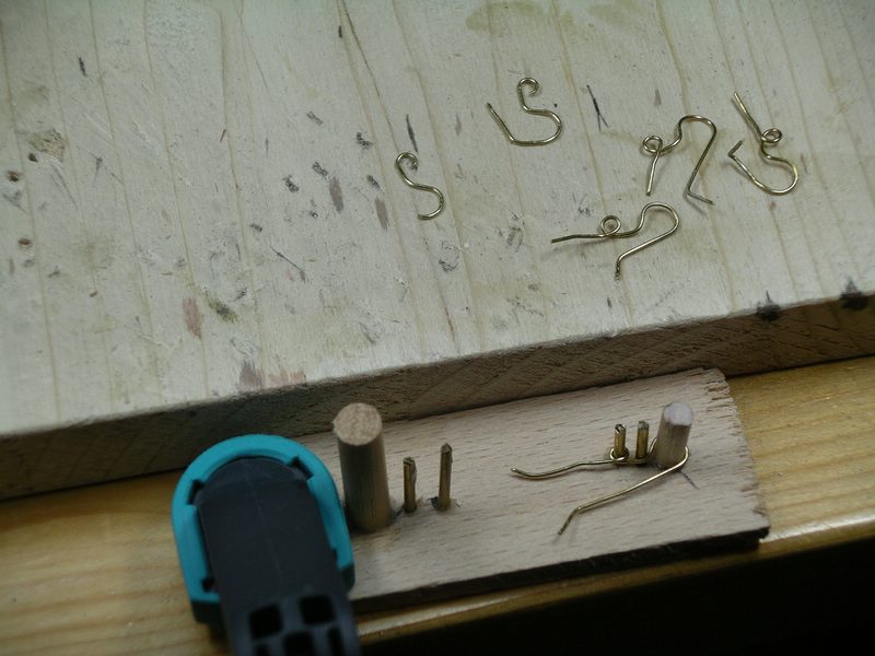
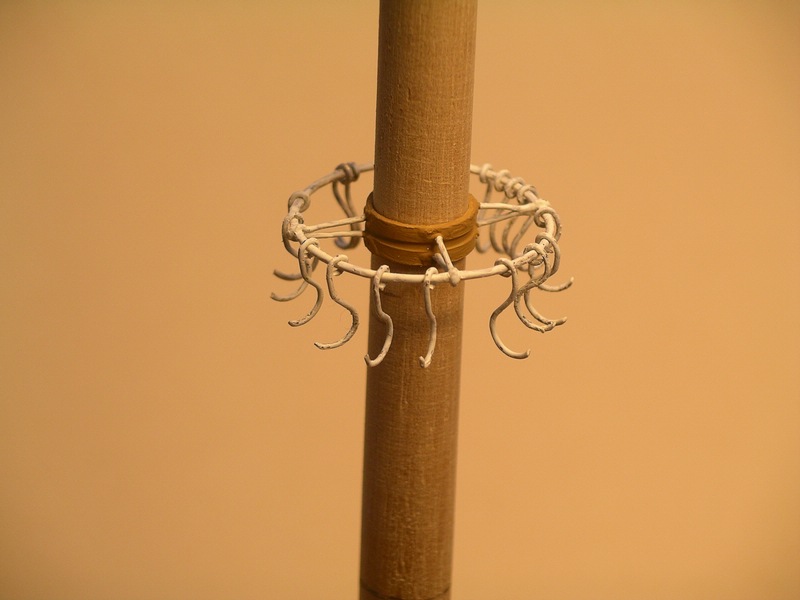
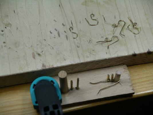
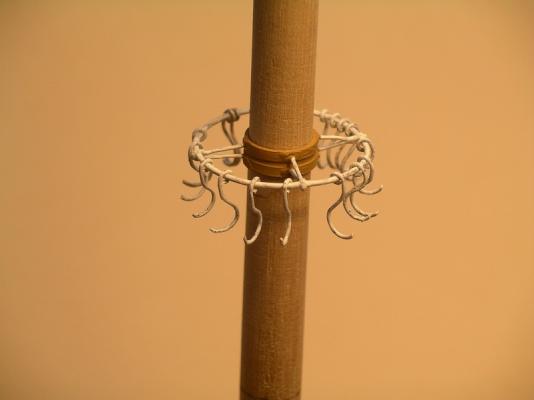
Hi Greg, thanks a lot for your nice commen! Hello everybody, in the meantime, the mast spars are cut, even ground for the foremast, also still made some blanks. Then soldered together a few parts. Halfway up the lower mast there is fixed a platform for large signal lamps. Then I build a mount which is attached to the lower mast and to be hooked onto the large hooks. In these large hooks are later suspended the excess cloth from the pin rails in large loops. For the production, there was a bit of soldering for the holder and a small auxiliary structure for the hook. Bye Joachim
-
Beautiful canons !! They look so realistic, well done! regards, Joachim
-
Thank you Richard! I am looking forward to see new pictures from your AV, I am sure, it will be great. Regards, Joachim