


_SalD_
-
Posts
815 -
Joined
-
Last visited
Reputation Activity
-

 _SalD_ got a reaction from Aussie048 in Phantom by _SalD_ - FINISHED - 1/8" scale
Chainplates done!
My first thoughts when I read Chuck’s practicum on how to make these plates was ‘you've got to be kidding! ’ But taking some advice of one of my old professors, I had a good cry over how this is impossible and there’s no way I can do this and then got down to solving the problem. After two trial attempts on some scrap brass strips and three failed attempts at the real thing I finally came up with a method that worked fairly well for me.
Some of the problems I had while working on the trial pieces was getting the drill bit to bite into the brass while at the same time trying to keep the holes in line and spaced properly. I tried using a punch (brad) but all that did was dent the strip and it was still hard to line up the punch marks. What I finally came up with to keep the holes in line was to scribe a line down the middle of the brass strip with a steel point. I discovered later while drilling the holes that this not only helped with keeping the holes in line but also made it easier for the drill to bite into the brass. To mark the location of each hole I made another scribe mark perpendicular to the center one. This in effect made a center mark for the drill bit. Once I made one plate that I was satisfied with I used it as a template for all the others.
Below are some of the other steps I preformed while making the chainplates.
1. Filed down the top portion of the plate that will form the hook at the top. Found it easier to work with the entire brass strip and not cut it to size until I was finished with the piece.
2. Form the hook using a needle nose pliers and bent it around the tip of a pin. At this point I test fit the hook into the hole on the caprail and marked where the first bolt hole should be located.
3. Marked the bolt hole location, one at a time, and drilled the hole. Repeated for the other two holes.
4. Marked the end of the plate and sniped it off the strip.
Note that all the scribe marks were done on the back of the plate. And sorry for rambling on so.
-
_SalD_ got a reaction from Aussie048 in Phantom by _SalD_ - FINISHED - 1/8" scale
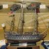
I've completed all the pieces and installed the wheel house, cockpit coaming, companionway and the stove pipe.
The coaming pieces were a bit out of shape and needed to be bent to the shape shown on the plans. While doing the wheel house I noticed that the length of the shaft on the ship’s wheel was not very long and thought I might have a problem installing it over the coaming. To give the wheel more clearance I filed down the two coaming pieces to form a notch where the wheel house is located. I also decided to install a baseboard around the base of the coaming that matched the wheel house and companionway. Before installing the baseboard I filed down the metal rigid along the base of the coaming. I pre-bent and stained the wood strips before gluing them in place.
I actually forgot the two bollards with the cleats were provided with the kit and didn’t remember until after I had started to make them (senior moment). I liked the the ones I started so I decided not to use the ones provided. I made them from the 1/16” square wood strip, cut to the length taken from the plans. For the cleats I notched the bollard and inserted a small piece of wood.
I decided to use the grating that is provided although it’s rather large for this scale. The only modification I made was to sand it down so it wasn't so thick. I glued the pieces together prior to sanding it and then cut it to shape.
The wooden seat on top of the coaming was made from a piece of the 1/32” thick wooden sheet. Before cutting the seat out I sanded the piece down to about 1/64” so the seat wouldn't be so thick. I also notched this piece at the wheel house to match the coaming.
For the inside of the cockpit I used a piece of manila folder painted white.
After all the pieces were made I finally got to put it all together. I had to keep telling myself to be patience and let everything dry before starting. Even so I think the ploy on the grating was still a little tacky when I glued it down. I'm glad I notched the coaming and seat because the wheel never would have fit if I didn't.
The stove pipe was painted black and the guard was made out of the 28 gage black wire. Took the pipes location from the plans a drilled all the appropriate holes for it and the guard.
-
 _SalD_ got a reaction from Littlebob in Phantom by _SalD_ - FINISHED - 1/8" scale
I've completed all the pieces and installed the wheel house, cockpit coaming, companionway and the stove pipe.
The coaming pieces were a bit out of shape and needed to be bent to the shape shown on the plans. While doing the wheel house I noticed that the length of the shaft on the ship’s wheel was not very long and thought I might have a problem installing it over the coaming. To give the wheel more clearance I filed down the two coaming pieces to form a notch where the wheel house is located. I also decided to install a baseboard around the base of the coaming that matched the wheel house and companionway. Before installing the baseboard I filed down the metal rigid along the base of the coaming. I pre-bent and stained the wood strips before gluing them in place.
I actually forgot the two bollards with the cleats were provided with the kit and didn’t remember until after I had started to make them (senior moment). I liked the the ones I started so I decided not to use the ones provided. I made them from the 1/16” square wood strip, cut to the length taken from the plans. For the cleats I notched the bollard and inserted a small piece of wood.
I decided to use the grating that is provided although it’s rather large for this scale. The only modification I made was to sand it down so it wasn't so thick. I glued the pieces together prior to sanding it and then cut it to shape.
The wooden seat on top of the coaming was made from a piece of the 1/32” thick wooden sheet. Before cutting the seat out I sanded the piece down to about 1/64” so the seat wouldn't be so thick. I also notched this piece at the wheel house to match the coaming.
For the inside of the cockpit I used a piece of manila folder painted white.
After all the pieces were made I finally got to put it all together. I had to keep telling myself to be patience and let everything dry before starting. Even so I think the ploy on the grating was still a little tacky when I glued it down. I'm glad I notched the coaming and seat because the wheel never would have fit if I didn't.
The stove pipe was painted black and the guard was made out of the 28 gage black wire. Took the pipes location from the plans a drilled all the appropriate holes for it and the guard.
-
 _SalD_ got a reaction from ScottRC in Phantom by _SalD_ - FINISHED - 1/8" scale
I've completed all the pieces and installed the wheel house, cockpit coaming, companionway and the stove pipe.
The coaming pieces were a bit out of shape and needed to be bent to the shape shown on the plans. While doing the wheel house I noticed that the length of the shaft on the ship’s wheel was not very long and thought I might have a problem installing it over the coaming. To give the wheel more clearance I filed down the two coaming pieces to form a notch where the wheel house is located. I also decided to install a baseboard around the base of the coaming that matched the wheel house and companionway. Before installing the baseboard I filed down the metal rigid along the base of the coaming. I pre-bent and stained the wood strips before gluing them in place.
I actually forgot the two bollards with the cleats were provided with the kit and didn’t remember until after I had started to make them (senior moment). I liked the the ones I started so I decided not to use the ones provided. I made them from the 1/16” square wood strip, cut to the length taken from the plans. For the cleats I notched the bollard and inserted a small piece of wood.
I decided to use the grating that is provided although it’s rather large for this scale. The only modification I made was to sand it down so it wasn't so thick. I glued the pieces together prior to sanding it and then cut it to shape.
The wooden seat on top of the coaming was made from a piece of the 1/32” thick wooden sheet. Before cutting the seat out I sanded the piece down to about 1/64” so the seat wouldn't be so thick. I also notched this piece at the wheel house to match the coaming.
For the inside of the cockpit I used a piece of manila folder painted white.
After all the pieces were made I finally got to put it all together. I had to keep telling myself to be patience and let everything dry before starting. Even so I think the ploy on the grating was still a little tacky when I glued it down. I'm glad I notched the coaming and seat because the wheel never would have fit if I didn't.
The stove pipe was painted black and the guard was made out of the 28 gage black wire. Took the pipes location from the plans a drilled all the appropriate holes for it and the guard.
-
_SalD_ got a reaction from Aussie048 in Phantom by _SalD_ - FINISHED - 1/8" scale
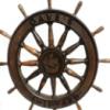
I reopened the shipyard this past weekend and started to work on the deck fixtures. Made the wheel house from the ¼”x ½” stock and cut it to dimensions taken from the plans. I then sanded the top to the appropriate slope and radius. After painting the piece white I used some of my scale lumber for the roof and baseboard trim. The lumber was stained prior to gluing it to the wheel house. Finally, I drilled the hole for the ship’s wheel that will be painted and installed later.
The wheel house was only placed on the deck; I want to complete the cockpit coaming and companionway before gluing them all in place.
-
_SalD_ got a reaction from Aussie048 in Phantom by _SalD_ - FINISHED - 1/8" scale
Here’s my interpretation of the cockpit companionway. I cut a 1” long piece of ¼” x ½” stock for the main body and sanded it down to the sloped shape. For the roof and sliding top I used more of the dimensional lumber. I installed the curved edge strips first and then placed the roof slats in between them. The rails for the sliding top were made from two pieces of lumber glued into an 'L' shape. I finished it off with the base board trim pieces. The only thing I need to add is the hasp lock.
-
 _SalD_ got a reaction from Mirabell61 in Phantom by _SalD_ - FINISHED - 1/8" scale
Here’s my interpretation of the cockpit companionway. I cut a 1” long piece of ¼” x ½” stock for the main body and sanded it down to the sloped shape. For the roof and sliding top I used more of the dimensional lumber. I installed the curved edge strips first and then placed the roof slats in between them. The rails for the sliding top were made from two pieces of lumber glued into an 'L' shape. I finished it off with the base board trim pieces. The only thing I need to add is the hasp lock.
-

-
_SalD_ reacted to SawdustDave in Mayflower by SawdustDave - Finished
Whilst we're in this sharing mode, here's a little collage of the tool caddies I use to keep from going nuts reaching for the right tweezers, snips, file, knife, pliers, hole drill, saw, or whatever else we tend to accumulate over the years.
-
_SalD_ got a reaction from ScottRC in Phantom by _SalD_ - FINISHED - 1/8" scale
Started working on the launching ways. Cut all the pieces and stained them. Made up a little jig to set the cross timbers.
Also painted the hull and marked the waterline. Almost ready to copper the hull. I wanted to finish the launching ways first so I could locate and drill the holes in the keel for the mounting pins.
-
 _SalD_ got a reaction from trippwj in Phantom by _SalD_ - FINISHED - 1/8" scale
Here’s my interpretation of the cockpit companionway. I cut a 1” long piece of ¼” x ½” stock for the main body and sanded it down to the sloped shape. For the roof and sliding top I used more of the dimensional lumber. I installed the curved edge strips first and then placed the roof slats in between them. The rails for the sliding top were made from two pieces of lumber glued into an 'L' shape. I finished it off with the base board trim pieces. The only thing I need to add is the hasp lock.
-
_SalD_ got a reaction from ScottRC in Phantom by _SalD_ - FINISHED - 1/8" scale
Here’s my interpretation of the cockpit companionway. I cut a 1” long piece of ¼” x ½” stock for the main body and sanded it down to the sloped shape. For the roof and sliding top I used more of the dimensional lumber. I installed the curved edge strips first and then placed the roof slats in between them. The rails for the sliding top were made from two pieces of lumber glued into an 'L' shape. I finished it off with the base board trim pieces. The only thing I need to add is the hasp lock.
-
_SalD_ reacted to FlounderFillet5 in Phantom by FlounderFillet5 - Model Shipways - Pilot Boat
Why hello again, it has been about six months since my last update and that is mostly due to not doing much building... until now! I hope you all have been doing well. I have made a bit of progress since my last update.
First, here are pictures of the cap rail. Basically, I used my thinning jig to thin the cap rail blank down to approximately 1/64" of an inch. Then I just carved out the inside and, this time, it fit properly so I glued it into place.
Next, I decided to modify the eye bolts and cleats to make them closer to being in scale. All I did for the eye bolts was take some pliers and bent the wire into a smaller loop, cut them to a proper length, and blackened them.
As for the the cleats, this was a few step process:
(from left to right)
- Untouched cleat
- Cut/file off the little tab at the bottom
- Make a center hole with an awl for drilling
- Drill an appropriate diameter hole that will fit the eye bolt wire, I think I used a #78 drill bit but don't quote me on that.
- Glue an eye bolt into the drilled hole and let glue set (These were cut first and then the eye bolts were made from the remaining end)
- File down the cleat until it is closer to scale size (I left these oversized (out of scale) a bit because I figure I am going to need some extra area on them for the rigging line.
- Cut the wire so that it protrudes about the thickness of your bulwark stanchions (Not pictured)
Here are the cleats all done and ready to be installed.
Next, I drilled holes in the appropriate bulwark stanchions (found on the plans) with the same size drill bit used on the cleats.
Here are pictures of the eye bolts, cleats, and cap rail installed.
That is the progress I made over the past few months. Let me know what you guys think!
My next post will be the progress I made this weekend.
-
_SalD_ got a reaction from Aussie048 in Phantom by _SalD_ - FINISHED - 1/8" scale
Chainplates were installed following Chuck's practicum. One thing I found easier to do was to pull the thread that is hooked onto the chainplate through the hole in the caprail from the top down and then hook on the chainplate and pull the thread and chainplate back up into the hole. I used a pin that I bent the tip on to push up through the hole in the caprail and then catch it on the tread to pull it down through the hole. I then drilled the holes in the hull for the nails to secure the chainplates. Tying the deadeyes to the chainplates was an experience.
Next I located and drilled the holes in the caprail for the belaying pins and eye bolts and glued them in place. All the belaying pins, eye bolts and chainplates were blackened prior to installation. I decided to keep all the deadeyes and blocks their natural color.
I also made an installed the traveler. I pretty much followed the practicum except that I soldered the legs to the top of the traveler.
This will be my last post on my build for the next two weeks. The shipyard will be shutdown while the admiral and I go for a little R&R in the sunshine state.
-
 _SalD_ got a reaction from SawdustDave in Mayflower by SawdustDave - Finished
Dave, at least he went on the paper. Isn't that suppose to be good luck or something?
-
_SalD_ reacted to Dziadeczek in How to Taper Masts?
For a better controlled process, build yourself a simple jig. Get 2 paint mixing sticks (for free from Home Depot), cut them to appropriate lengths (slightly longer than the length of your mast) and glue to each on one side a strip of medium grade sand paper.
At one end of such stick glue short piece of wood (spacer) of same thickness as the top of your mast, and at the opposite end glue two other spacers as thick as the bottom diameter of your mast, leaving center hole empty. Glue both sticks together. Especially helpful if you fabricate many identical parts.
Clamp your jig to the worktable.
Insert one end of your dowel into a chuck of a handheld drill and place the opposite end of the dowel into this center hole of your jig. Start your drill and gently press it into your jig, until it goes all the way. It will be stopped by the smaller spacer at the other end. Voila!
I saw this concept in the Polish shipmodeling forum - one modeler was fabricating a few dozen oars for his model. You can see it here (scroll down the page half way to see appropriate pics).
http://www.koga.net.pl/forum/viewtopic.php?f=7&t=44911&p=57251&hilit=galera#p57251
-
 _SalD_ got a reaction from hexnut in Phantom by _SalD_ - FINISHED - 1/8" scale
Chainplates done!
My first thoughts when I read Chuck’s practicum on how to make these plates was ‘you've got to be kidding! ’ But taking some advice of one of my old professors, I had a good cry over how this is impossible and there’s no way I can do this and then got down to solving the problem. After two trial attempts on some scrap brass strips and three failed attempts at the real thing I finally came up with a method that worked fairly well for me.
Some of the problems I had while working on the trial pieces was getting the drill bit to bite into the brass while at the same time trying to keep the holes in line and spaced properly. I tried using a punch (brad) but all that did was dent the strip and it was still hard to line up the punch marks. What I finally came up with to keep the holes in line was to scribe a line down the middle of the brass strip with a steel point. I discovered later while drilling the holes that this not only helped with keeping the holes in line but also made it easier for the drill to bite into the brass. To mark the location of each hole I made another scribe mark perpendicular to the center one. This in effect made a center mark for the drill bit. Once I made one plate that I was satisfied with I used it as a template for all the others.
Below are some of the other steps I preformed while making the chainplates.
1. Filed down the top portion of the plate that will form the hook at the top. Found it easier to work with the entire brass strip and not cut it to size until I was finished with the piece.
2. Form the hook using a needle nose pliers and bent it around the tip of a pin. At this point I test fit the hook into the hole on the caprail and marked where the first bolt hole should be located.
3. Marked the bolt hole location, one at a time, and drilled the hole. Repeated for the other two holes.
4. Marked the end of the plate and sniped it off the strip.
Note that all the scribe marks were done on the back of the plate. And sorry for rambling on so.
-
_SalD_ got a reaction from Mirabell61 in Phantom by _SalD_ - FINISHED - 1/8" scale
Chainplates were installed following Chuck's practicum. One thing I found easier to do was to pull the thread that is hooked onto the chainplate through the hole in the caprail from the top down and then hook on the chainplate and pull the thread and chainplate back up into the hole. I used a pin that I bent the tip on to push up through the hole in the caprail and then catch it on the tread to pull it down through the hole. I then drilled the holes in the hull for the nails to secure the chainplates. Tying the deadeyes to the chainplates was an experience.
Next I located and drilled the holes in the caprail for the belaying pins and eye bolts and glued them in place. All the belaying pins, eye bolts and chainplates were blackened prior to installation. I decided to keep all the deadeyes and blocks their natural color.
I also made an installed the traveler. I pretty much followed the practicum except that I soldered the legs to the top of the traveler.
This will be my last post on my build for the next two weeks. The shipyard will be shutdown while the admiral and I go for a little R&R in the sunshine state.
-
_SalD_ got a reaction from hexnut in Phantom by _SalD_ - FINISHED - 1/8" scale
Chainplates were installed following Chuck's practicum. One thing I found easier to do was to pull the thread that is hooked onto the chainplate through the hole in the caprail from the top down and then hook on the chainplate and pull the thread and chainplate back up into the hole. I used a pin that I bent the tip on to push up through the hole in the caprail and then catch it on the tread to pull it down through the hole. I then drilled the holes in the hull for the nails to secure the chainplates. Tying the deadeyes to the chainplates was an experience.
Next I located and drilled the holes in the caprail for the belaying pins and eye bolts and glued them in place. All the belaying pins, eye bolts and chainplates were blackened prior to installation. I decided to keep all the deadeyes and blocks their natural color.
I also made an installed the traveler. I pretty much followed the practicum except that I soldered the legs to the top of the traveler.
This will be my last post on my build for the next two weeks. The shipyard will be shutdown while the admiral and I go for a little R&R in the sunshine state.
-
 _SalD_ got a reaction from bhermann in Phantom by _SalD_ - FINISHED - 1/8" scale
Chainplates done!
My first thoughts when I read Chuck’s practicum on how to make these plates was ‘you've got to be kidding! ’ But taking some advice of one of my old professors, I had a good cry over how this is impossible and there’s no way I can do this and then got down to solving the problem. After two trial attempts on some scrap brass strips and three failed attempts at the real thing I finally came up with a method that worked fairly well for me.
Some of the problems I had while working on the trial pieces was getting the drill bit to bite into the brass while at the same time trying to keep the holes in line and spaced properly. I tried using a punch (brad) but all that did was dent the strip and it was still hard to line up the punch marks. What I finally came up with to keep the holes in line was to scribe a line down the middle of the brass strip with a steel point. I discovered later while drilling the holes that this not only helped with keeping the holes in line but also made it easier for the drill to bite into the brass. To mark the location of each hole I made another scribe mark perpendicular to the center one. This in effect made a center mark for the drill bit. Once I made one plate that I was satisfied with I used it as a template for all the others.
Below are some of the other steps I preformed while making the chainplates.
1. Filed down the top portion of the plate that will form the hook at the top. Found it easier to work with the entire brass strip and not cut it to size until I was finished with the piece.
2. Form the hook using a needle nose pliers and bent it around the tip of a pin. At this point I test fit the hook into the hole on the caprail and marked where the first bolt hole should be located.
3. Marked the bolt hole location, one at a time, and drilled the hole. Repeated for the other two holes.
4. Marked the end of the plate and sniped it off the strip.
Note that all the scribe marks were done on the back of the plate. And sorry for rambling on so.
-
_SalD_ got a reaction from Aussie048 in Phantom by _SalD_ - FINISHED - 1/8" scale
The crew finally came to a mutual agreement on the cap rail color and decided to go with a medium brown stain. I wanted a color that was not too dark so all the attachments to the rail would stand out more.
One problem I ran into and didn't realize it until after I installed the cap rail was that I didn't leave enough of an overhang on the outboard side of the bulwarks. While reading ahead in the practicum on how to make and install the chainplates for the deadeyes, I realized the amount of overhang I left (~1/32”) was not going to be enough to install the chainplates through. I thought about just cutting the plates into the bulwarks but thought I would have to cut them in too deep. My solution was, in lieu of making a new rail, to carefully cut the rail off, then split the rail at the stern so I could spread it out a little on each side and then reattached it to the bulwarks. Filled the gap with wood paste and stained it after it dried.
Made and installed the fairleads. I used a small brass strip left over from the pintles for its base and the thin wire from the kit. These were a bit of a challenge to solder. Blackened them and glued them in place.
Made and installed the splash rail. I formed the splash rail on a homemade jig made on a piece of ¾” pine. I had traced the shape of the cap rail onto a piece of cardboard before I installed it (the first time) to layout the splash rail, then used finishing nails to form the curve and push pins to hold the piece in place. I had soaked the wood strips for a few hours before putting them in the jig and then let them dry overnight. Sanded them down to shape, painted and glued them in place. I then filed the notch into the top of the rail.
I measured the location for the two masts from the plans and drilled the holes in the deck. On the advise of my brother-in-law, who is an avid sailor, I put a coin in the bottom of the mast hole, I figured I could use all the luck I can get.
-
_SalD_ got a reaction from Littlebob in Phantom by _SalD_ - FINISHED - 1/8" scale
Wayne, thanks for your continued support, and if you find a way to motivate your boys let me know so I can try it on my daughter.
Patrick, welcome back; hope you’re more relaxed. Glad you like the deck and the rail.
-
_SalD_ got a reaction from hexnut in Phantom by _SalD_ - FINISHED - 1/8" scale
A little indecision
The cap rail is complete but not installed. Having trouble deciding what color to paint or stain it. The admiral wants one color, the first mate wants another and the swabbie (moi) wants another. I know it’s my ship but sometimes you got to keep the admiral happy. This indecision however is sort of a blessing in disguise. I found it easier to mount the hawse pipe and the inboard eye bolts and cleats without the rail in place.
I marked the position of the hawse pipes from the plans and then drilled a pilot hole through the hull. Fortunately the drill bit came out right above the waterway. I then enlarged the hole using progressively larger bits. I then glued the hawse pipe to the hull and painted it. I also drilled the four other smaller holes through the bulwarks as mentioned in the practicum. I’m not really sure what these holes are for though.
I blackened the eye bolts prior to installing them. I also used the left over 1/16” square wood strip I used for the bulwark stanchions to test fit the eye bolts and cleats. This gave me a chance to determine the proper hole diameter required and it came in handy to cut the eye bolts to their proper length. I pushed the eye bolt stem through the wood strip and then snipped off the part protruding from the back.
At first I was going to use the cleats as they came in the kit. Then I held one near the stanchion that it was to be mounted on to see what it looked like. The thing looked like it belonged on the Titanic! Needless to say I filed them down a bit to make them look a little more realistic. They’re still a little large but will have to do. Painted them black and glued them in place.
-
 _SalD_ got a reaction from BETAQDAVE in Phantom by _SalD_ - FINISHED - 1/8" scale
Thanks Patrick, hope your feeling better.
Decking is complete.
I first tried cutting individual planks, 1/16” wide with the intention of planking the deck with them. This proved, however, a bit beyond my current skill level. What I opted to do was use scribed planking. Not the one that came with the kit but one I made myself. First I made two planking templates, one of the fore deck and one of the aft deck.
I then finished a sheet of basswood ,1/32” thick by 4” wide x 12” long with 4 coats of polyurethane. After the sheet had dried completely I taped the deck planking patterns onto the basswood and using a steel point, traced over the lines to score the wood. Next I painted the decks with a dark brown acrylic paint and them immediately wiped the paint off. The paint came off the polyurethaned areas but stayed in the scored lines. Finally I cut out each deck section.
I like the results but I think I may have scored the wood a little too deep because the caulking lines appear a bit too thick, or maybe I should have used a lighter color paint so they don’t stand out so much. I can't take credit for this method because I did read how to do it in a book whose title and author escapes me right now. Amended 5/28/14 - the book is 'The Built-up Ship Model' by Charles G. Davis pages 106 to 107.
I also chose to cut in the cockpit area and made a template for that planking as well.
-
 _SalD_ got a reaction from aliluke in Phantom by _SalD_ - FINISHED - 1/8" scale
The crew finally came to a mutual agreement on the cap rail color and decided to go with a medium brown stain. I wanted a color that was not too dark so all the attachments to the rail would stand out more.
One problem I ran into and didn't realize it until after I installed the cap rail was that I didn't leave enough of an overhang on the outboard side of the bulwarks. While reading ahead in the practicum on how to make and install the chainplates for the deadeyes, I realized the amount of overhang I left (~1/32”) was not going to be enough to install the chainplates through. I thought about just cutting the plates into the bulwarks but thought I would have to cut them in too deep. My solution was, in lieu of making a new rail, to carefully cut the rail off, then split the rail at the stern so I could spread it out a little on each side and then reattached it to the bulwarks. Filled the gap with wood paste and stained it after it dried.
Made and installed the fairleads. I used a small brass strip left over from the pintles for its base and the thin wire from the kit. These were a bit of a challenge to solder. Blackened them and glued them in place.
Made and installed the splash rail. I formed the splash rail on a homemade jig made on a piece of ¾” pine. I had traced the shape of the cap rail onto a piece of cardboard before I installed it (the first time) to layout the splash rail, then used finishing nails to form the curve and push pins to hold the piece in place. I had soaked the wood strips for a few hours before putting them in the jig and then let them dry overnight. Sanded them down to shape, painted and glued them in place. I then filed the notch into the top of the rail.
I measured the location for the two masts from the plans and drilled the holes in the deck. On the advise of my brother-in-law, who is an avid sailor, I put a coin in the bottom of the mast hole, I figured I could use all the luck I can get.