

bensid54
-
Posts
531 -
Joined
-
Last visited
Content Type
Profiles
Forums
Gallery
Events
Posts posted by bensid54
-
-
Thank you Jparsley it's almost there I have one maybe two more servos to install that I will do once I get the chance.
-
As far as reverse goes I can put in two more switches but before I go to that trouble I'll install an override switch to bypass those micro switches when I need to make a turn or reverse it long enough to stop or give me a bit of bow room, after sea trial then I will do corrective wiring if need be. Patrick the camera is on a mount attached to the servo at the front that I made which gives me the ability to pan up and down as far as left to right goes I just turn the whole machine, the controller has a stabilizing system for cameras but I don't use it because I want to know if it is banking or turning on command.
-
-
-
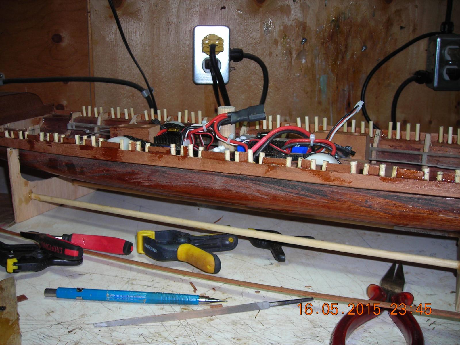
New video up with the micro switches installed, can you load it for me Patrick? I tried to interrupt the signal at the receiver but that didn't work so I ended up having to interrupt the positive lead on the motor, I think with some adjustments I should almost have the oar operation working right.
-
-
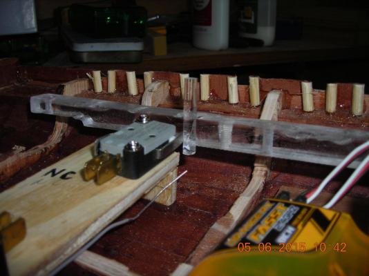
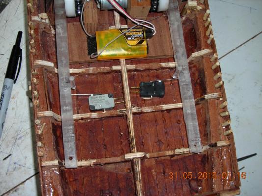
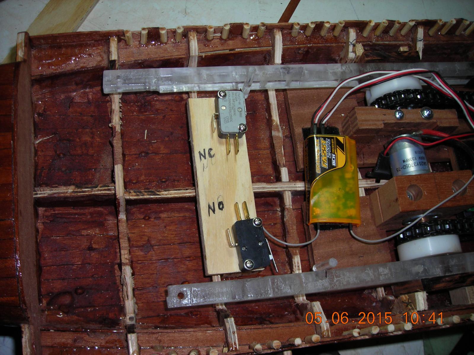
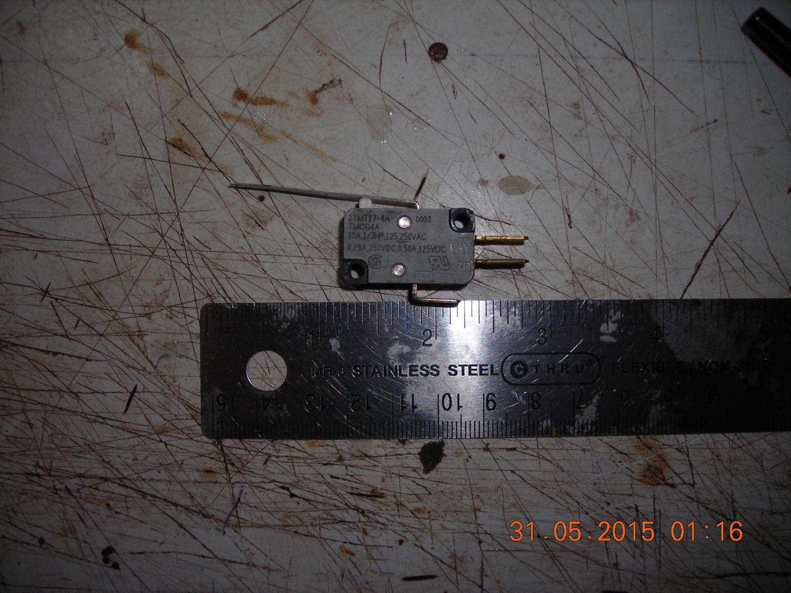
The pictures in this post show the platform and micro switches in the locations I will use them in. On the quicker oar rack I will have a normally closed switch that will become an open circuit once the pin reaches the switch and trips it, thereby stopping the rack motion. The other oar rack has a normally open micro switch that the rack pin will trip making it a closed circuit that will power up the stopped rack to allow it to continue on, but unlike the other switch the duration of this one will be activated longer to ensure continued operation of the fast rack past its own tripped switch. Once I have it all wired and operational I will post a video.

- BenF89, captainbob, Omega1234 and 2 others
-
 5
5
-
This is what I propose to do with the micro switches, the slightly faster rack will trip the normally closed switch first breaking the contact and stopping the rack until the slightly slower rack catches up then it will trip the normally open switch to closed and power up the faster rack to move past it's tripped micro switch. I will have the faster rack set up to be slightly tripped and then slower rack switch will be tripped longer to allow the fast rack to move past the first switch.
- mtaylor, Omega1234 and qwerty2008
-
3
-
-
-
-
The ends of the racks have a flat 90% surface about 3/4 of an inch long, on the one rack I can set it up so it will just trigger the switch to open the circuit to stop that rack then the other rack will hit it's switch at a parallel part of the rowing stroke, that will power the first rack until it's clear from the switch that broke the circuit. For the receiver switch it will be set up to bypass both switches when I turn on a toggle on the transmitter therefor allowing me to turn and reverse the ship.
-
-
-
What you say makes sense Bedford but the motors are a seventy five to one gear reduction, the steering motor would have to be disengaged from the drive chain and then you would only have one set of oars to steer, it just won't give me the look in operation I'm after, plus what you describe would take a better machinist than me, this could become a little too involved. What I am thinking is a micro switch on both rack ends when the first rack contacts it then stops because you've broken the "normally closed contacts then when the other rack catches up and hits it's micro switch and provides power to the other rack while still carrying on it's path. It can be wired to balance the oars that will be next.
-
-
-
Thinking about the boatman on the river Styx I can use three cams to operate the oar or one cam with springs and one "turntable" for steering. That means I will have to make Charon first and build the boat to fit him. Give me something to think about because the Bireme kept me thinking when I started into the mechanics and I do enjoy puzzles like this.
-
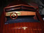
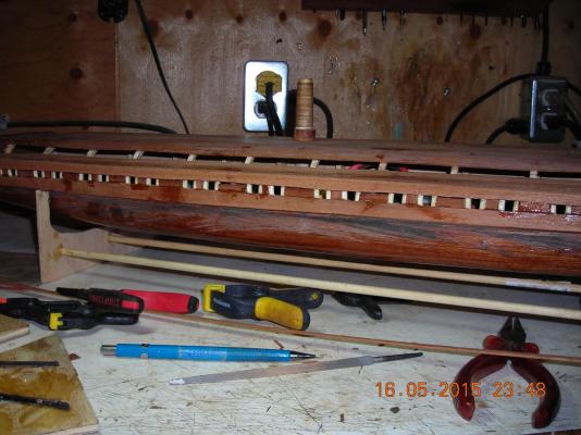
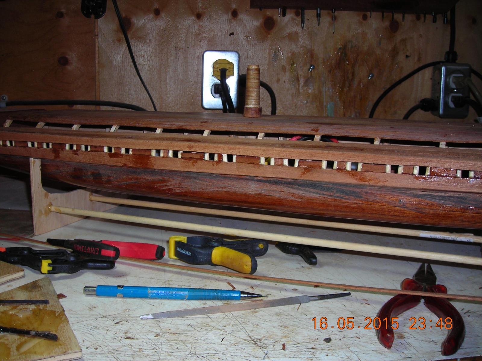
Finishing the tholes I still have to trim them down so the deck will fit properly. I'm just cutting and fitting the planks for a bit of extra strength and improve the look. The piece I made for the mast to slide into doesn't look right and I need a means of securing the deck, so does anyone have any suggestions?

-
-
Love that video that is so cool! For them to build that ship is quite something, great job but looks pretty awkward for the rowers.
-
Very interesting Steven, was one ever built?
-
-


Greek Bireme by bensid54 - FINISHED - RADIO
in - Subjects built Up to and including 1500 AD
Posted
Second set of sea trials, I'm getting better at running it.
https://youtu.be/X7qDxvmfOT0