

bensid54
-
Posts
531 -
Joined
-
Last visited
Content Type
Profiles
Forums
Gallery
Events
Posts posted by bensid54
-
-
Louie, do you know what they did with the mast and sail when using oar power during battle? I've watched videos of the Trireme they built in Greece and when under way with oars they had the sails furled tight. I think that furled sails may be correct because I'm sure they put a lot of time and effort into research before they took on such a huge project and if that was how they set it up I'm sure that must be right.
- avsjerome2003 and Omega1234
-
 2
2
-
-
-
Wow! Lots of interesting information, thanks for all your research avsjerome2003. I'm learning more about this ship as I go along, one thing I'm curious about is how was the sail positioned when underway using the oars? The sail would cause huge wind resistance unless it was taken out of the equation.
-
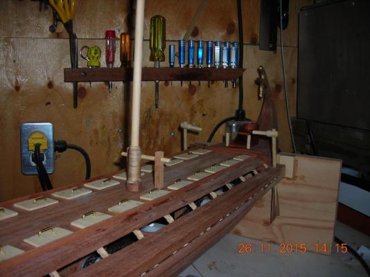
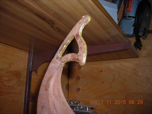
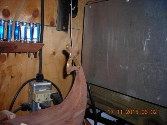
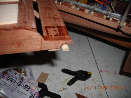
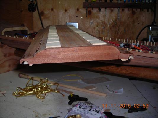
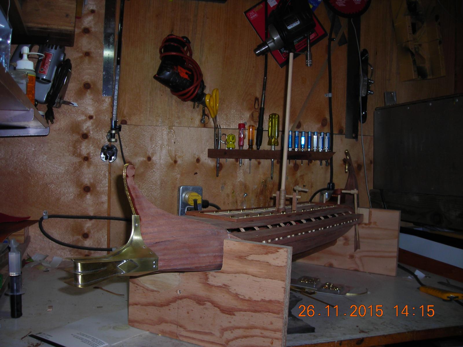
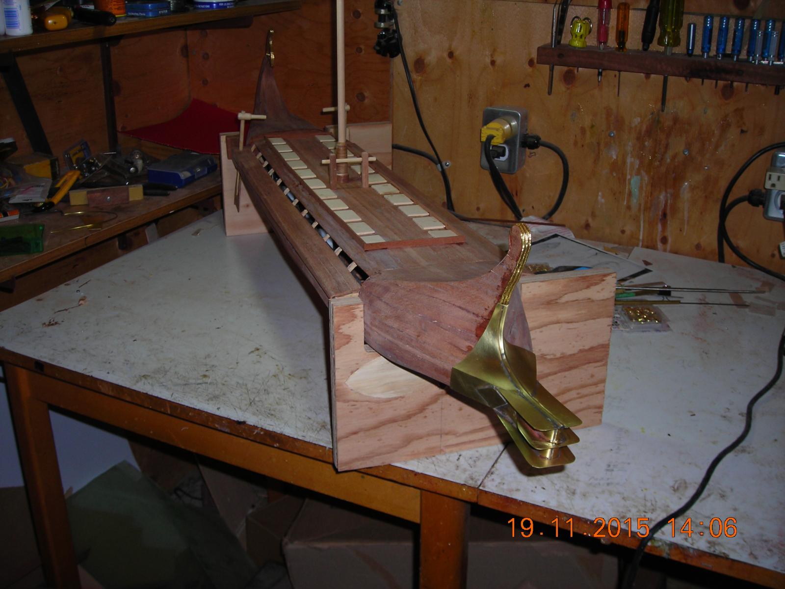
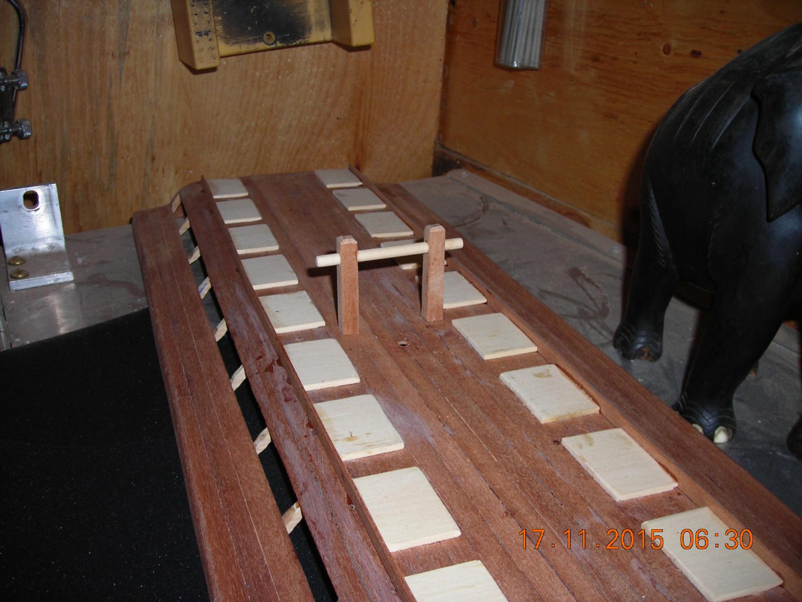
Broke apart the Captains chair and made it straighter then glued it into position. The two posts by the chair will be railing supports, the railing will run from both sides of the chair to port and starboard then forward just past the rudders. Almost finished the stern detail and took a couple more shots to show how it's all shaping up.


- avsjerome2003, BenF89, ianmajor and 5 others
-
8
-
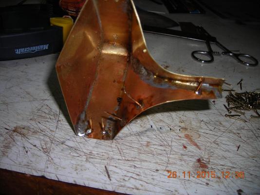
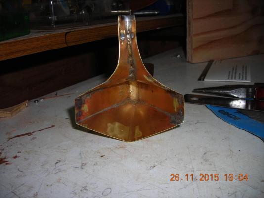
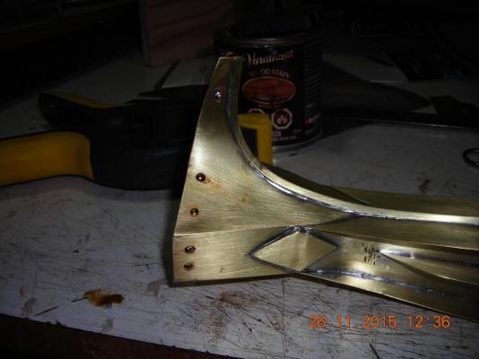
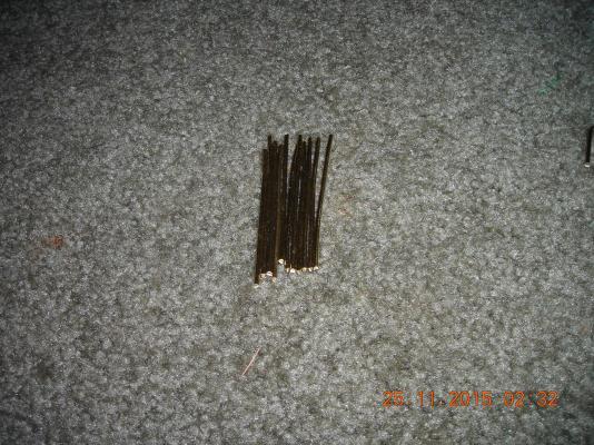
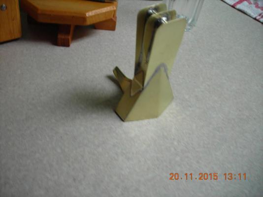
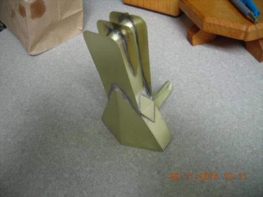
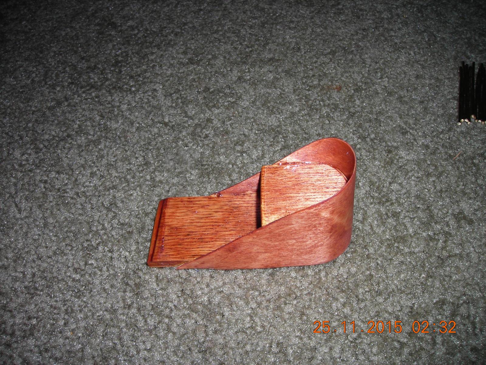
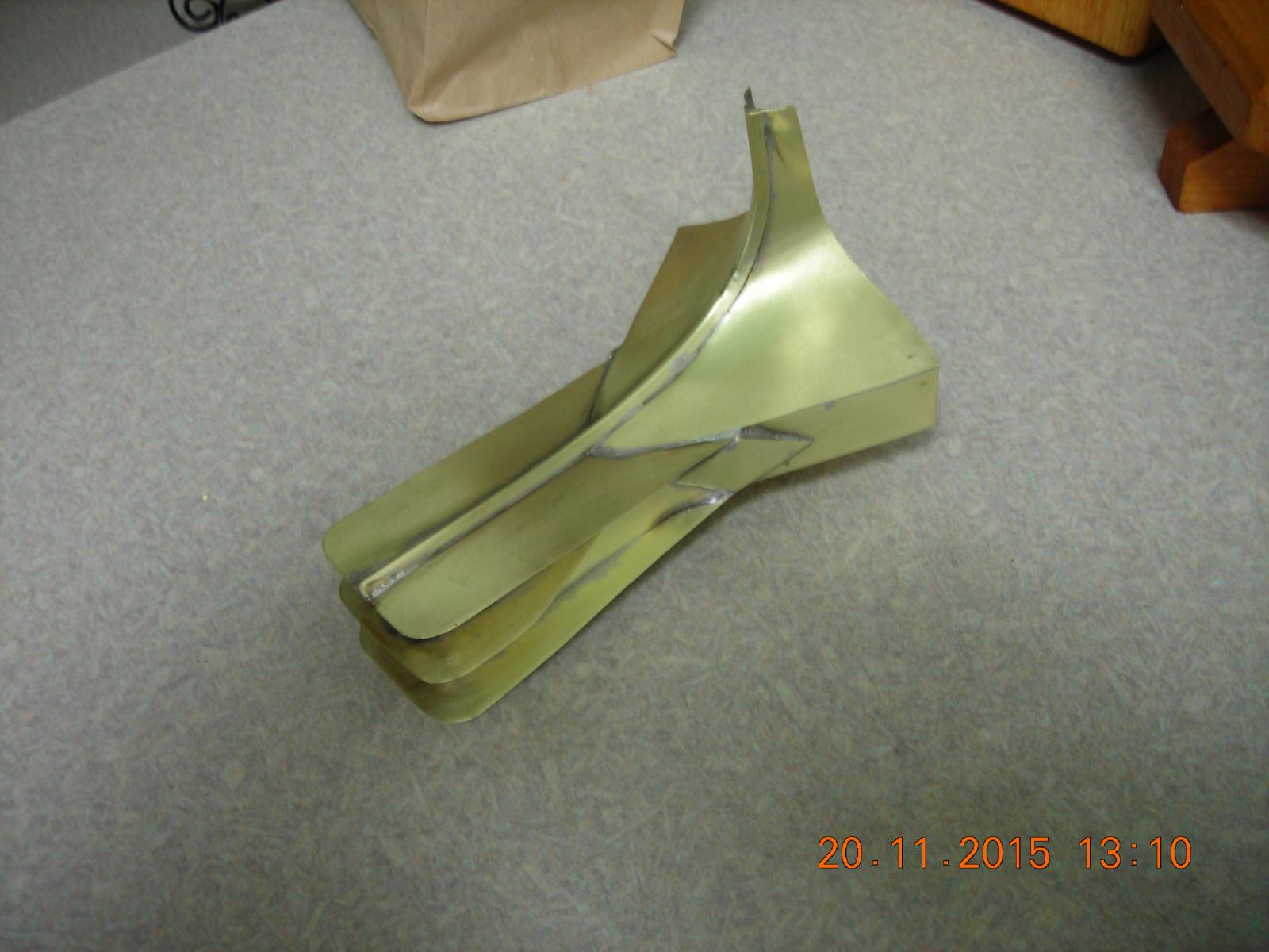
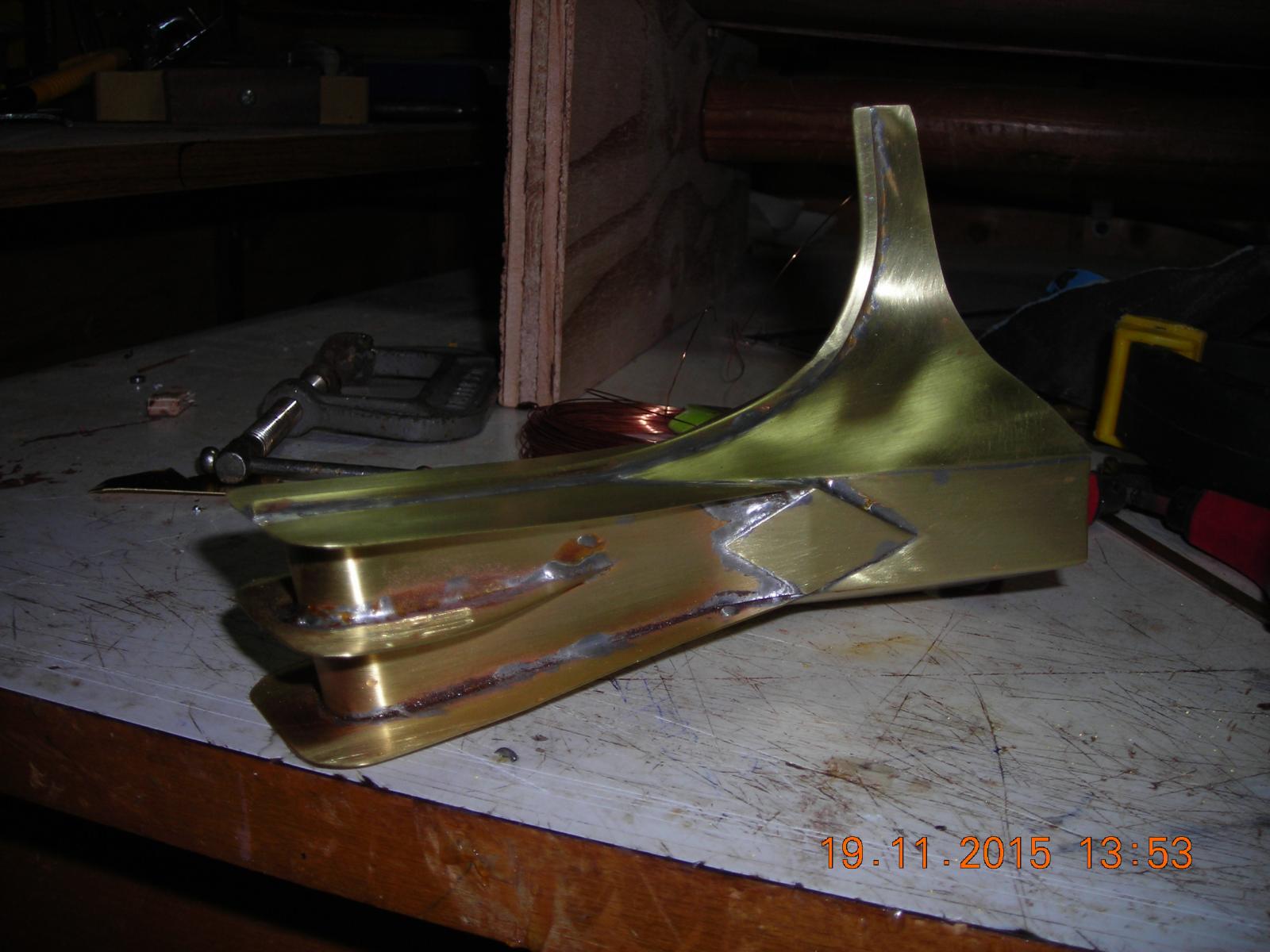
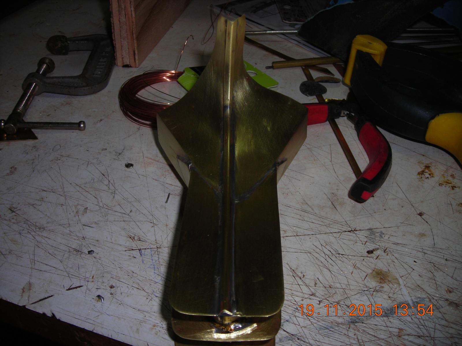
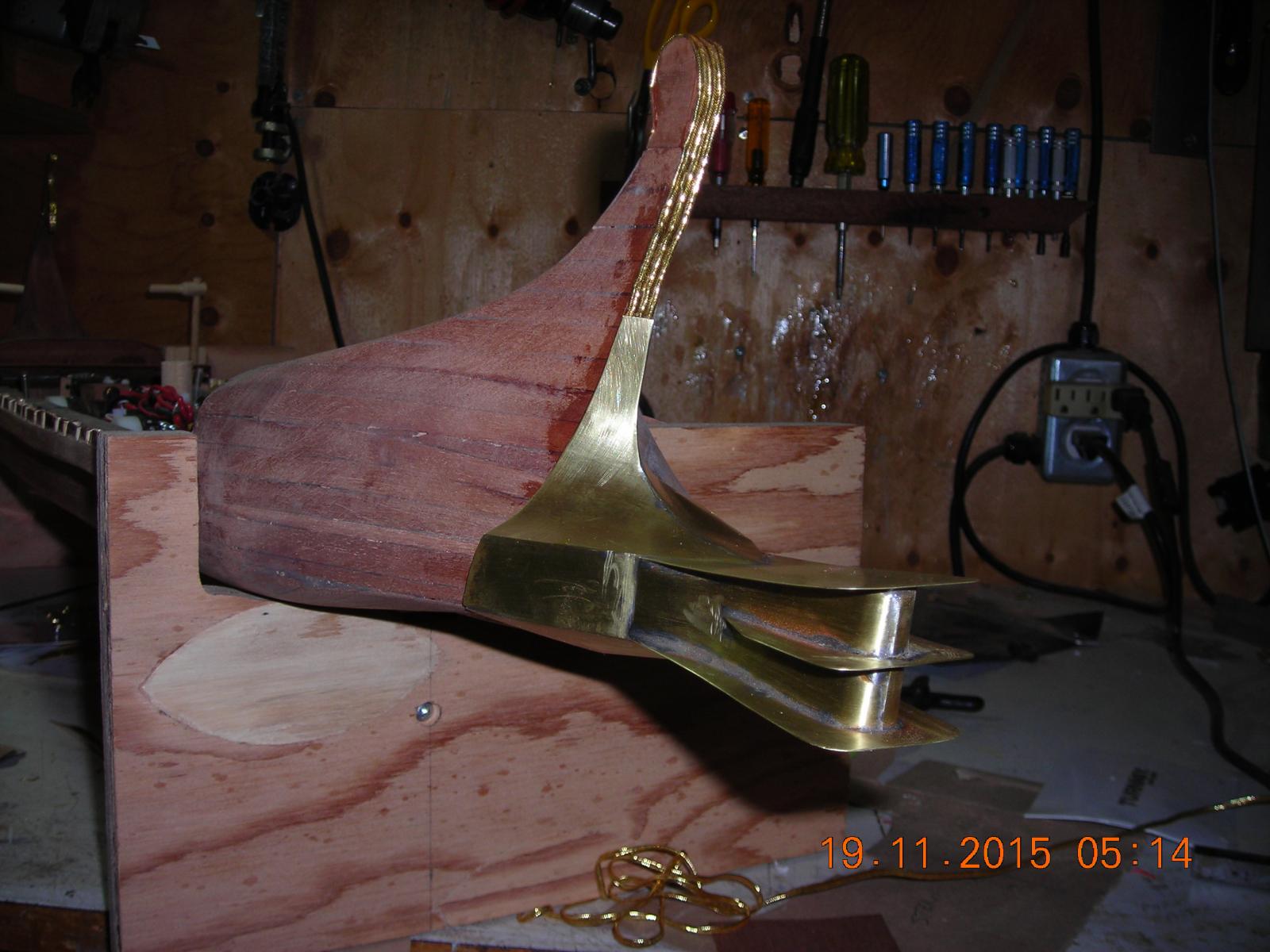
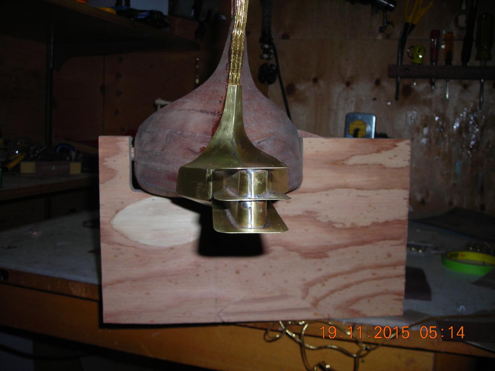
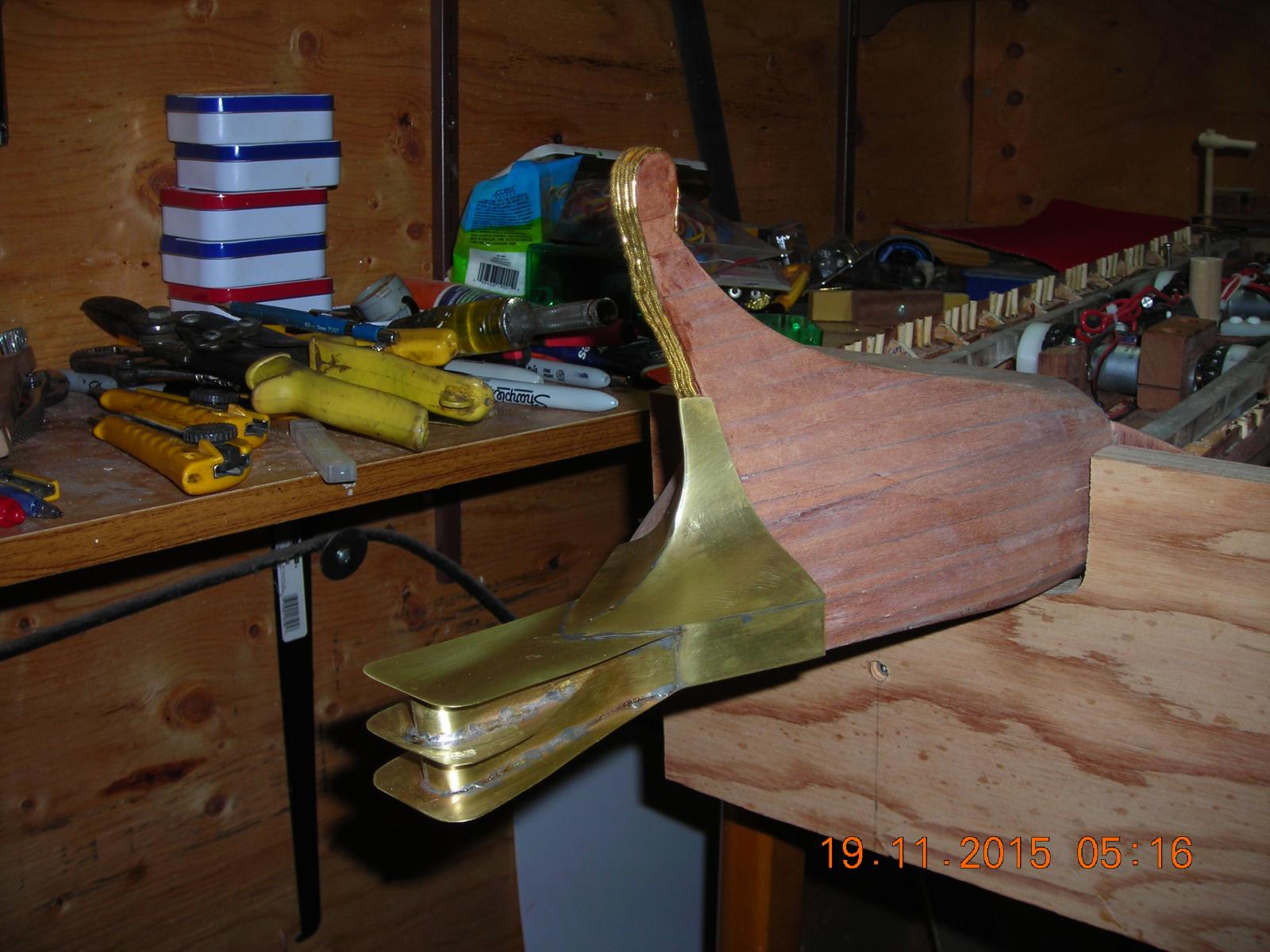
Put the dummy spikes in yesterday. Measured the location the spikes would be located, marked them and drilled them with a machinist centering drill bit because a normal bit would be too flimsy and leave tracks over the areas it would stray. I had some brass covered nails that were just the right size so I soldered them in place, cut them to size, and made them flush inside with a Dremil drum sander. What you see is all the detail I will put in the ram.

-
Thanks Bob, more to come!
-
-
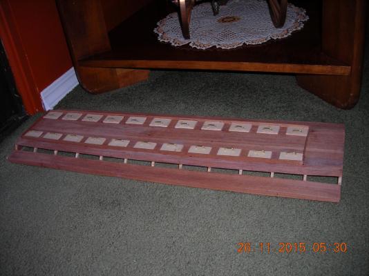
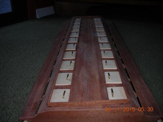
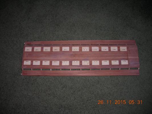
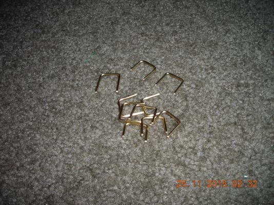
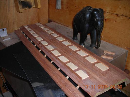
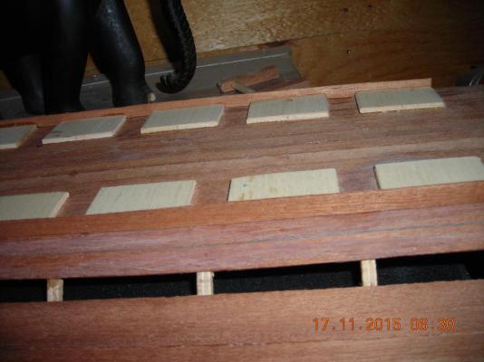
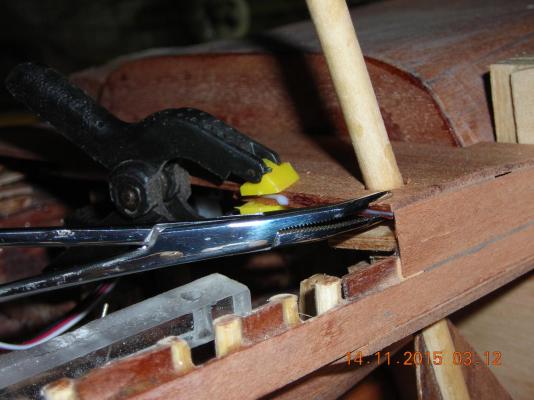
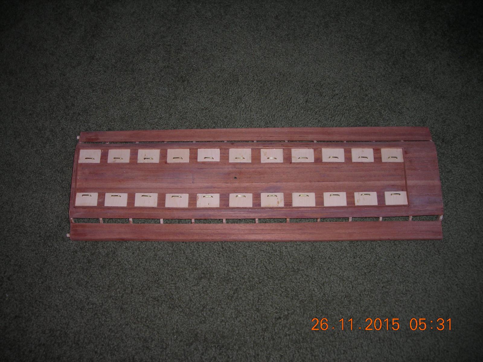
Hatch handles complete and installed! I drilled holes in the hatches using a jig I made up so they can be uniform.

- avsjerome2003, mtaylor, captainbob and 1 other
-
4
-
-
-
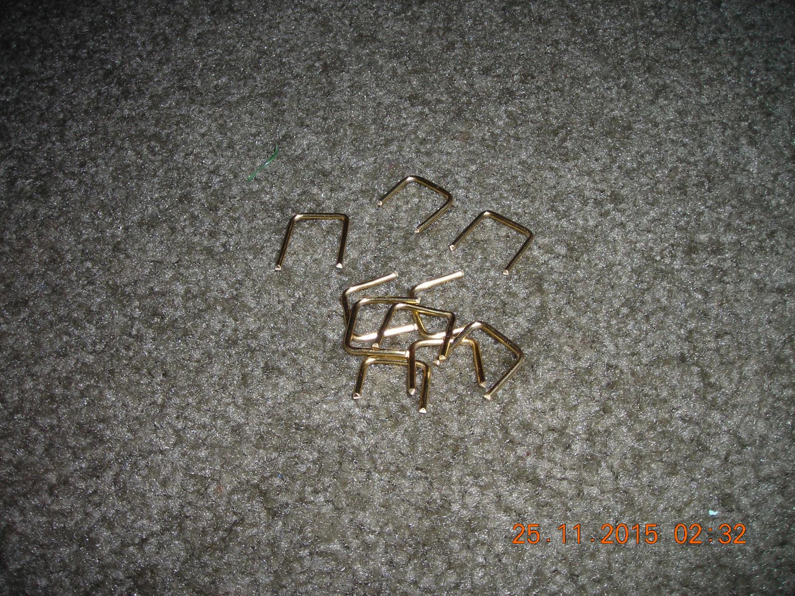
Starting to make the hatch handles, using 3/32 brass wire and bending them around a jig. I will have to make another jig for drilling the holes in the hatches to make sure they will all look the same.
- mtaylor, BenF89, captainbob and 1 other
-
4
-
Thanks avsjerome2003 ! Your picture is going to come in handy for the placement of the dummy spikes I will put in. I'm sure they weren't all exactly the same so this one could be even closer to looks than one that may still be found. I'm pleased with the amount of input I've had from those on this site it has been a real blessing to have this kind of guidance.
- avsjerome2003, Omega1234 and mtaylor
-
3
-
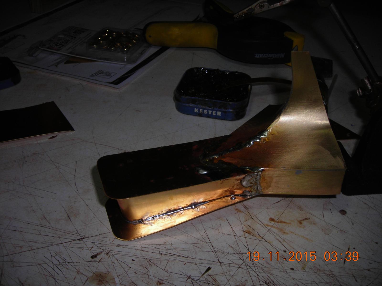
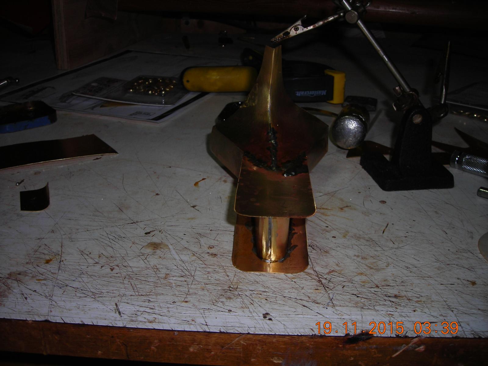
I agree Bob! I glued two pieces of brass together with silicon and after twelve hours it seemed to hold well. I'm thinking that the soldering paste may be a problem when it comes to the silicon sticking so what I'll do is use electrical contact cleaner to get all residue off then use your idea to rough up the surface. I think that will be my best bet.
- captainbob, Omega1234 and mtaylor
-
3
-
Thanks for the link I found another one on the same page which is really cool. And of course I can't paste it on this website, sorry.
- mtaylor, Omega1234 and avsjerome2003
-
3
-
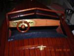
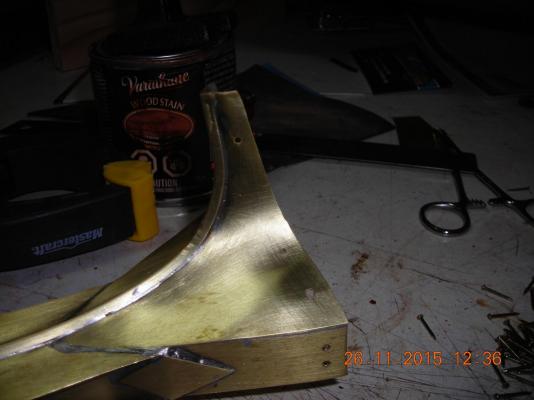
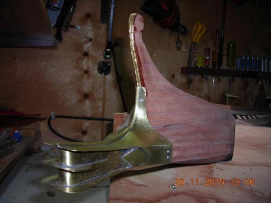
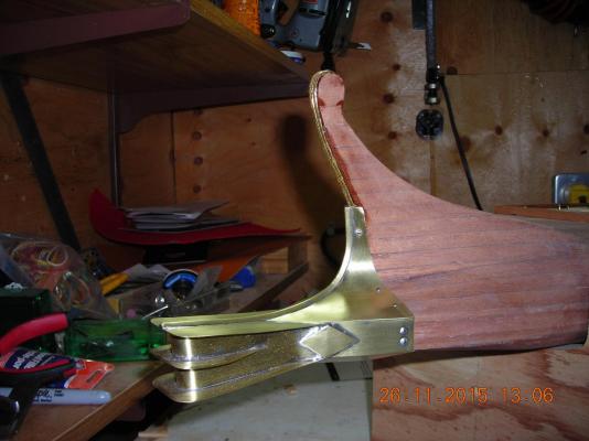
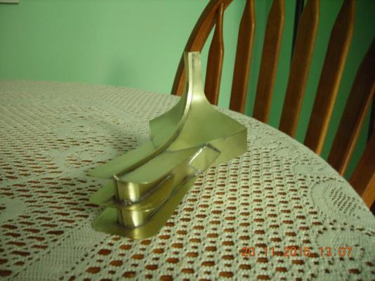
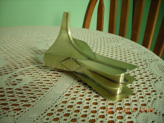
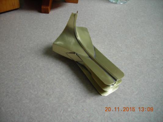
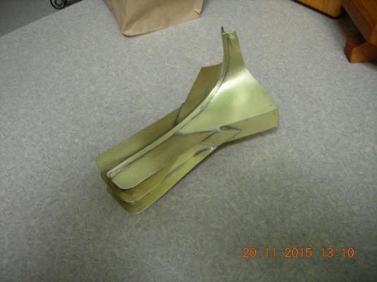
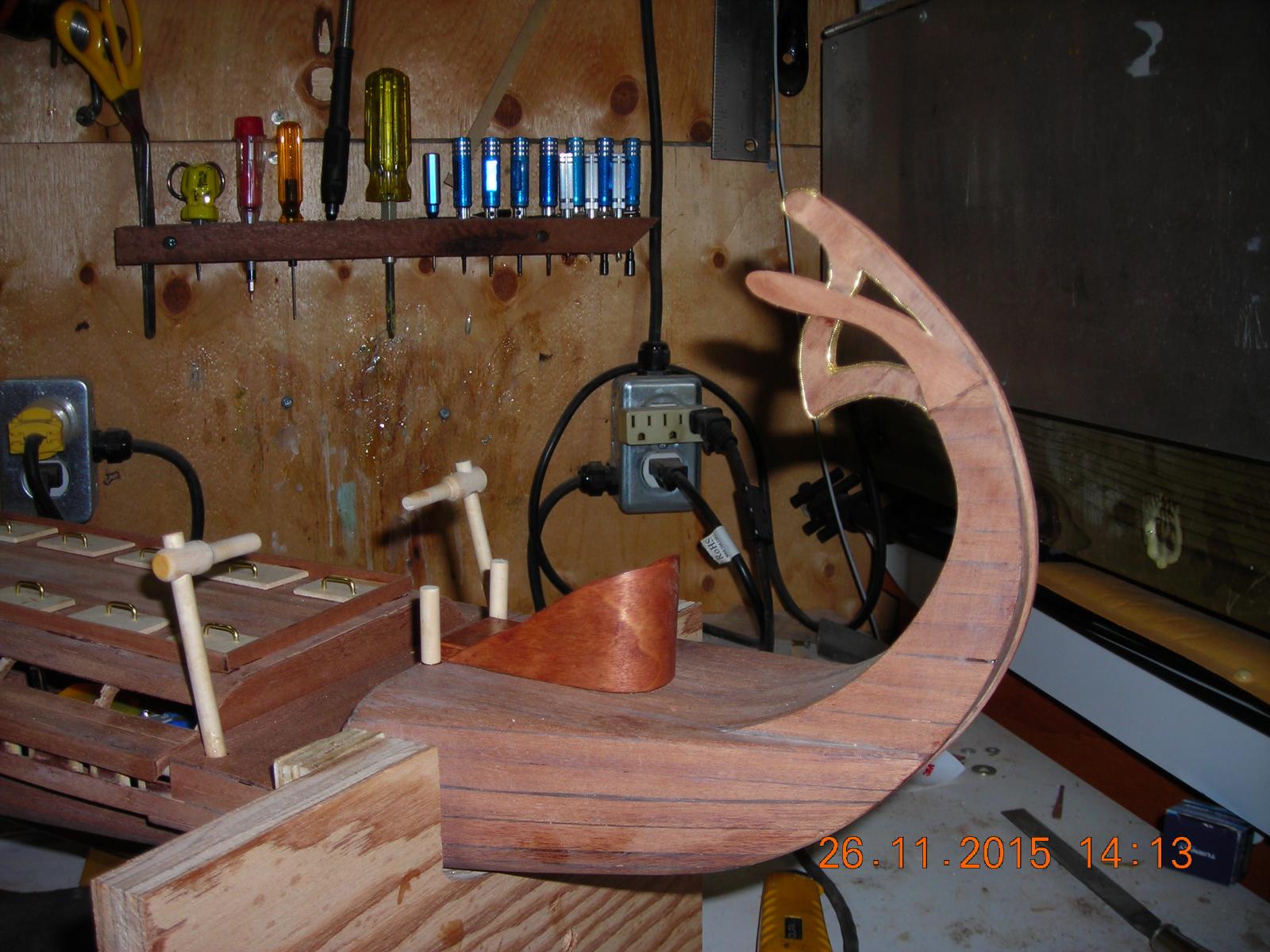
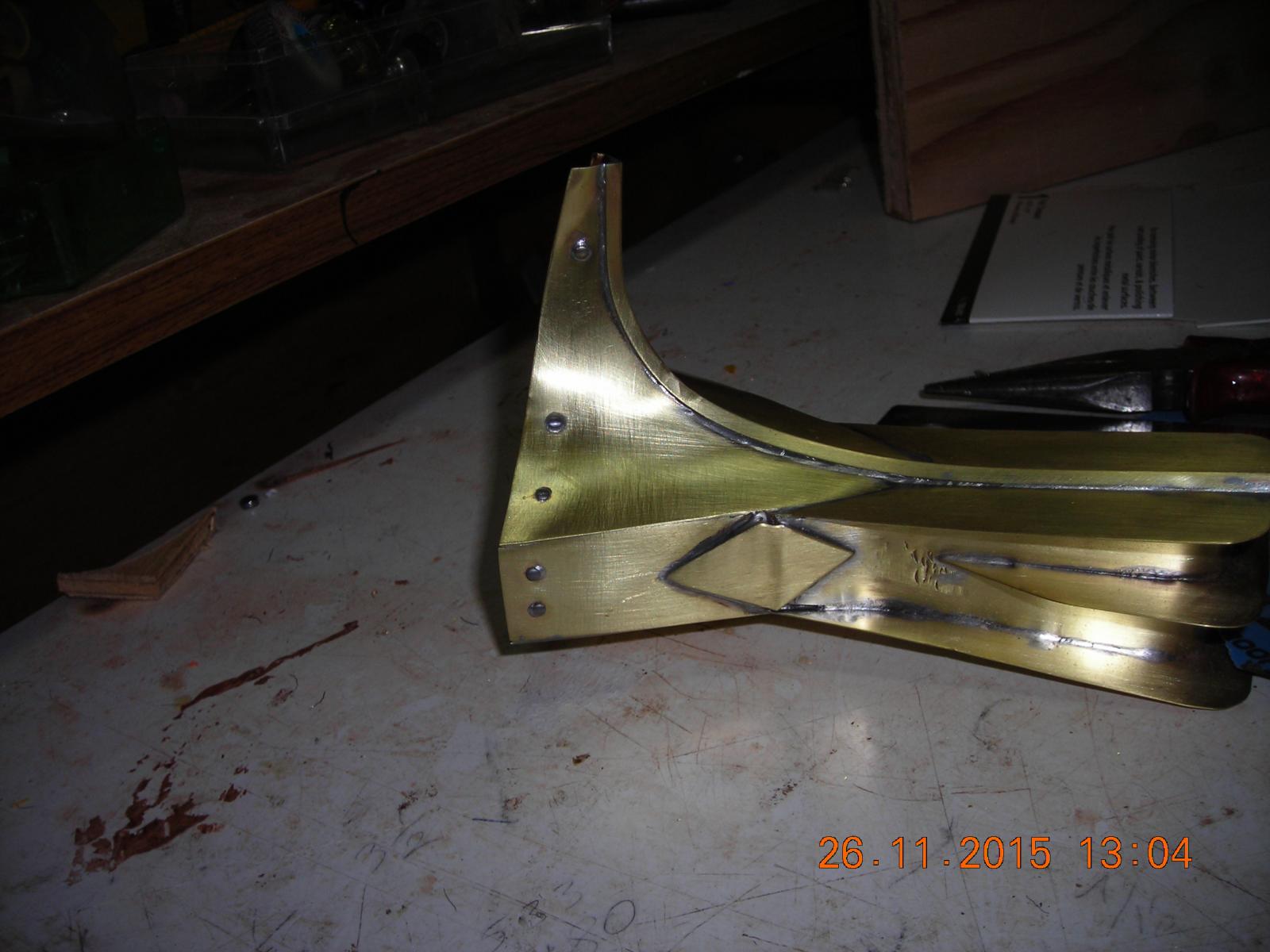
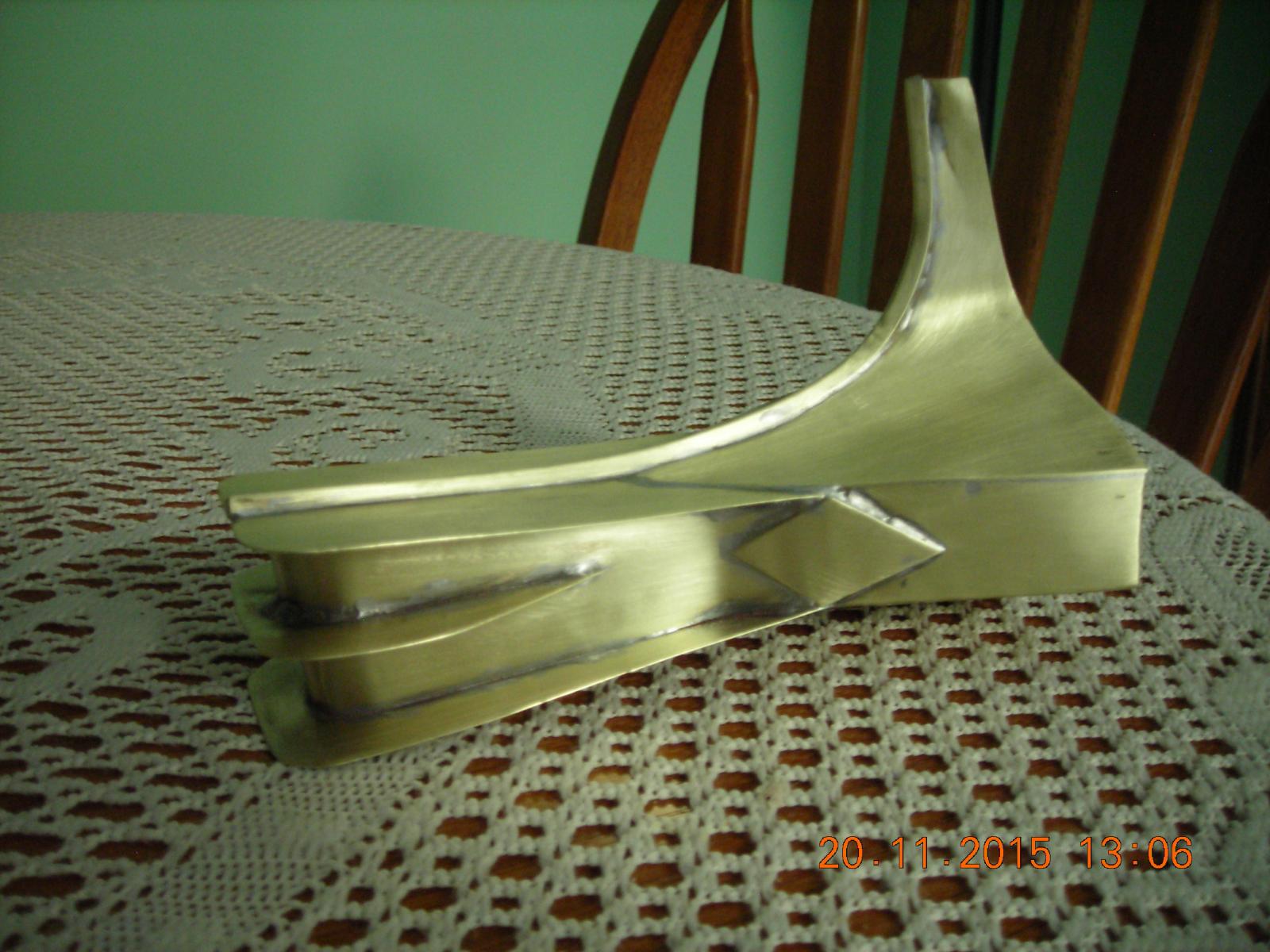
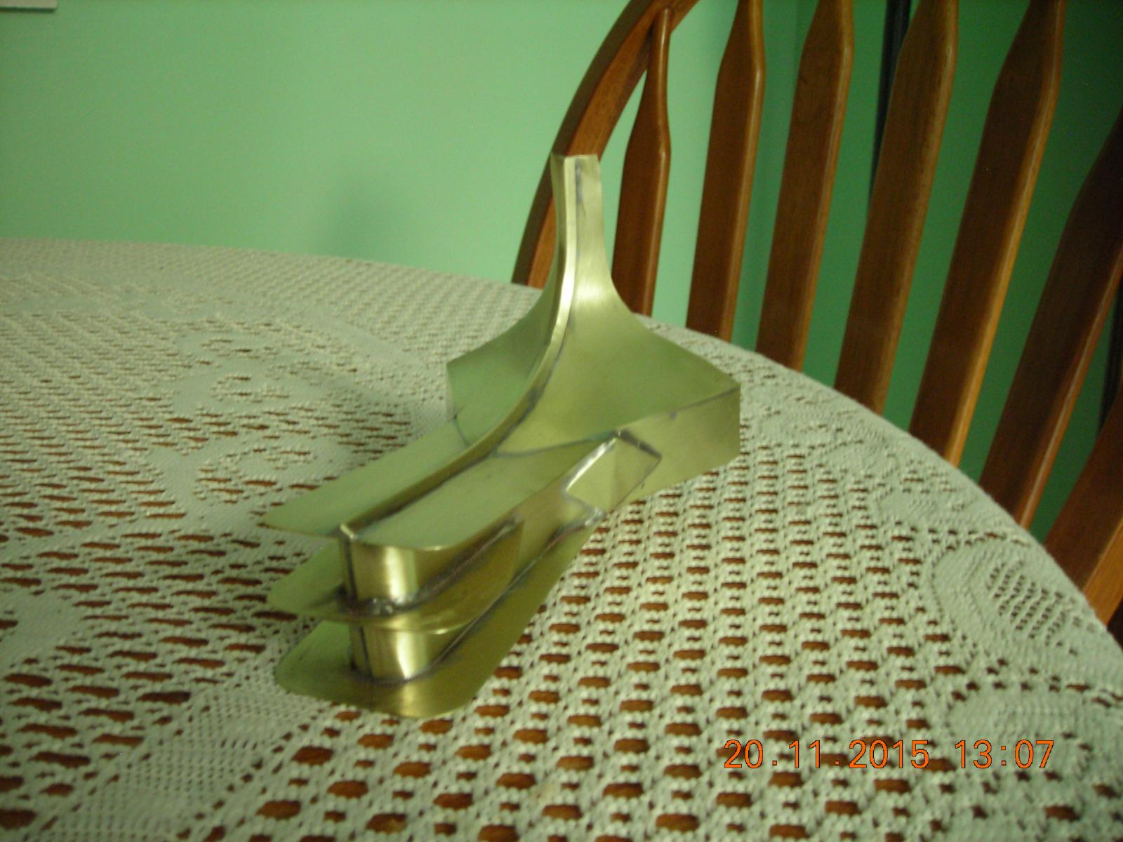
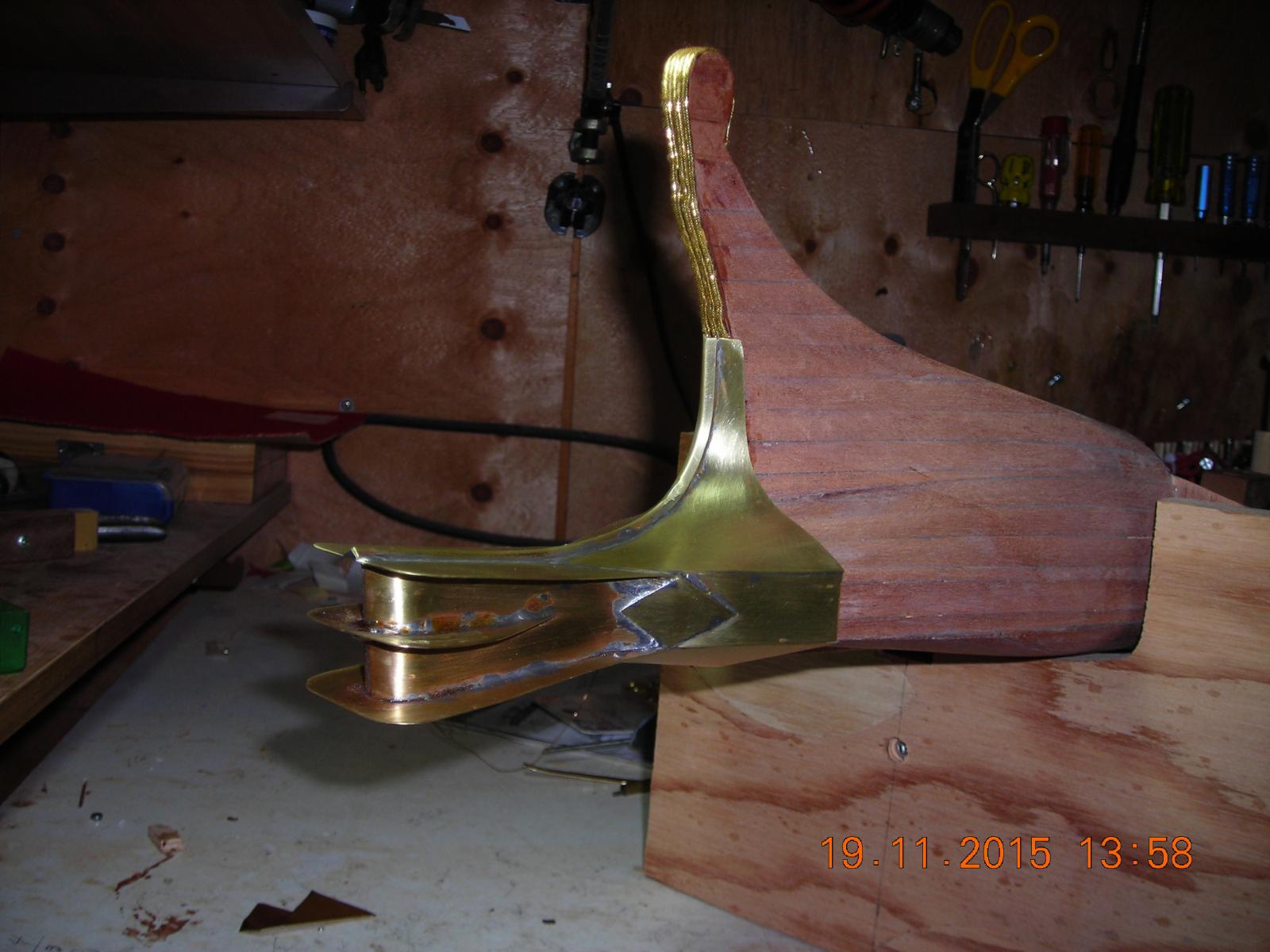
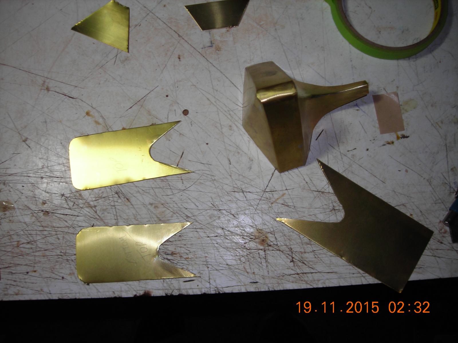
Thanks Patrick! I wasn't satisfied with how it looked and thought about painting it so I checked out this Liquid Leaf on line which was recommended by another ship model builder but it would look painted and I want a real metal look to it. Three Dremil wire wheels, one rough scotch pad, one not so rough scotch pad, one leather buffing wheel, two fabric buffing wheels, polishing compound and two and a half hours labour to get what you see in the pictures. I'm debating whether I should use silicon to glue it to the hull rather than using nails and putting holes in the hull, because nail holes could be a source of water ingress. I will do a test gluing on scrap brass plate to see if it will stick to the brass because if it does that is the route I'll go. Any suggestions as to another type of glue that may be more effective.

-
-
-
-
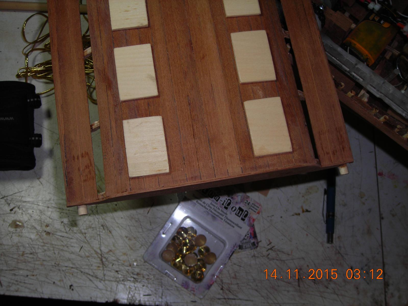
Now for finishing the deck and details.

- GuntherMT, captainbob, Omega1234 and 1 other
-
4
-
I'll try that, now because he is Supernatural it could be the boat propels itself and he just acts as a rudder man. That would mean hiding all means of propulsion under his robes, that would be easy to do if I were to use a water jet.
- EJ_L, mtaylor and thibaultron
-
3
-
-
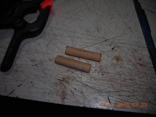
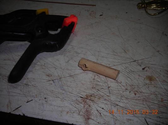
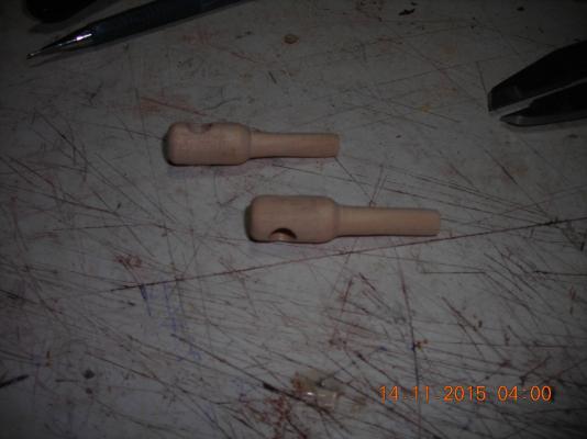
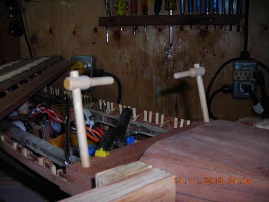
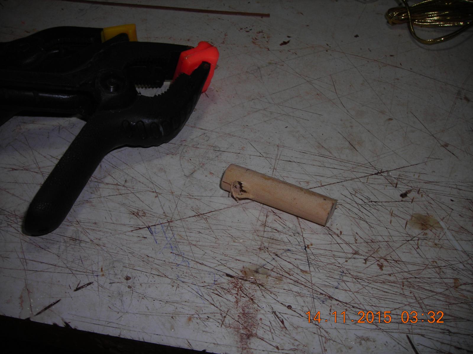
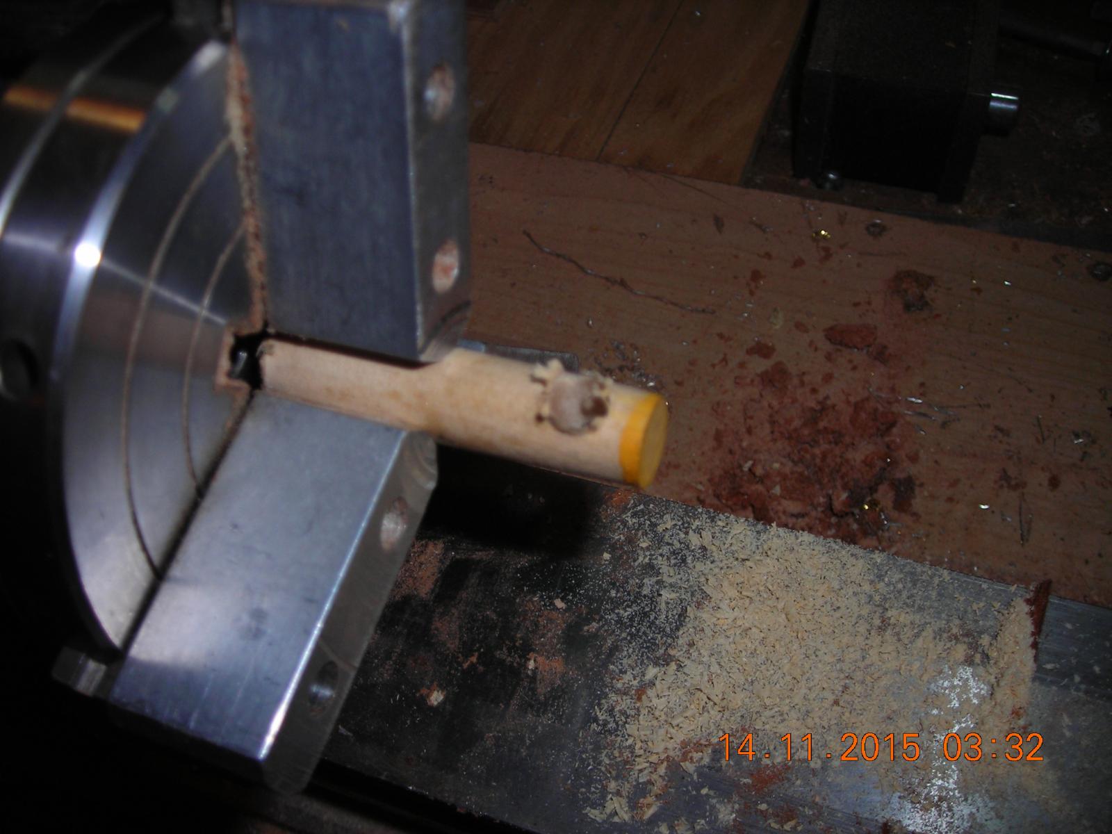
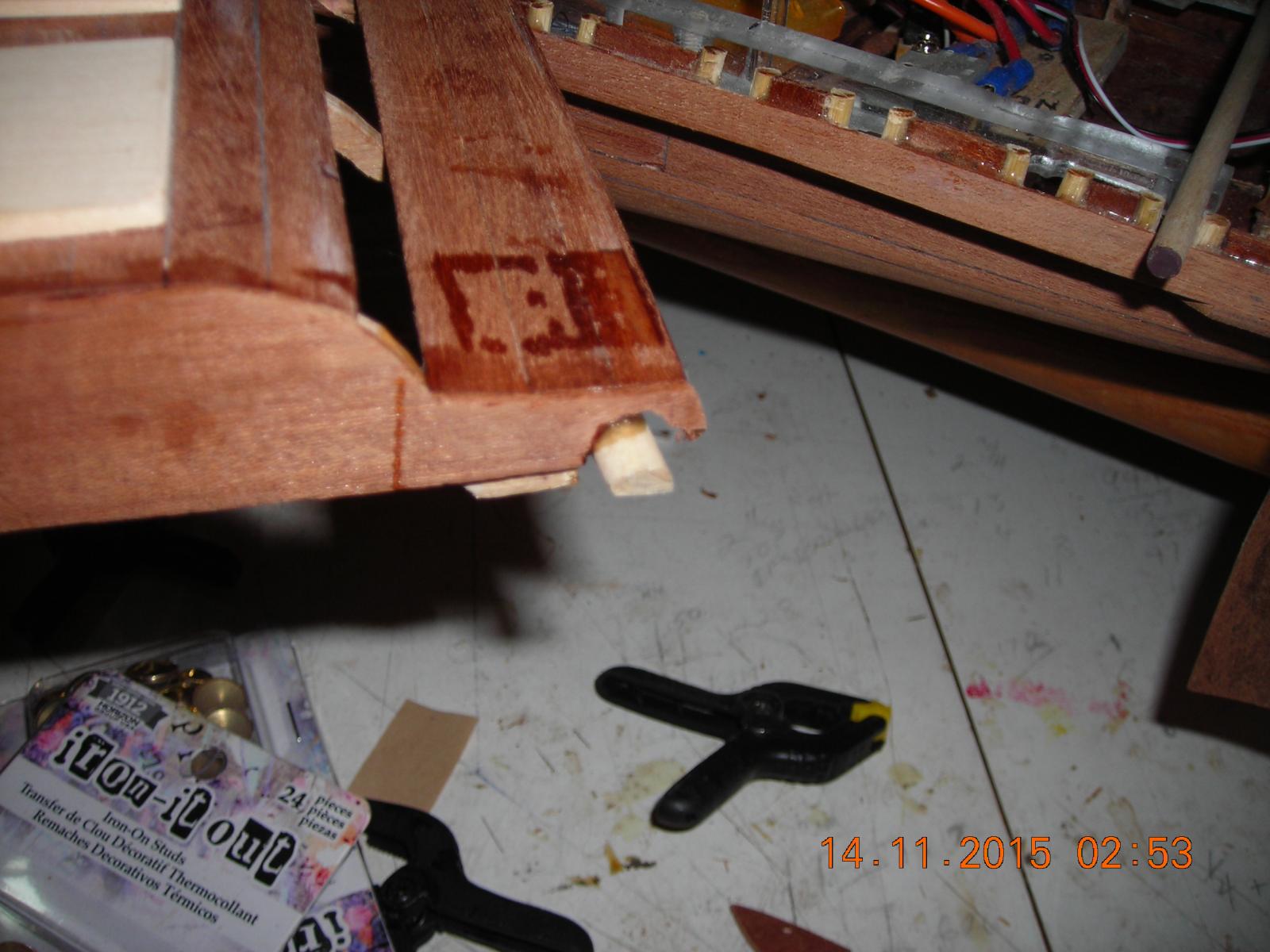
Making the rudder handles now. First I cut some 3/8inch dowel to size then drill them with a 1/4inch drill bit in the lathe, the reason I use the lathe for drilling is to get the two of them properly centred and even. Turning them is the lathe with my small woodworking tools was a little tougher than I thought but with some careful sanding and shaping they seem to have turned out fine. The final picture is the handles installed but I still intend to use thread to give them the appearance of being bound. The next step will be clear coating the bottom of the hull, painting the cradle and using fluffy Velcro on the cradle to protect the finish on the bottom of the hull, once that is done I will be finishing the upper deck area.

- Omega1234, captainbob, mtaylor and 1 other
-
4
-
Thanks Patrick! In these pictures I added pins to the aft end of the upper deck to slid under the Helms mans deck. At the Port side I had to shim it just a bit to get a good fit because I found a wee bit too much play there. Those that watched my video of the Bireme in the pool likely noticed one of the oars became misaligned during operation, that was due to the deck lifting and allowing the oars to leave their tholes. With the pins added the deck will not lift now and once I have finished the Bireme I will use silicon grease to lube all moving parts, that will help immensely too.

- captainbob, mtaylor, Omega1234 and 1 other
-
4


Greek Bireme by bensid54 - FINISHED - RADIO
in - Subjects built Up to and including 1500 AD
Posted
When sails were furled on the Bireme did someone also climb up and bind them or secured them tight with rope?