mrcc
-
Posts
572 -
Joined
-
Last visited
Content Type
Profiles
Forums
Gallery
Events
Everything posted by mrcc
-
Very poor service indeed... I had some problems with Cornwall Model Boats as well with regards to unanswered emails on a special order of a part. They are both hit and miss.
-
My advice is to keep pestering John at Jotika… He will eventually get back to you but it often takes a while.
-
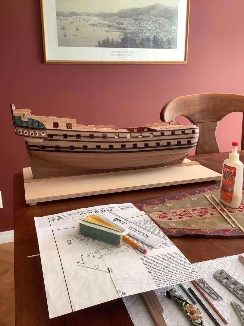
 Just getting the little details done at the current stage of the build, roughly to the Mamoli build order as outlined in their instruction sheets. Tonight I will tackle the deck railings.


-
Hey zappto… so glad you are following my build log. Yes, going to paint the hull. PS I am always referencing your build log and always have my iPad tab open to your build for quick references. Thanks,
-
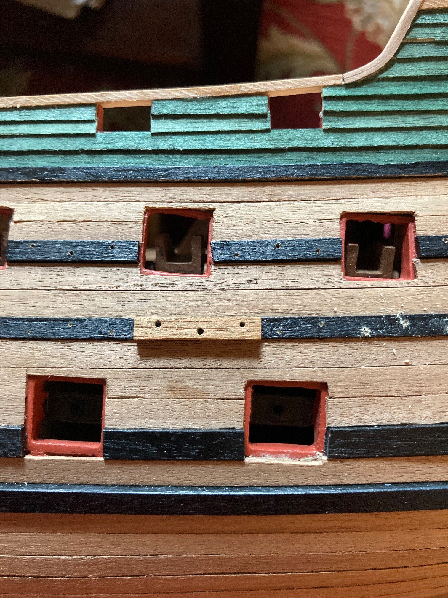
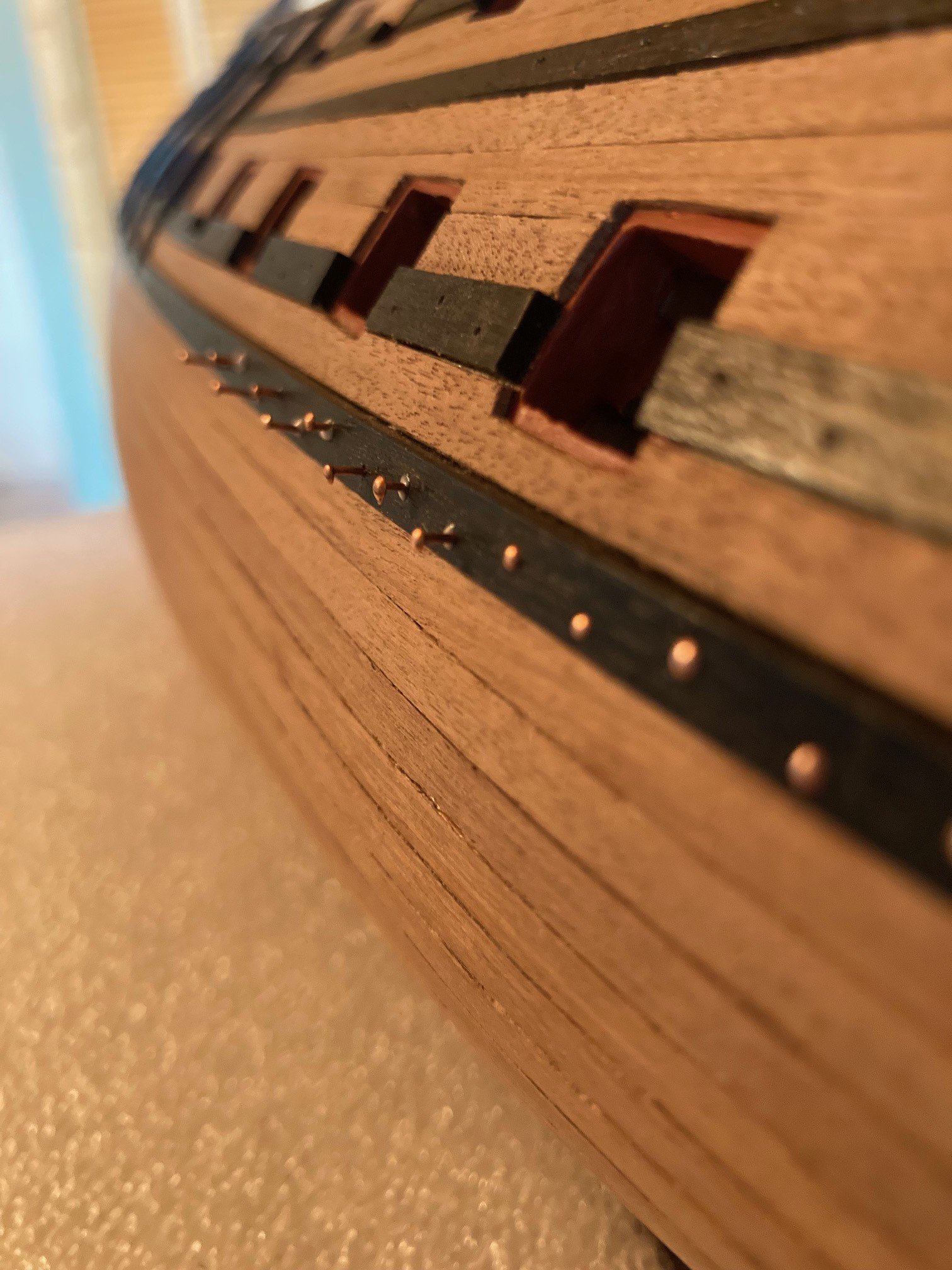
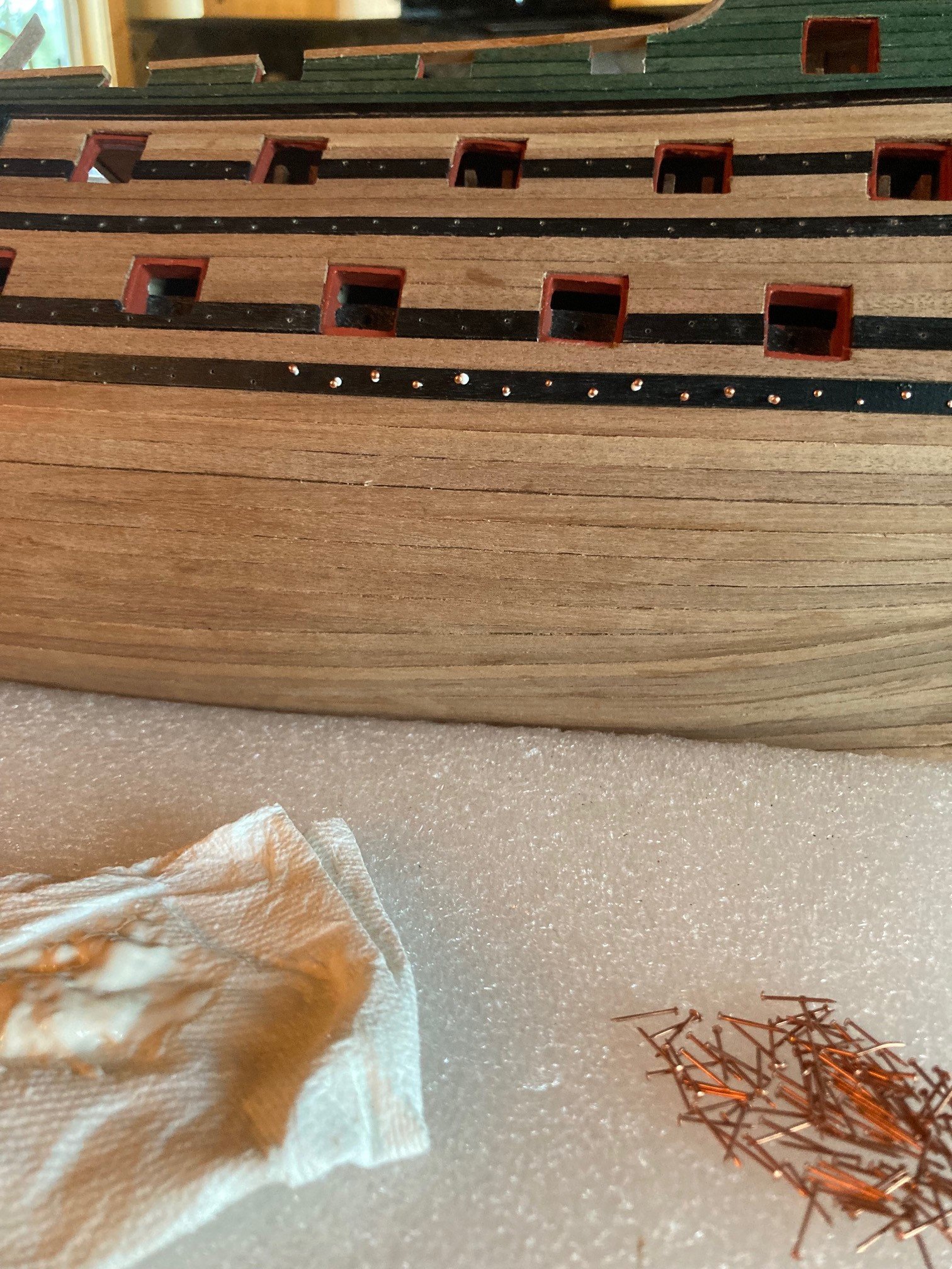
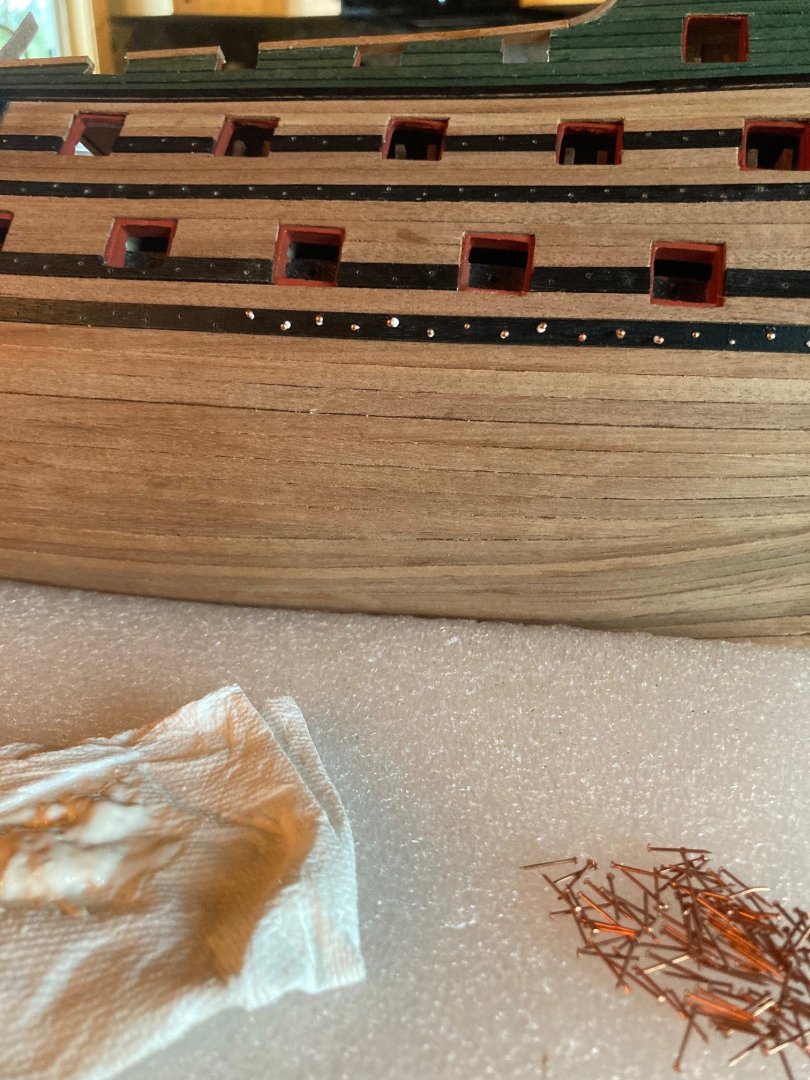
More progress this weekend... Finished nailing the copper nails into the strakes. Created a little template and ran it along the strake with a quick touch with my archimedes pin drill and then came back to fully open the hole for the pin. Quick dab of yellow PVA glue and pushed it in in large sections at a time.


-
Thanks Ronald… The stain I used is about 23-24 years old, used it for a furniture project for my children’s bedroom when they were just babies. Luckily I didn’t throw it out. I opened the can up and stirred it for about 20 seconds and it mixed up perfectly. Perfect stain color for my Friesland!
-
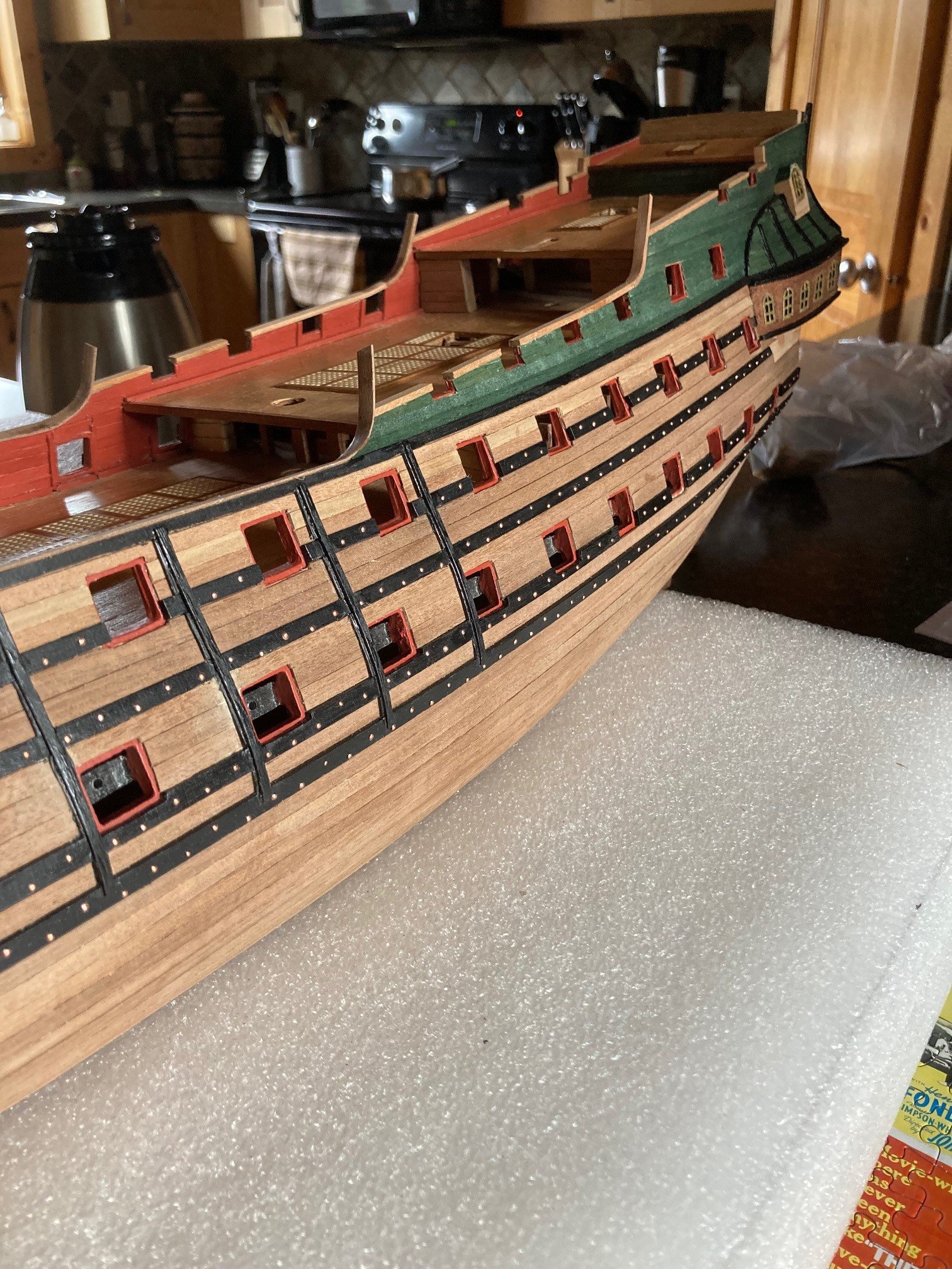
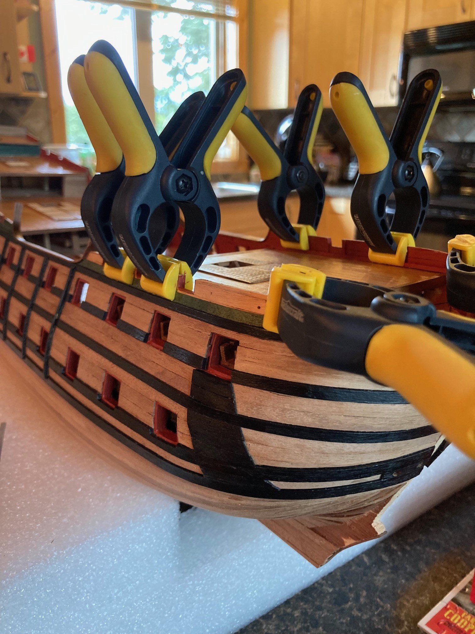
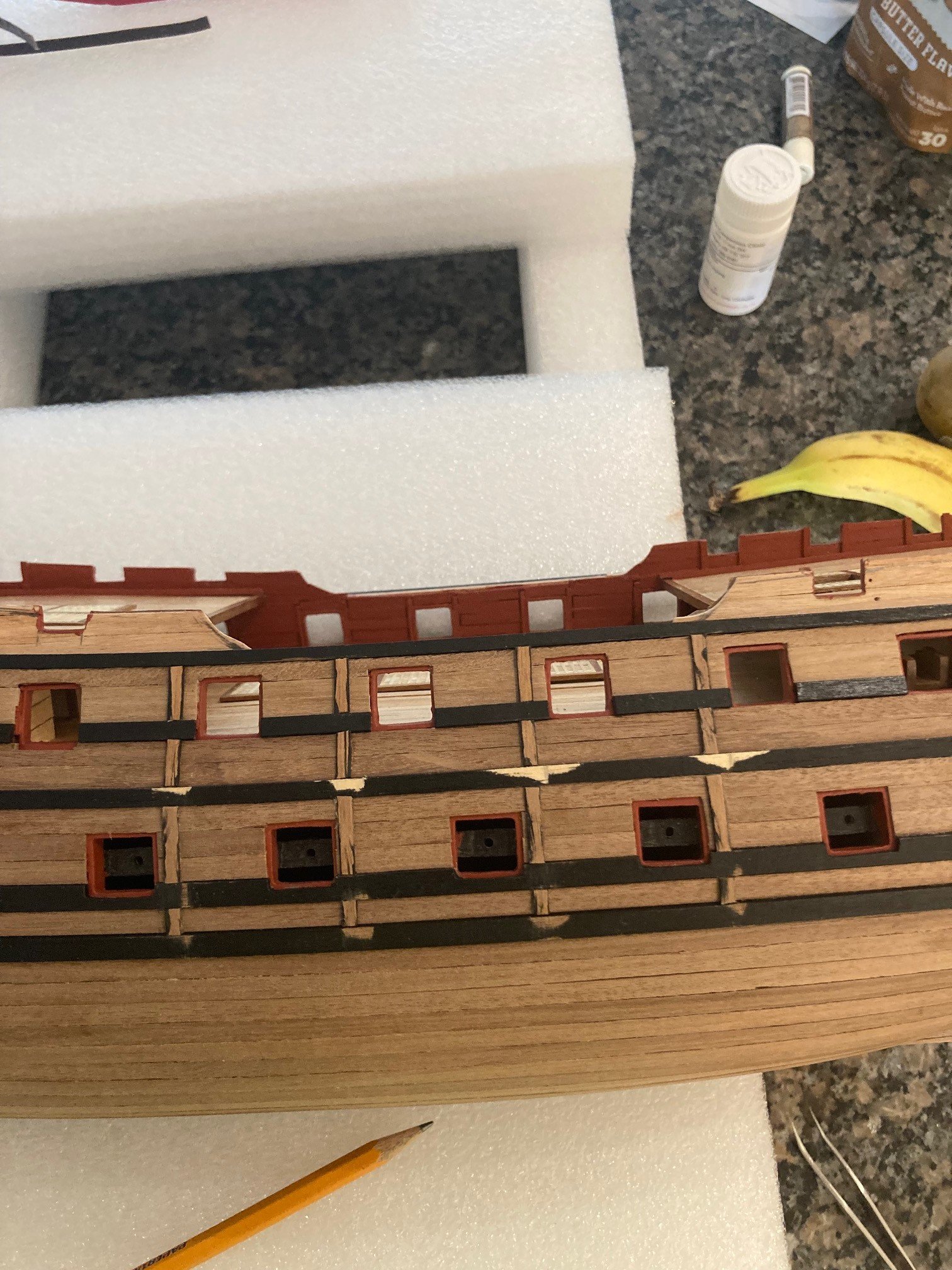
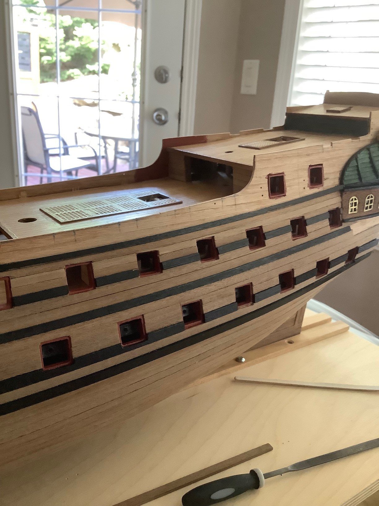
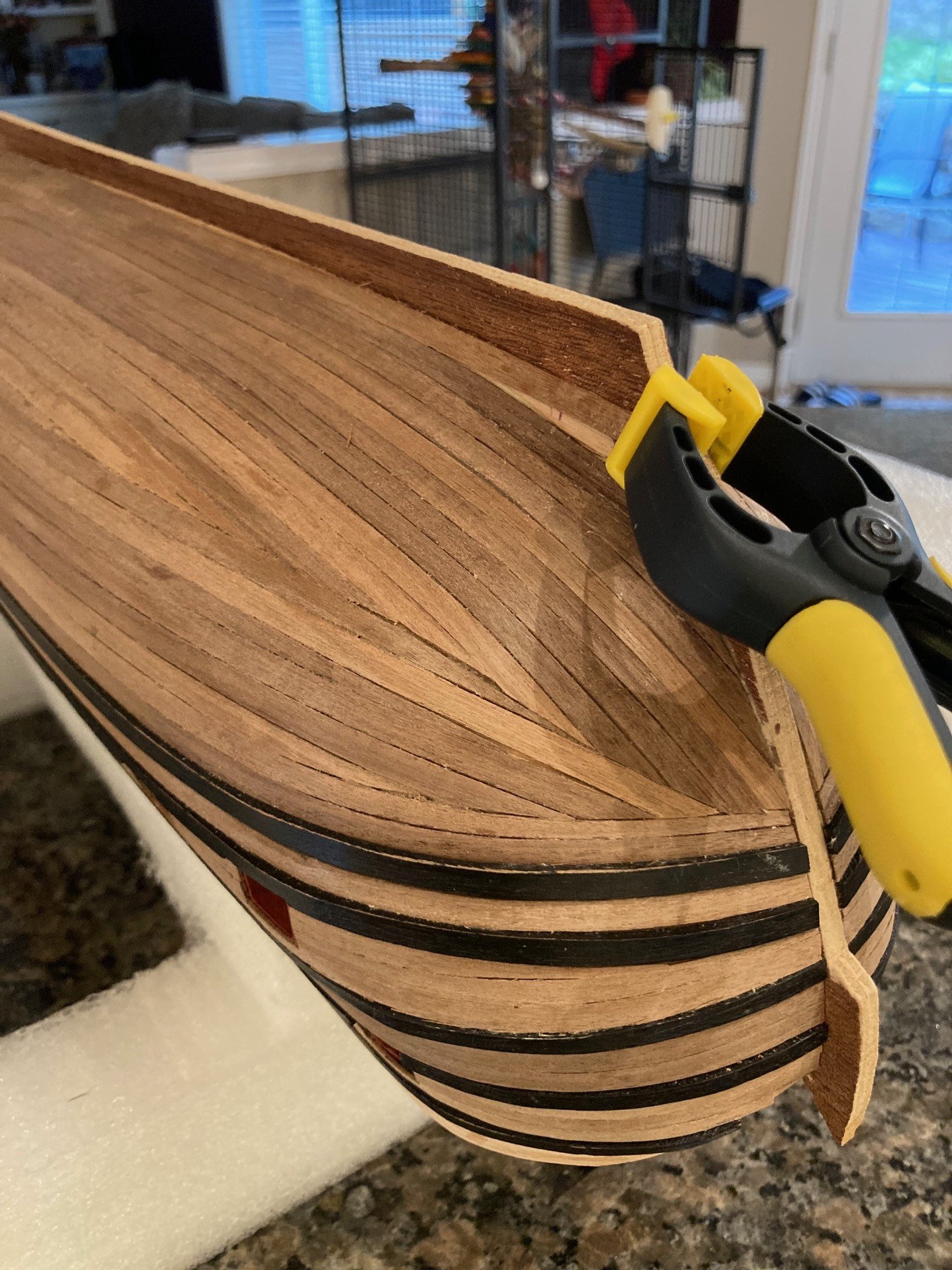
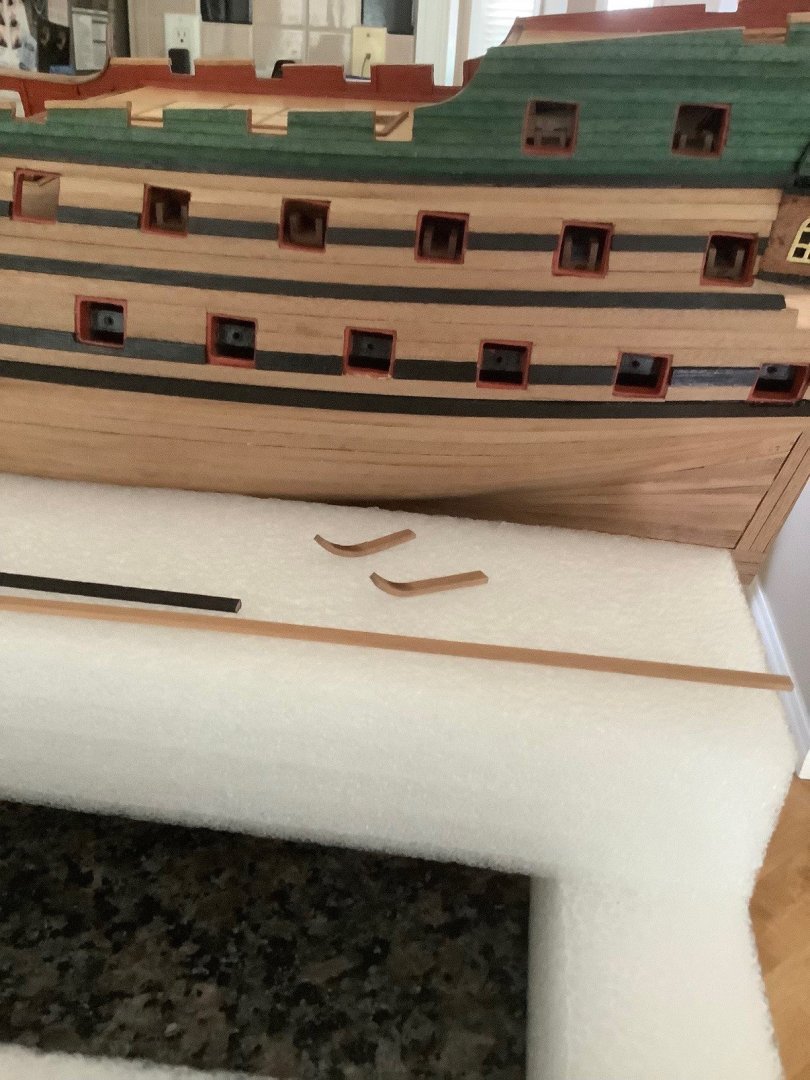
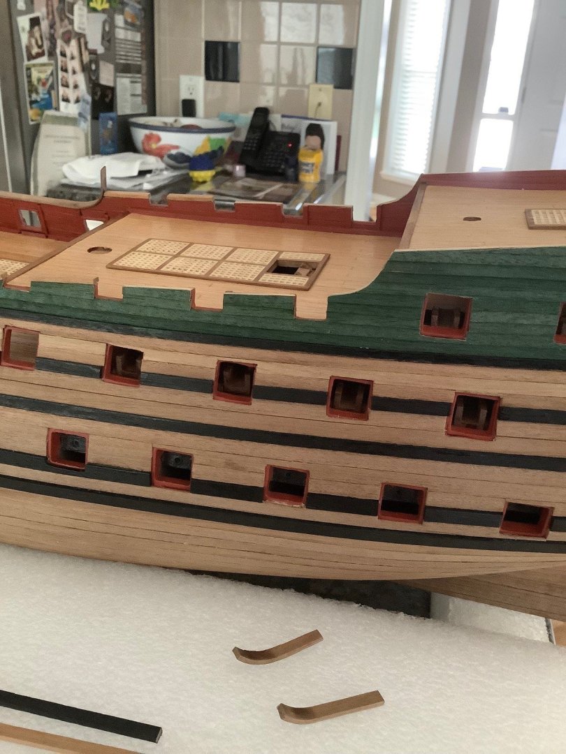
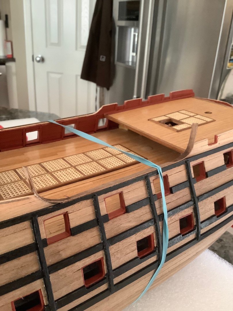
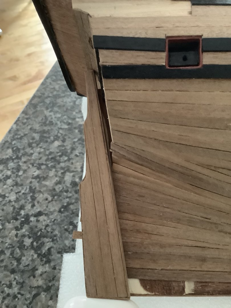
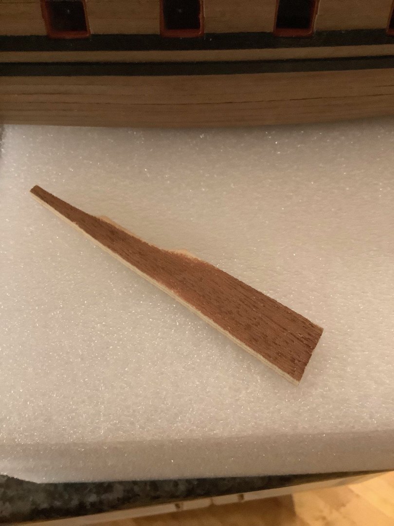
The cap railings are 2x4mm but at the curved profiles, found it absolutely impossible to soak and heat bend the planks. I ended up bending a couple of 1x5mm planks and then once I got the correct curved profile, was able to laminate the two 1x5s to get closer to the rest of the spec'd 2x4mm railing. Sanded them back a bit, sanded a bit of the heat scorch marks and very happy with the results. Thanks to everyone for checking out my build log!


-
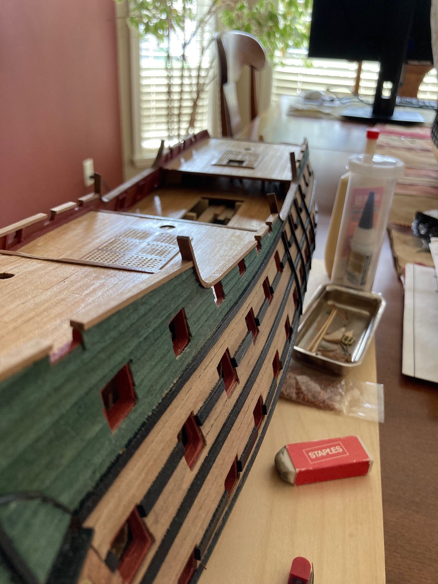
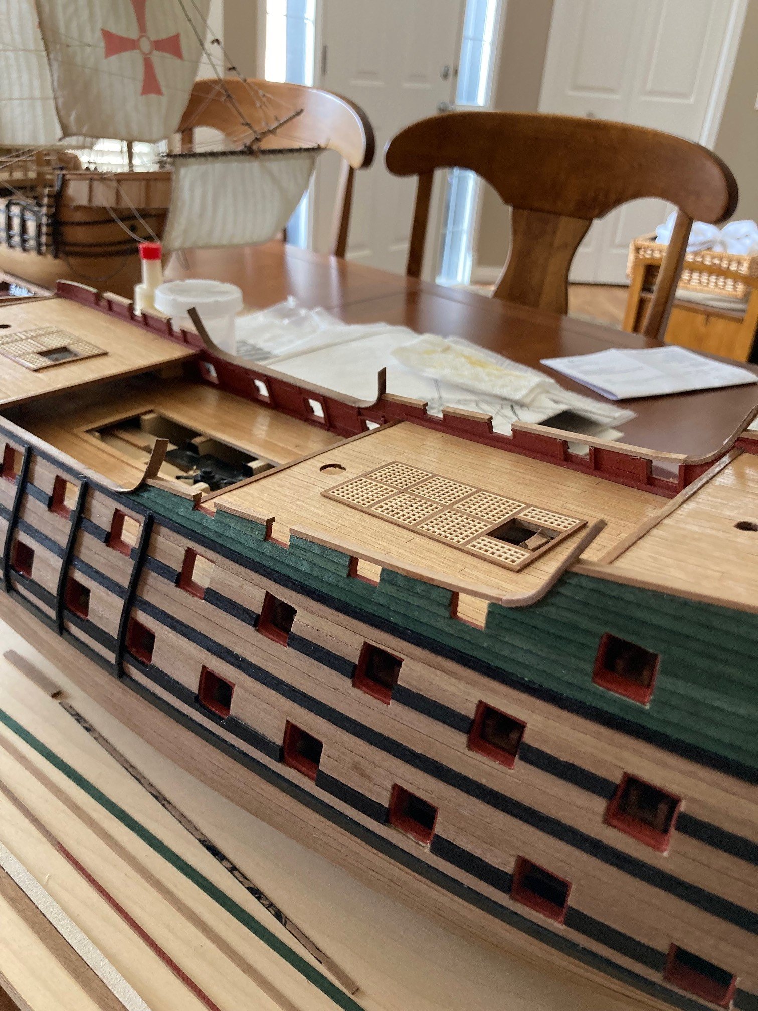
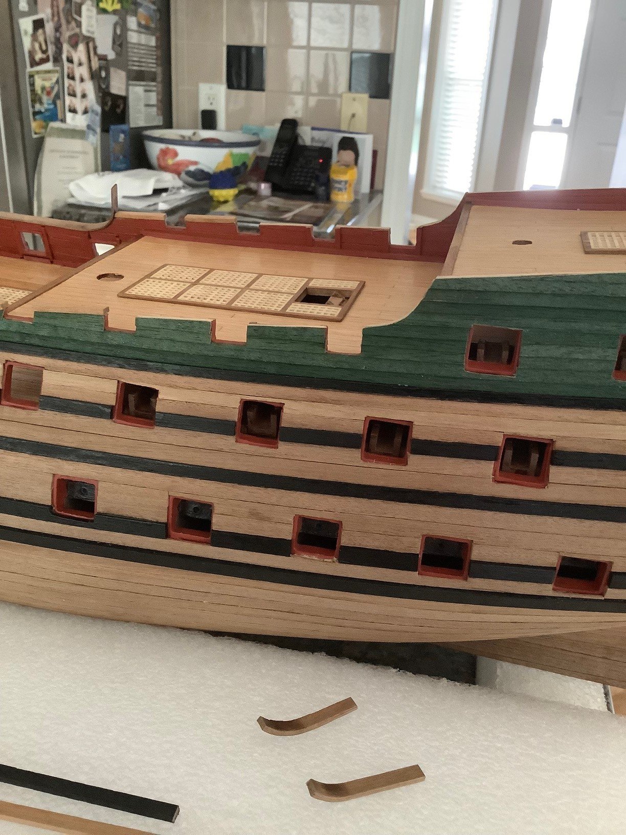
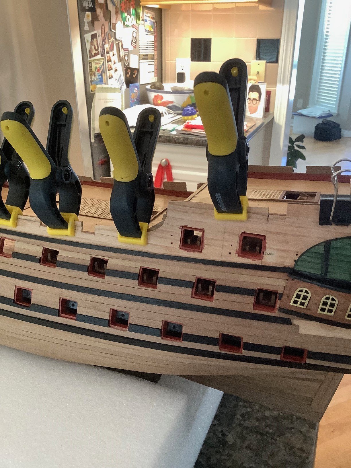
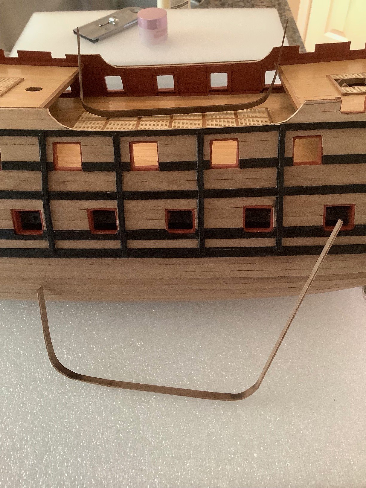
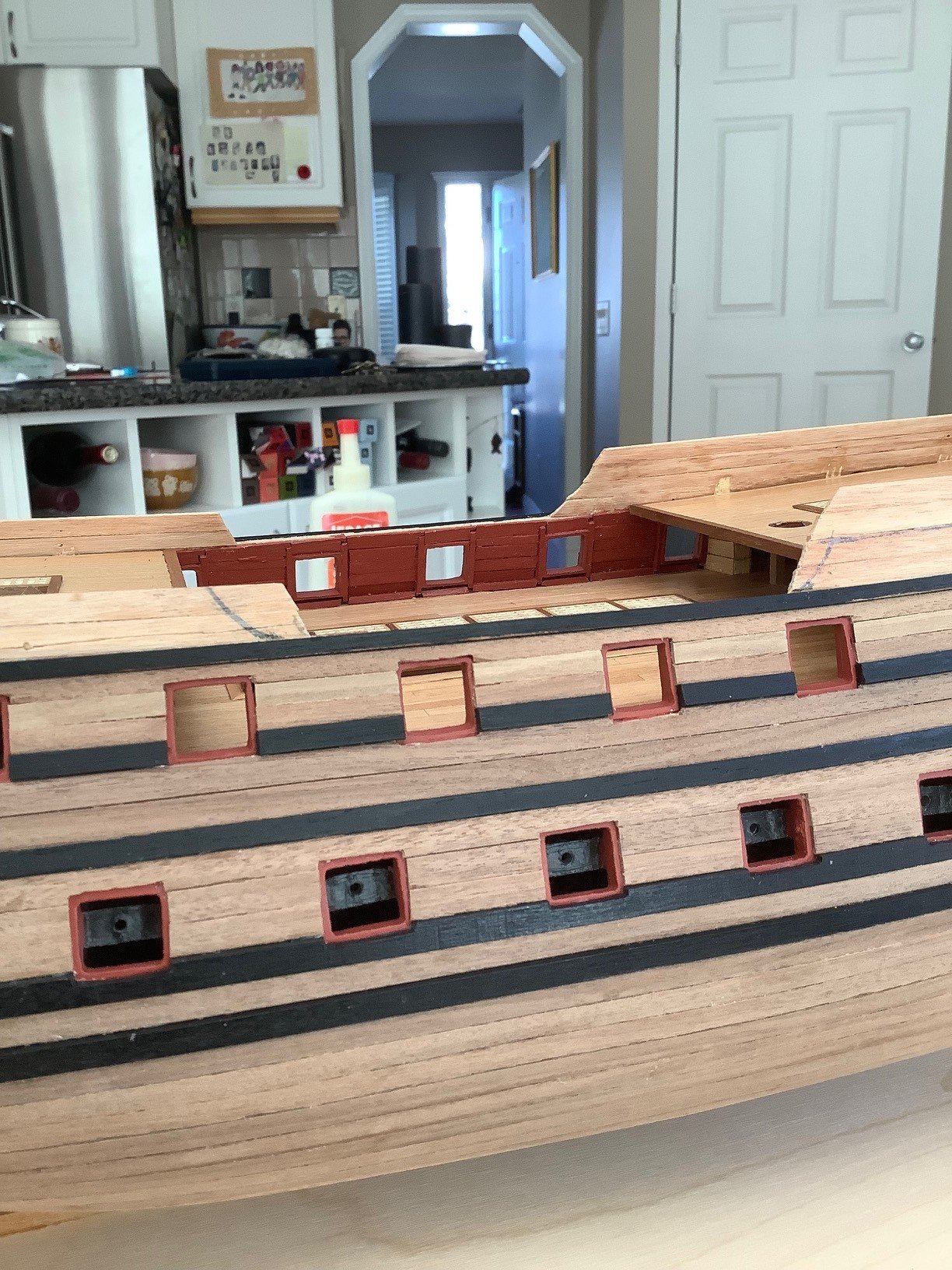
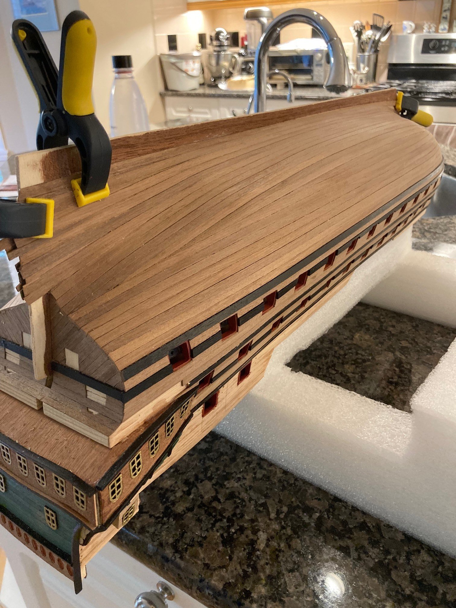
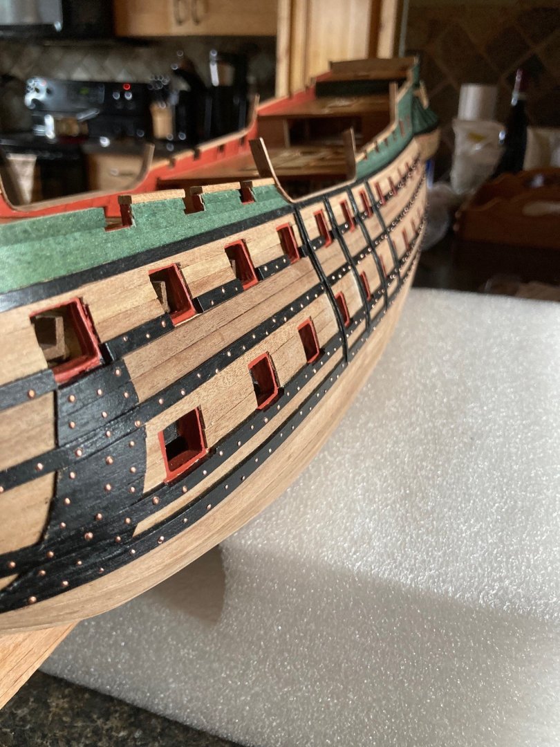
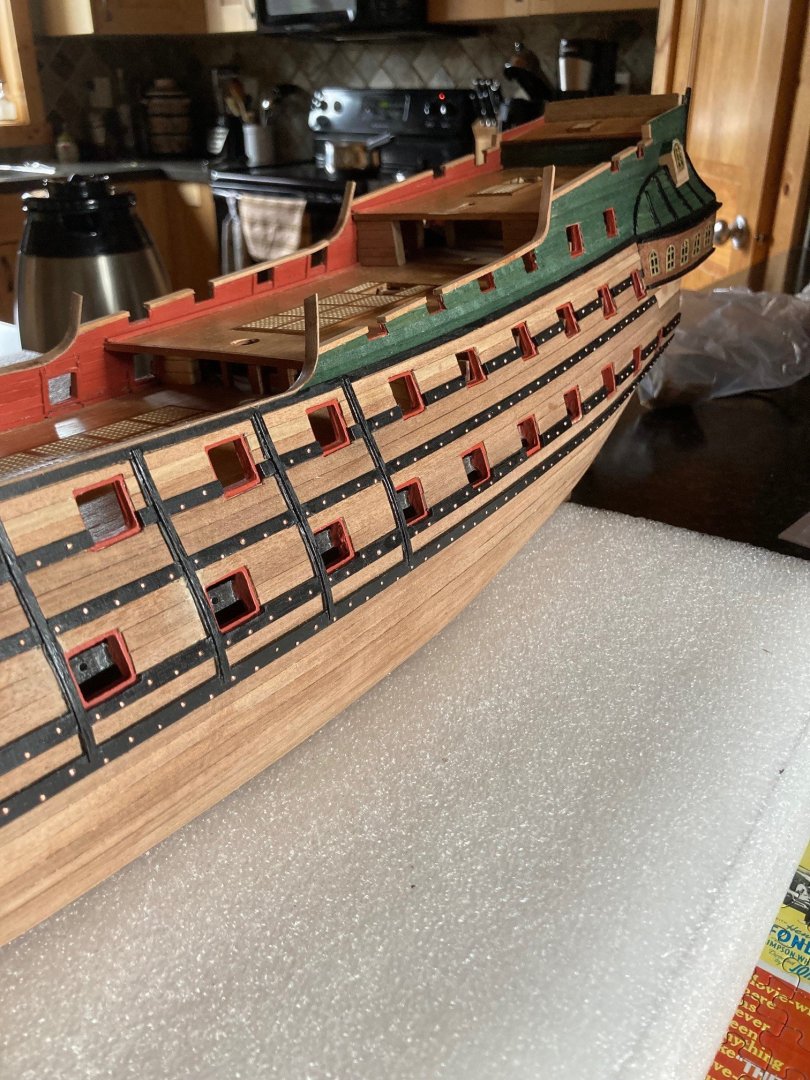
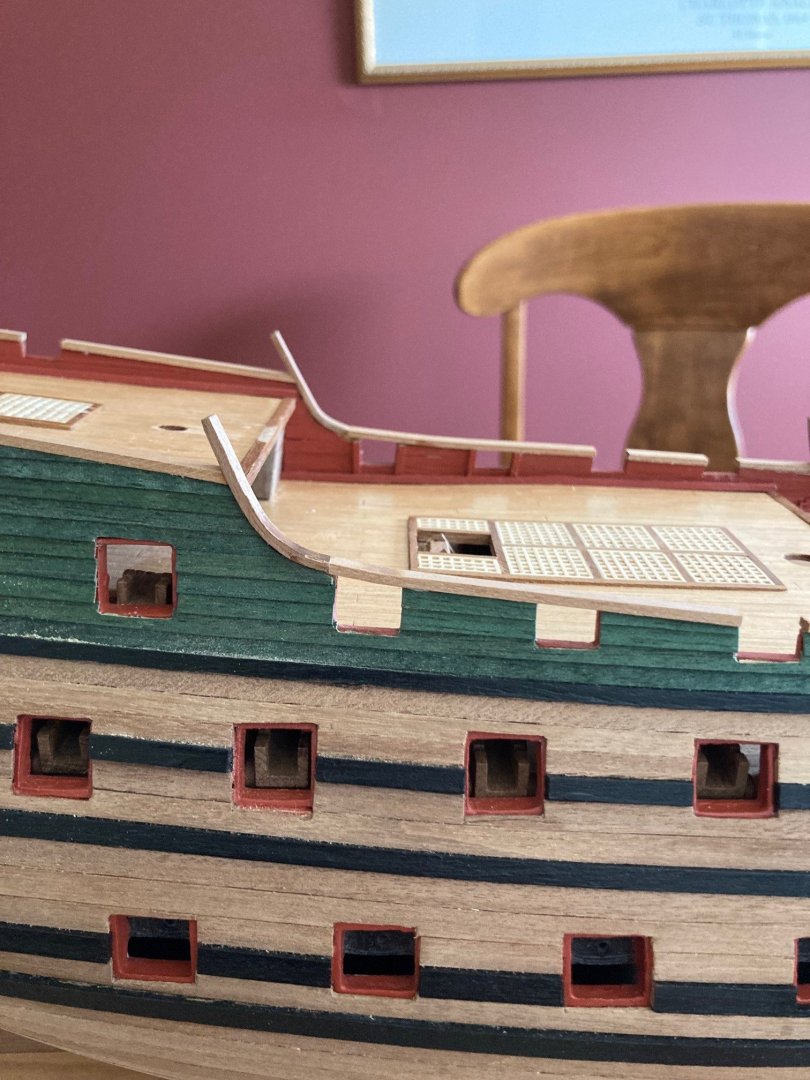
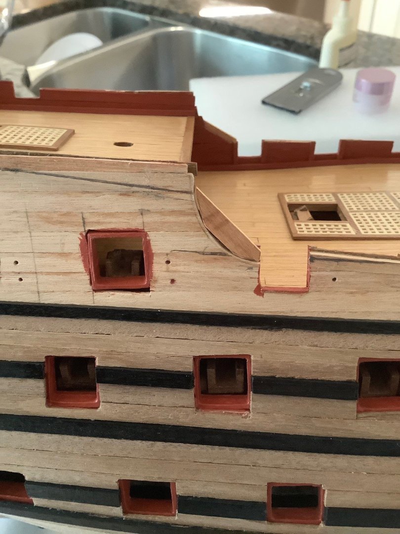
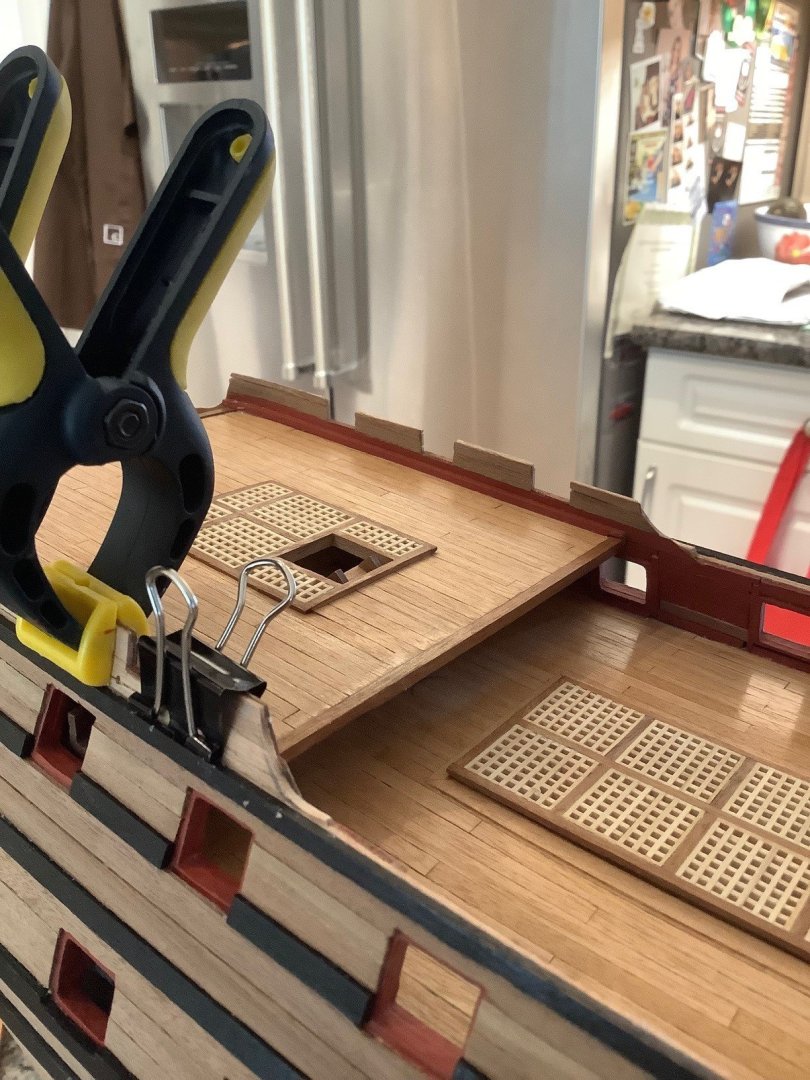
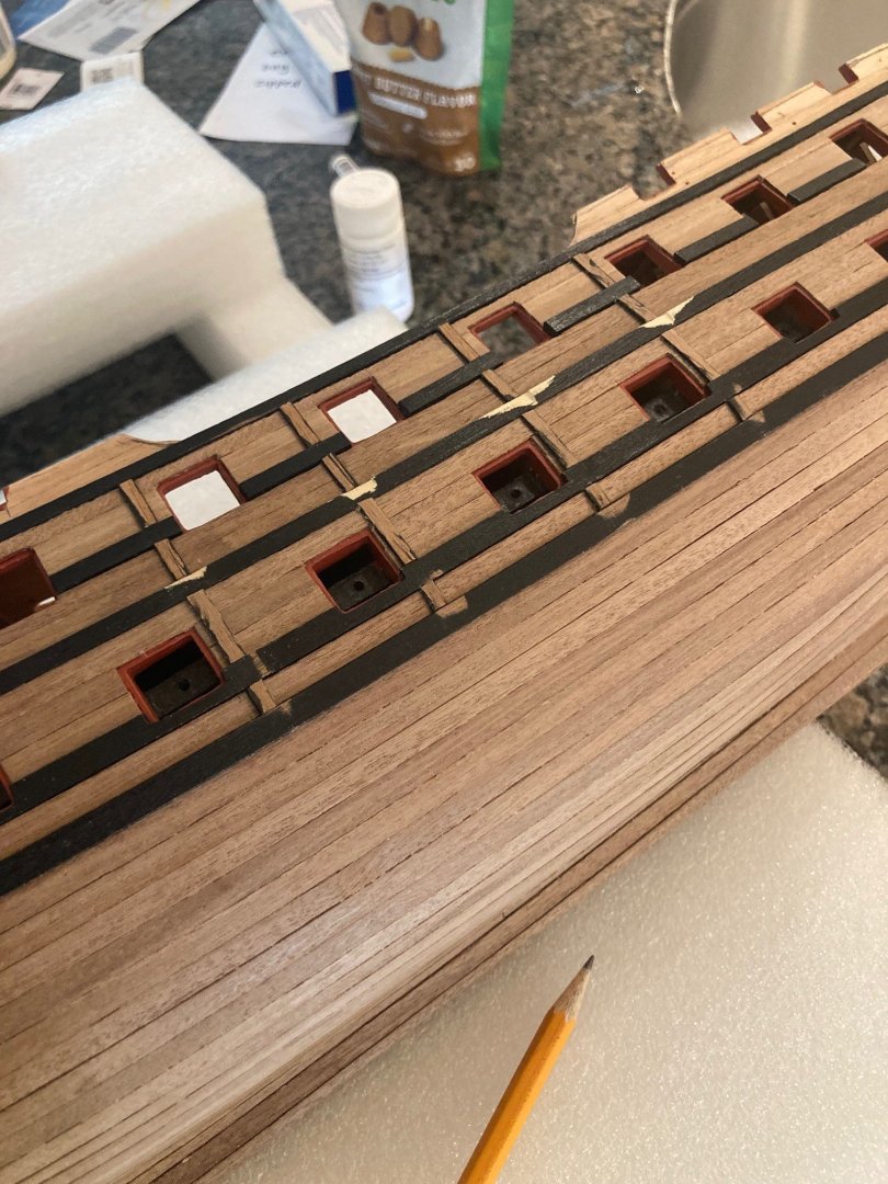
Lots of work getting the upper deck gun ports at the correct heights from the deck, relative to each other and from side to side, also making sure to get a flat run for when the deck railing caps go on. Also getting the correct profiles for the deck railings, with the specific challenge at the points of curved profiles, especially matching to the opposite side. Took lots of measurements from the plan, transferring, changing, and remeasuring, having to add and sand back in some cases from the initial hull planking that I did. Luckily the gun ports were initially located correctly from side to side to each other from my measurements from an earlier stage of the build when first rough cutting them out. Once satisfied, I started the upper side wall planking with the stained planks.

-
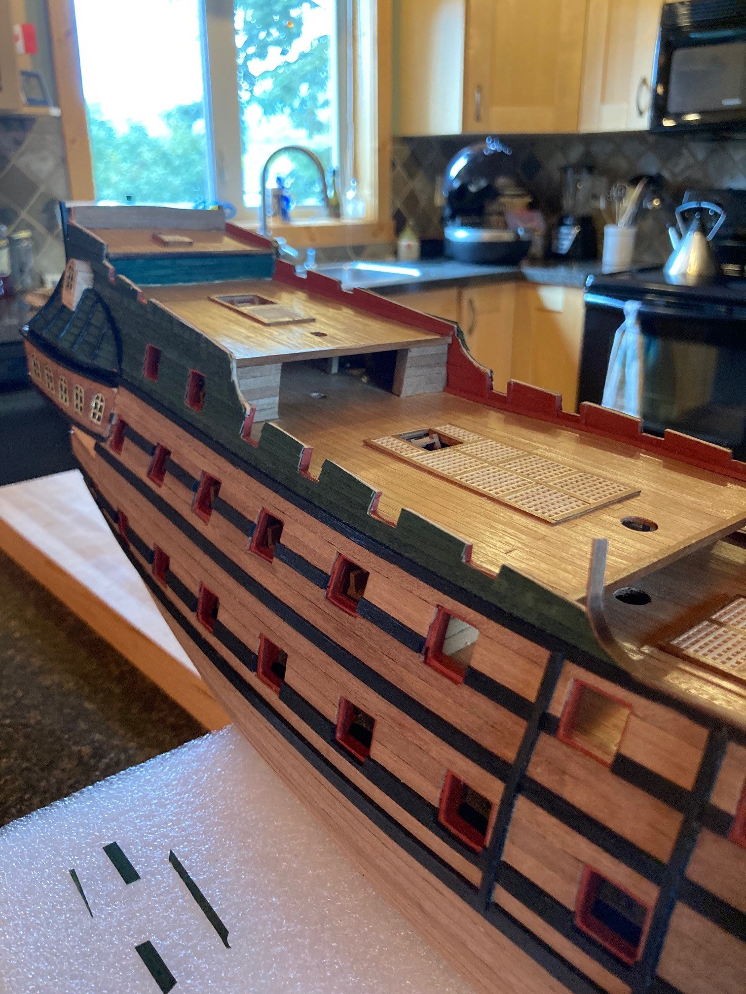
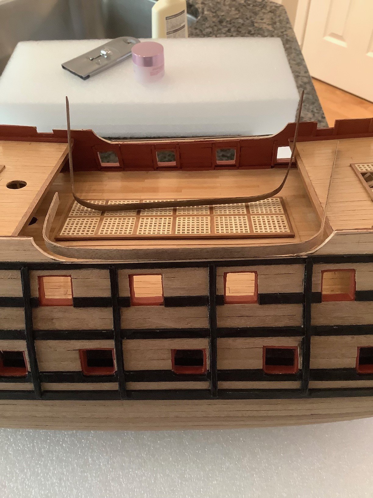
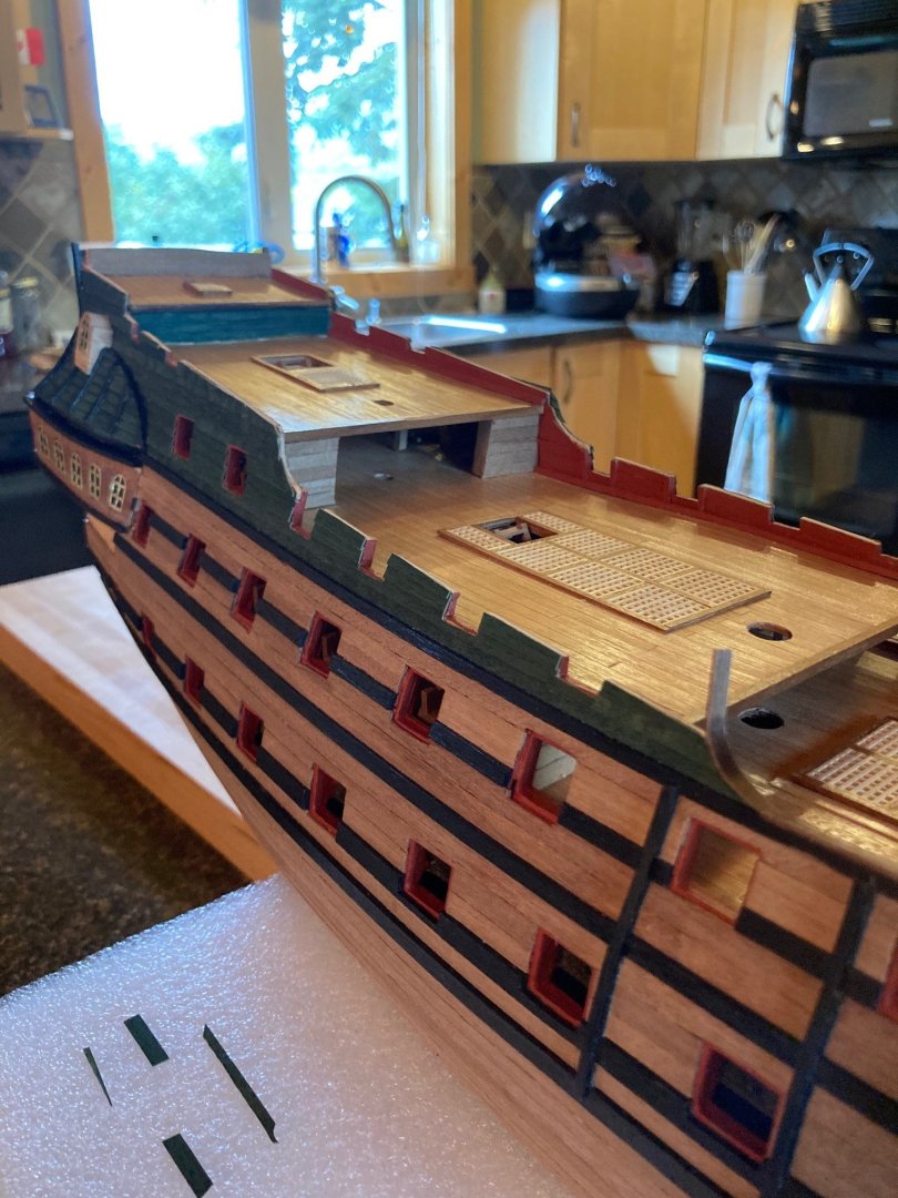
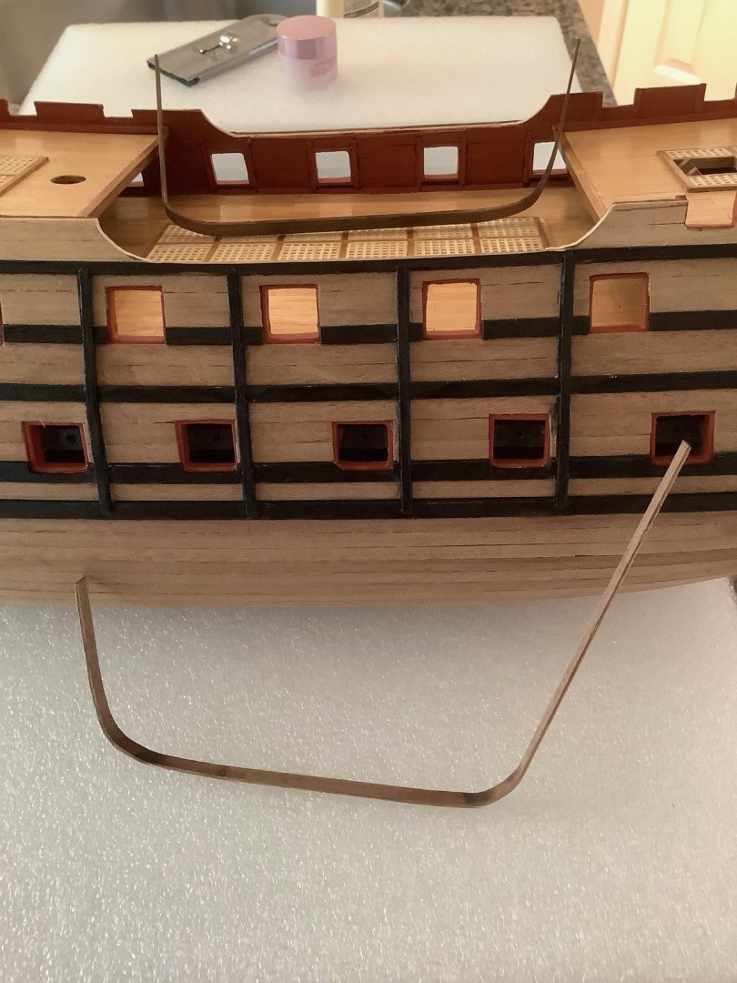
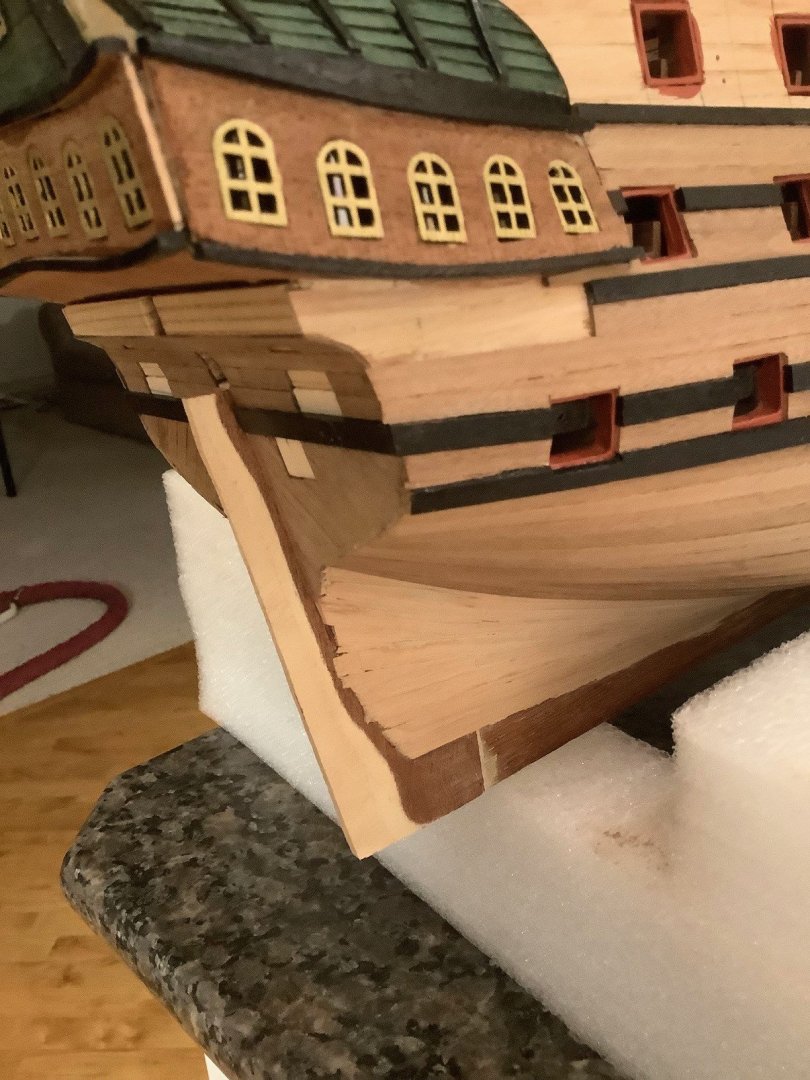
Lots of work since my last posting... Planked the inner bulwarks and began painting them red ocre. Also worked on the rubbing strakes as well as the main deck railing with the bends achieved with a heated plank bending tool. Happy with the result but need to do a bit of black touchups.


-
Thanks for sharing your build log... Excellent result!
- 426 replies
-
- 2
-

-
- Vanguard Models
- Sphinx
- (and 1 more)
-
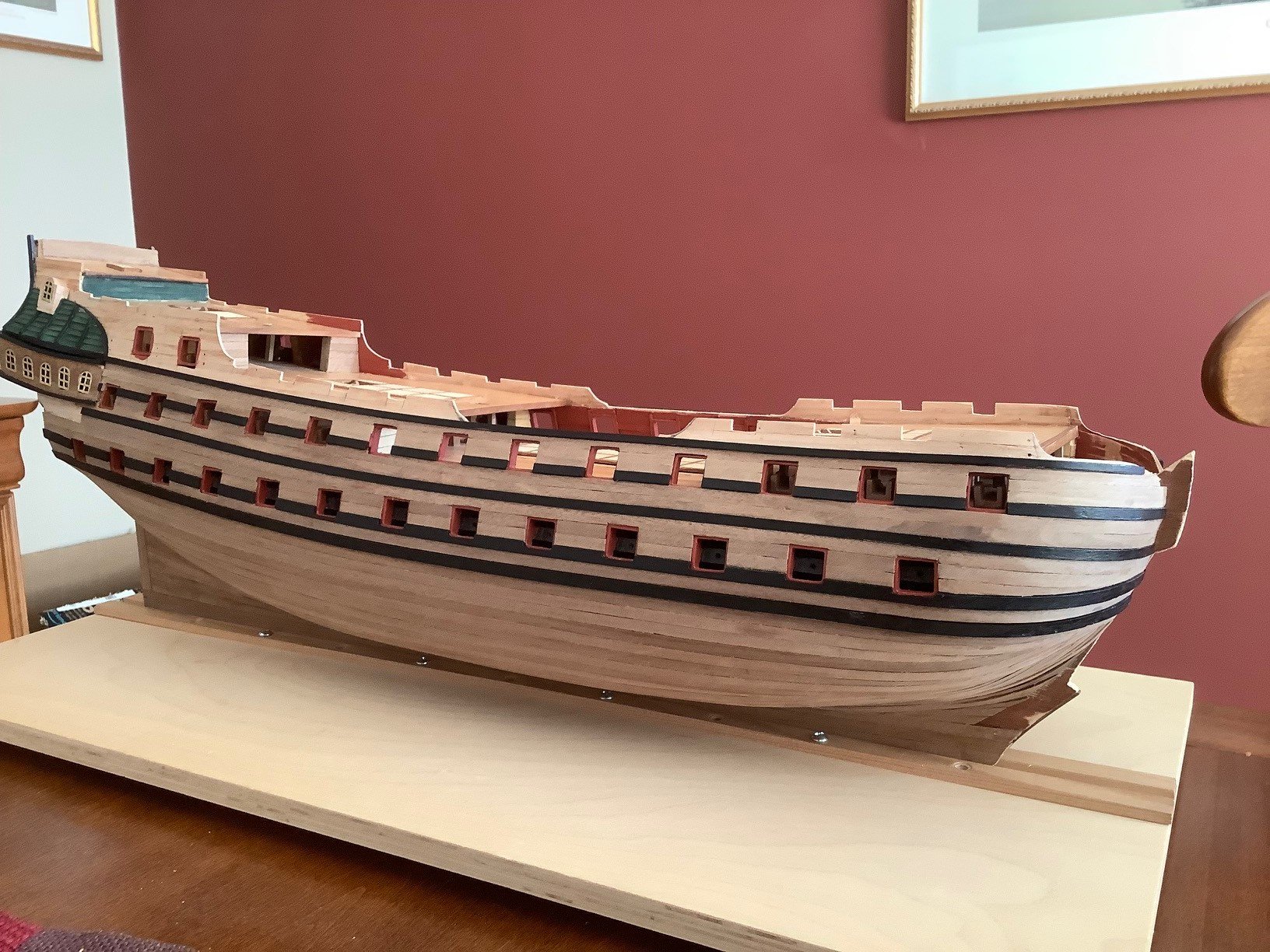
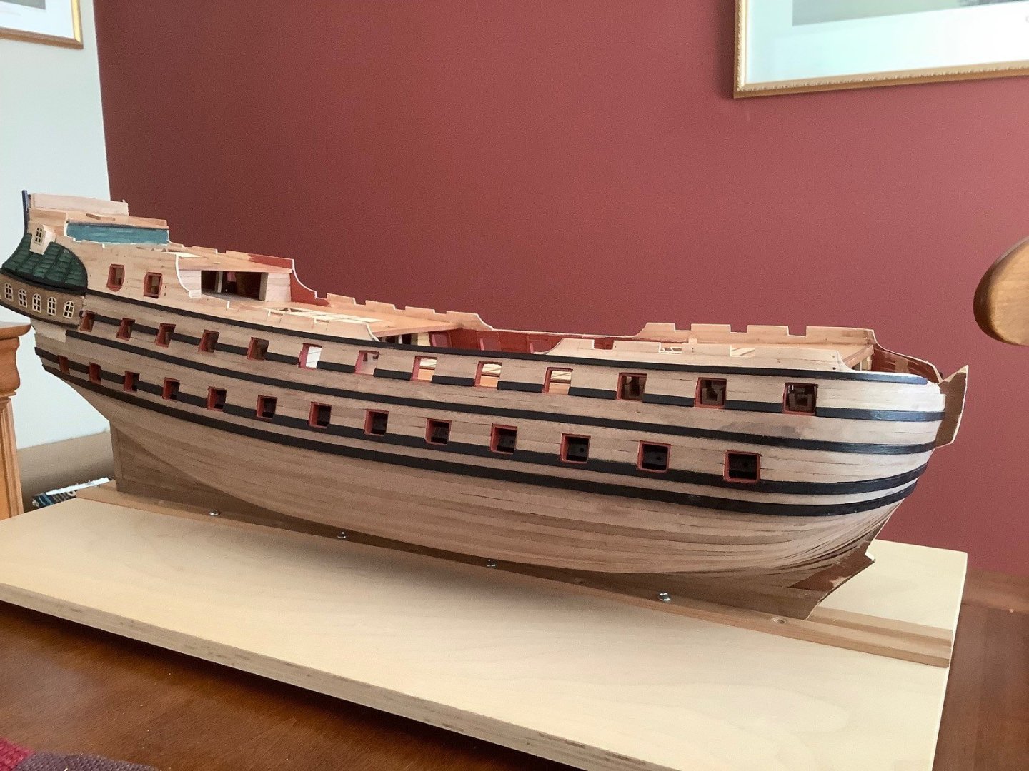
Reached a milestone in that the hull planking is complete. I bought some walnut filler and will at a later time fill some of the wider spaces between some of the planks at the bow but overall happy with how the planking turned out. Also started to transfer the measurements from the plans to the hull, preparing the upper profiles, for gunports on the upper decks.


-
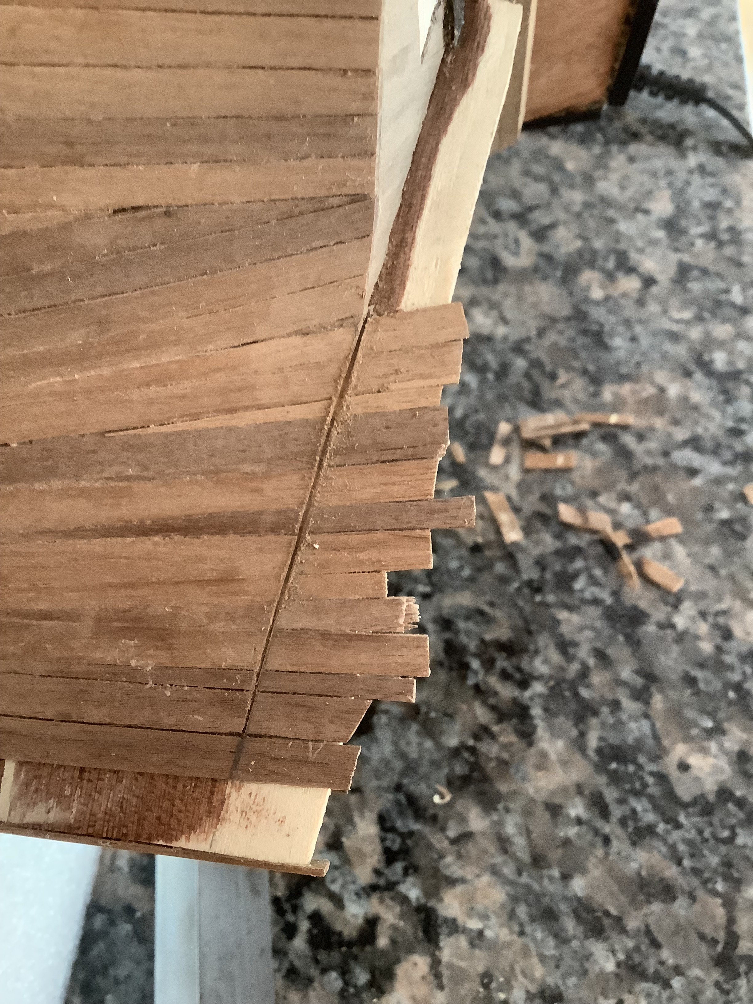
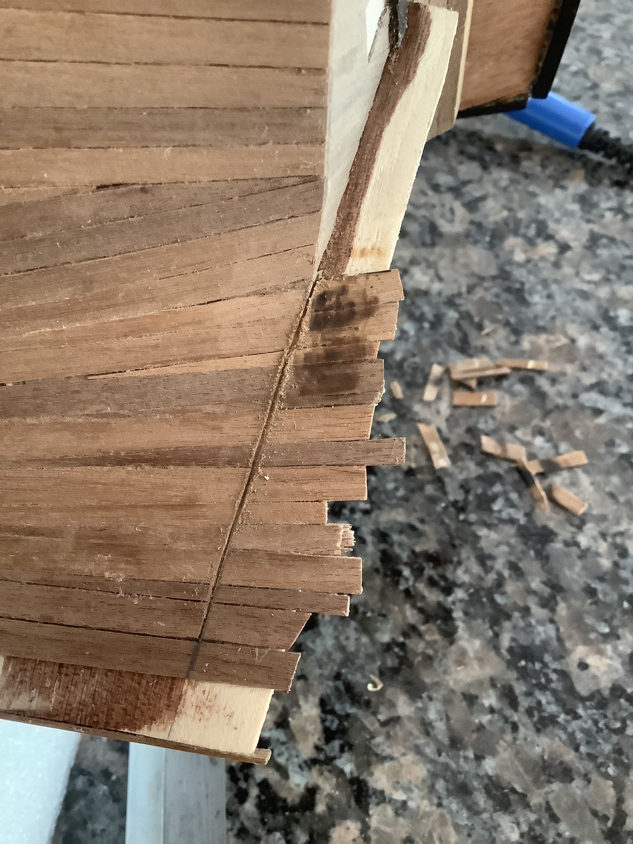
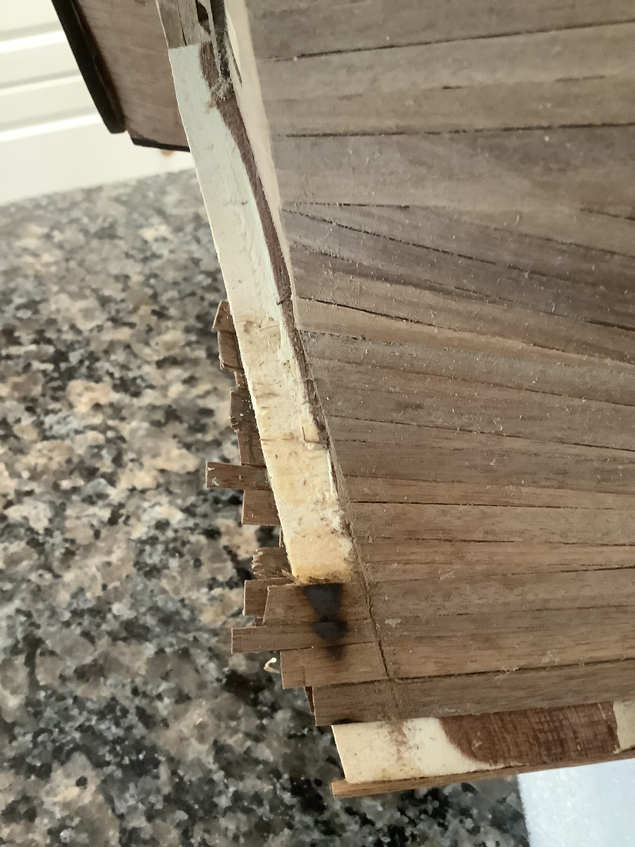
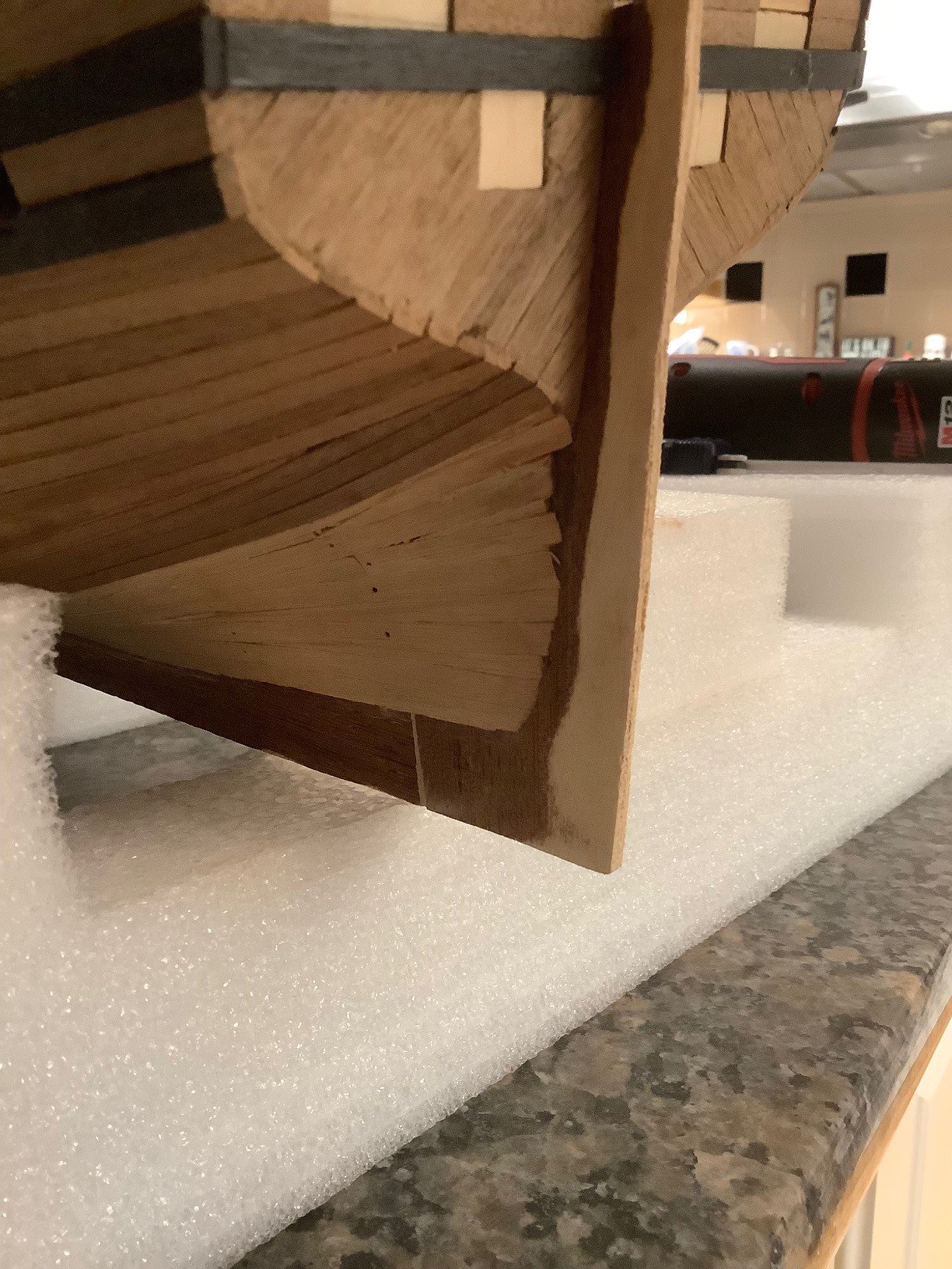
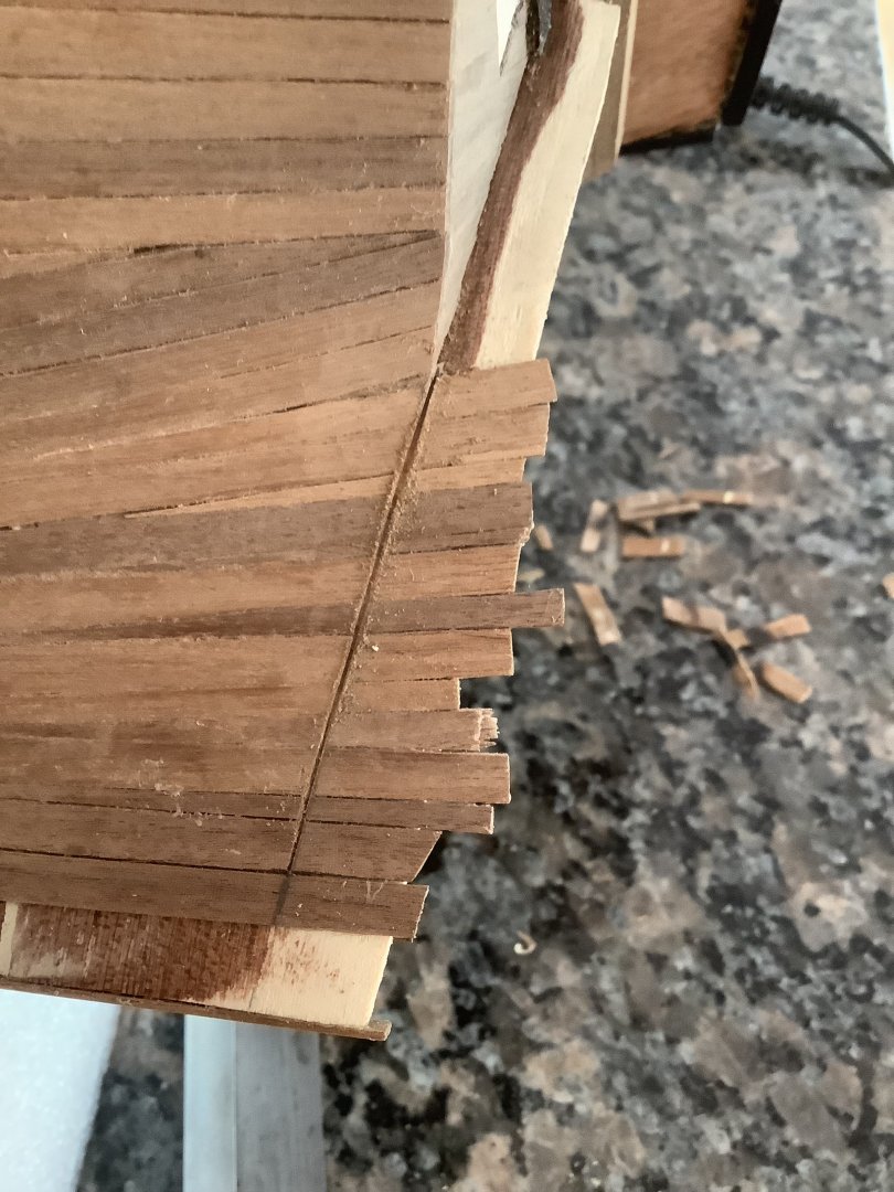
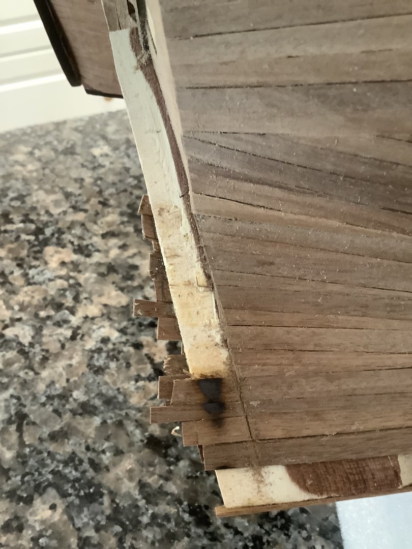
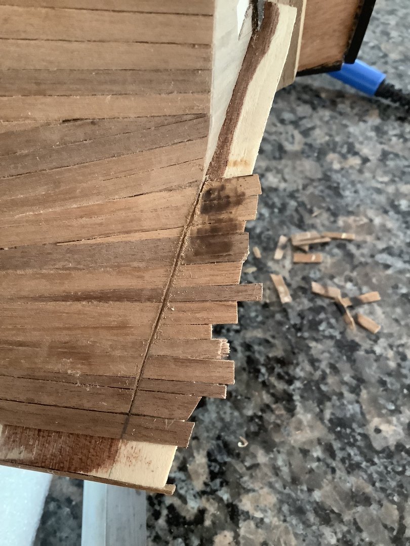
Cleaned up the sternpost to allow for the vertical planking. Used heat to release the wood glue from the ends

-
Mistake on Sternpost Planking
mrcc replied to mrcc's topic in Building, Framing, Planking and plating a ships hull and deck
Much easier that I thought... marked the forward edge of the sternpost line, scored a line with a blade, heated up the plank portion in order to release from the glue, and the plank end lifted up effortlessly.

-
Thanks Patrick... Yes, I have seen this build log on the Dutch forum. Thanks for sharing...
-
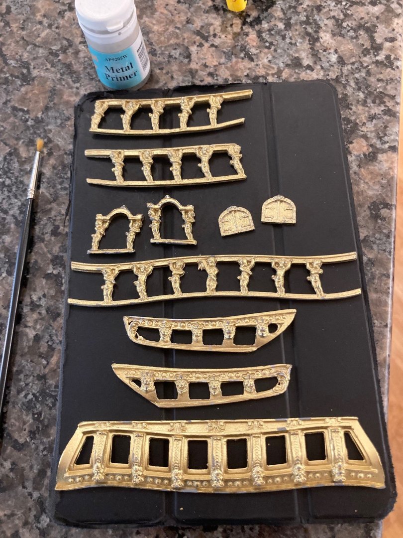
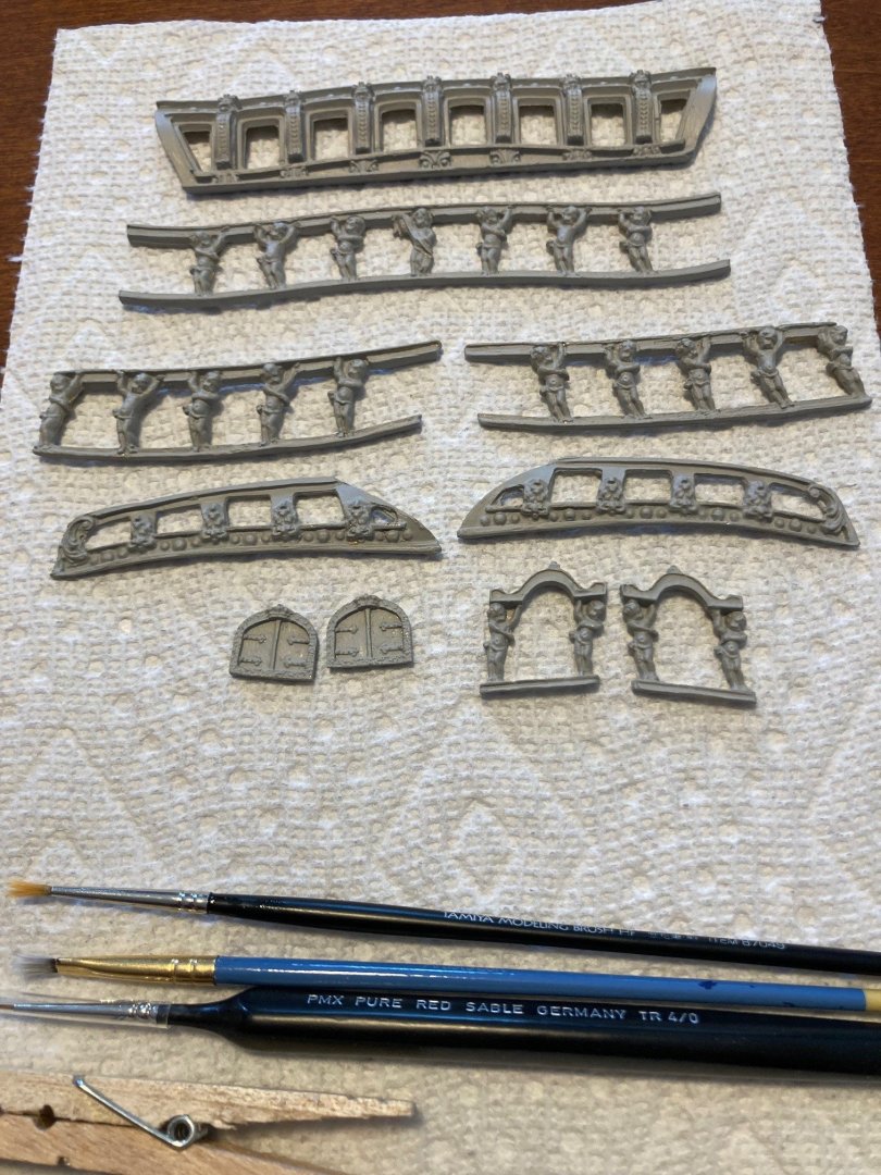
Still some small plank pieces to lay at the bow and along the keel, but almost done! Little diversion though with the castings at the stern; applied the metal primer and getting ready to paint... I am very unsure of the painting scheme at the stern as all sorts of different options on Google images. My preference at the moment may not be historically accurate??? PS These casting are probably 40 years old and given the molds were relatively "young" at the time of casting, I have to say the primed stern decorations look very good to me.

-
Wonderful build log Clare… I love how the Mamoli kits build out. Thanks for sharing!
- 82 replies
-
- 1
-
-
- Yacht Mary
- Mamoli
- (and 1 more)
-
Mistake on Sternpost Planking
mrcc replied to mrcc's topic in Building, Framing, Planking and plating a ships hull and deck
I know… strange! -
Mistake on Sternpost Planking
mrcc replied to mrcc's topic in Building, Framing, Planking and plating a ships hull and deck
Thanks TMJ for your advice… yes I used PVA glue on the planks and I will take your advice of heating the planks after scoring a line where the stern post should be, and then trying to lift off the ends. PS strange that I received your advice via email but yet your reply/post will not show on the MSW web log - even after, what 10 hours. -
Mistake on Sternpost Planking
mrcc replied to mrcc's topic in Building, Framing, Planking and plating a ships hull and deck
Thanks TMJ... good advice and I may end up doing that but I think I will first try and delicately cut back those flared planks with a razor blade and fine chisel. -
Mistake on Sternpost Planking
mrcc replied to mrcc's topic in Building, Framing, Planking and plating a ships hull and deck
Thanks Bob... Even if painting, sometimes you can see trace planking outlines and if painted, still need to tie into the stern post above the waterline... -
On my Mamoli Friesland build, I should have left the sternpost bare for vertical planking but realized late of my error. Question is pull it off to the sternpost line or leave as is as I was going to paint the waterline and below all white (which will cover the error)?

-
Close to the finish line...


-
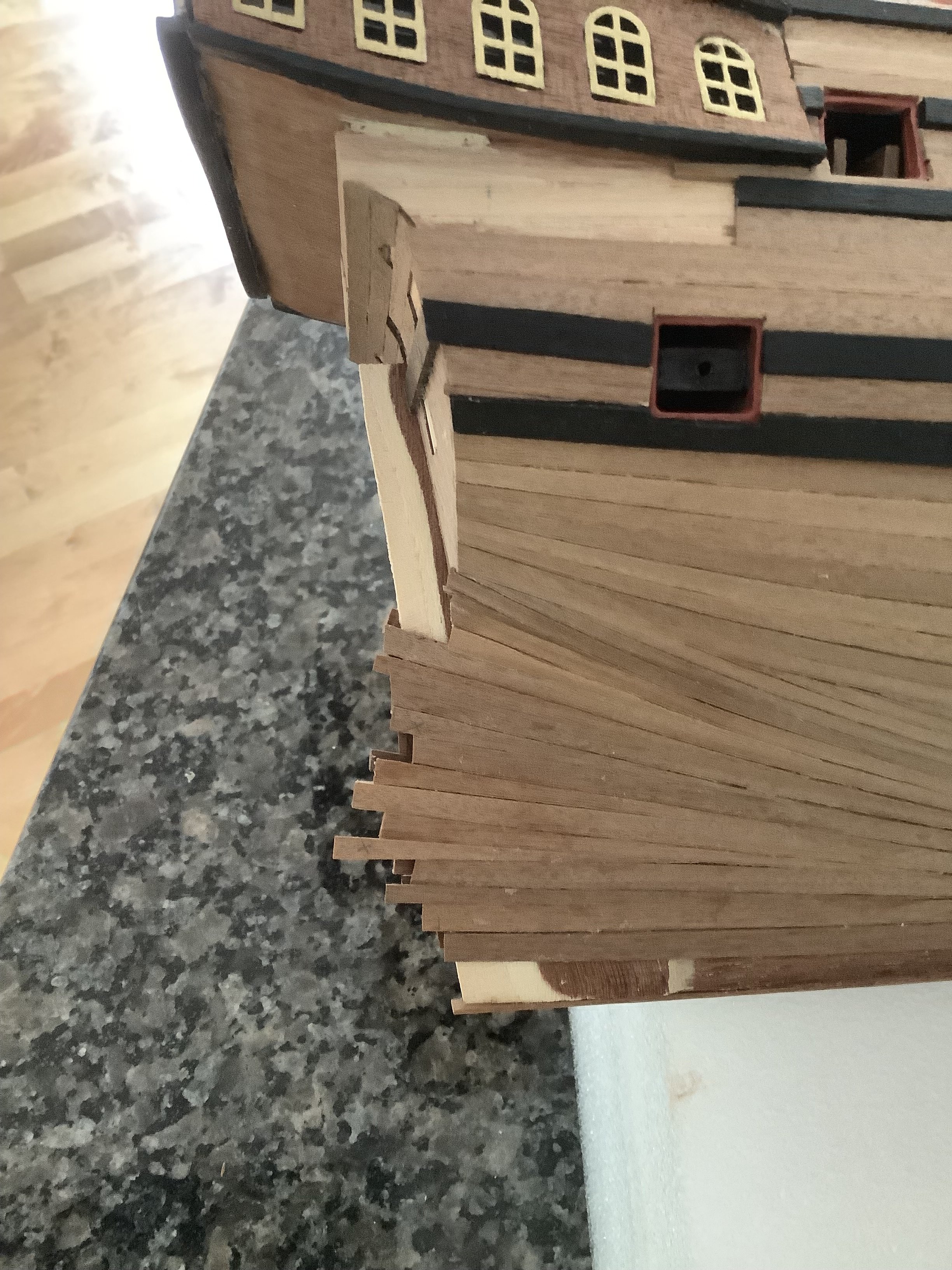
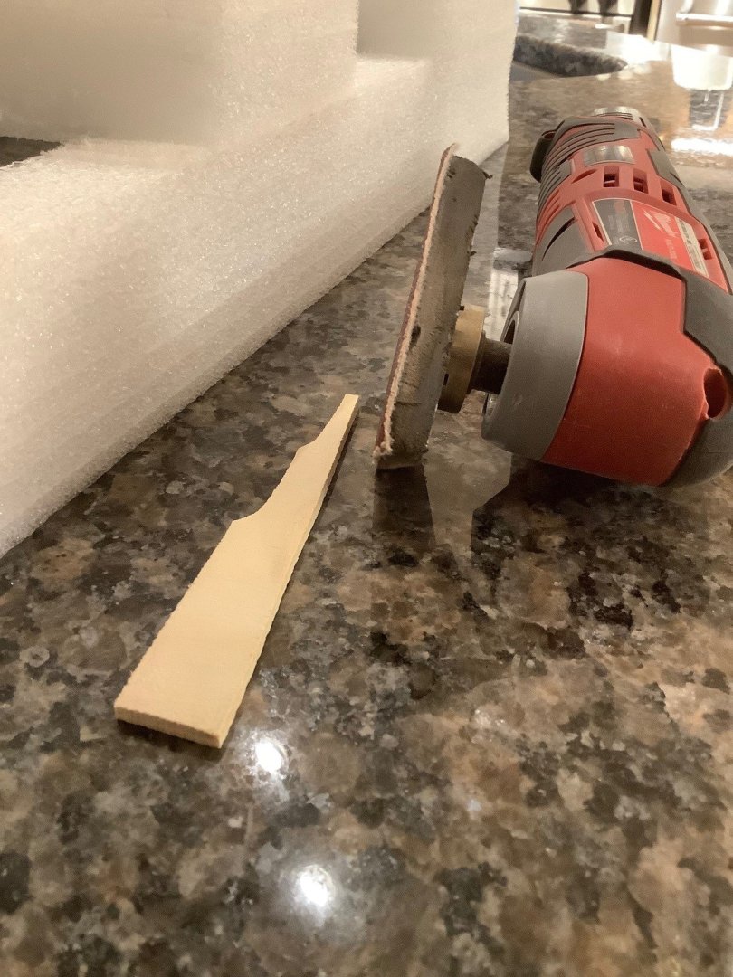
Thanks Zappto... I really appreciate you checking in on my build log! Some progress on planking but it has been a slow go as busy with work and then away on holidays for 2 weeks in Greece. Anyways here is some progress... I did have to taper the rear stem post as I decided to completely plank the post and rudder and you need to taper back down to account for the thickness of the planks otherwise the pintles won't fit. Nothing noted in the instructions but do know this from my previous Mamoli Santa Maria build. Same for the rudder... Definitely need some fill between some planks in some areas of the hull. I think I did a better job of planking on my previous Santa Maria build.

-
Great job, nonetheless… Mamoli kits of old were such but they always seem to build out to a nice finished state. Good luck!
-
Thanks Ronald for checking out my build log… Yes, my wife is Dutch and well aware of the Fryslan connection. Her ancestral roots are from Rotterdam. We are in Holland from Canada every 3-4 years for a visit.