mrcc
-
Posts
572 -
Joined
-
Last visited
Content Type
Profiles
Forums
Gallery
Events
Everything posted by mrcc
-
Luckily my low back is very strong! Thanks for the replies...
-
 Thanks Henrik for your reply… the information is much appreciated! Cheers!
 -
Thanks for your input… Mamoli’s instructions for rigging is over 4 sheets and each sheet references additional blocks and items to attach to the masts and yards. I will really have to study them in detail so I don’t miss anything.
-
Thanks Rich, thanks Pfalzer! I have a “game plan” at this time and appreciate your help and suggestions.
-
Thank-you for your input! I appreciate it...
-
I have a couple of kit builds under my belt, but not sure how to do masts that have multiple elements to them. I scoured this specific section of MSW without a clear understanding. The question is glue the lower portions of the masts FIRST, securing them in their respective mast holes in the deck and then build the top mast, and then the top gallant mast subsequently (adding all the blocks and fittings as you go up at each section of the mast), making sure all are in proper alignment as they build up or whether to build the entire masts off the deck and then place them? Not sure on my Mamoli Friesland what is best or ideal given the very limited instructions on this matter?
-
Wonderful build Henrik… read your build log from beginning to end. One question, you mentioned dry fitting the upper portions of the masts, but at this time, are all your lower portions of the masts glued and secured in their mast holes in the deck? Not sure on my Friesland, whether to build the entire masts off the deck and then place or build up the masts from the bottom up, section by section?
-
Lynx by Gaffrig - Panart - Scale 1:62
mrcc replied to Gaffrig's topic in - Kit build logs for subjects built from 1801 - 1850
Everything is very nicely done! -
Thanks Peter, Thanks Bob!
-
Thanks Patrick... I am quite happy with how it has turned out to date!
-
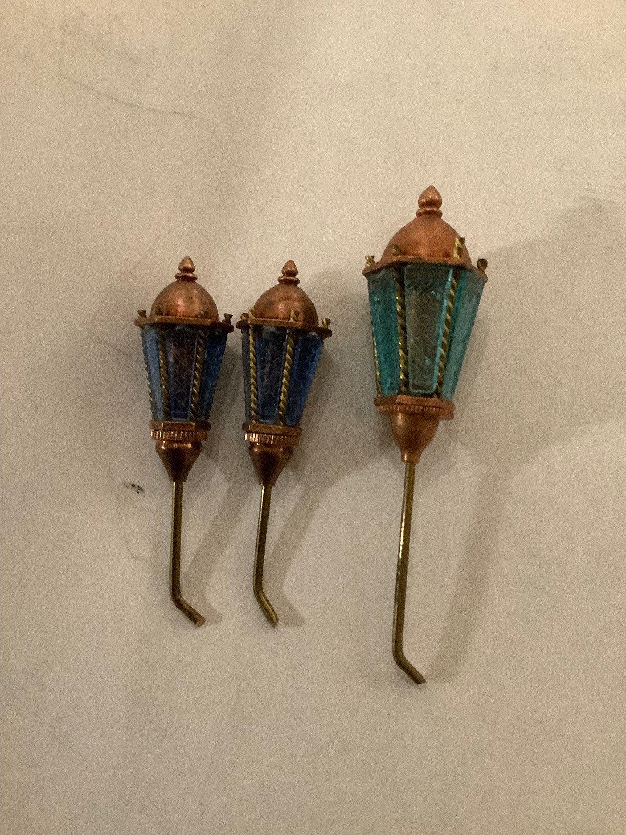
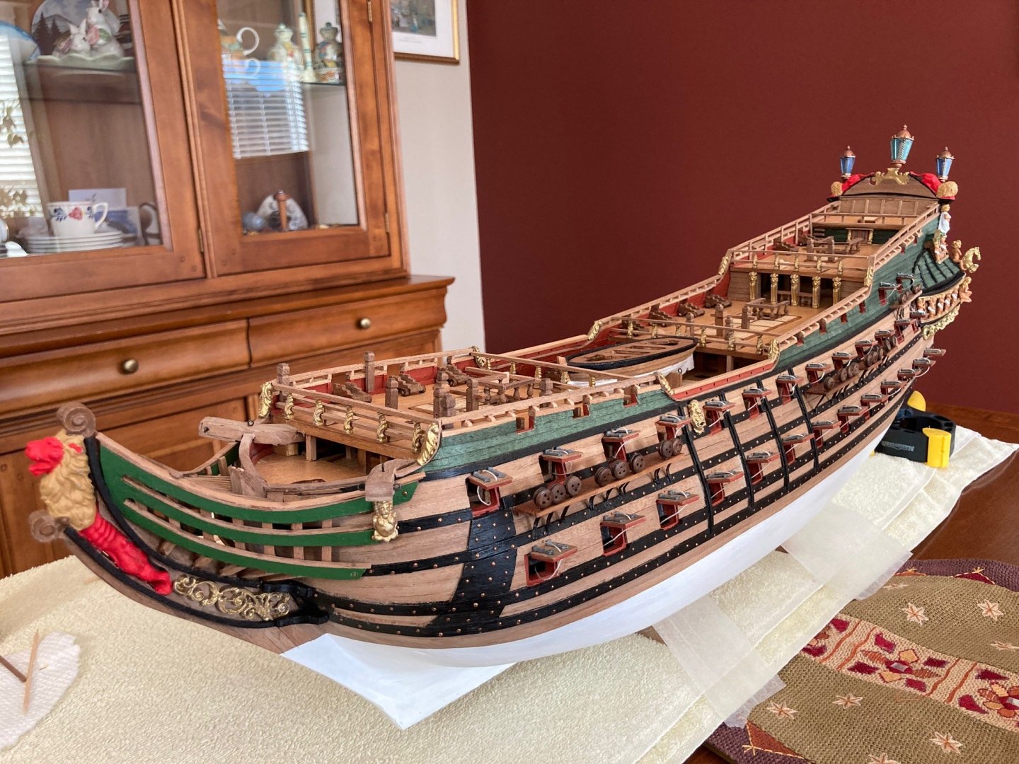
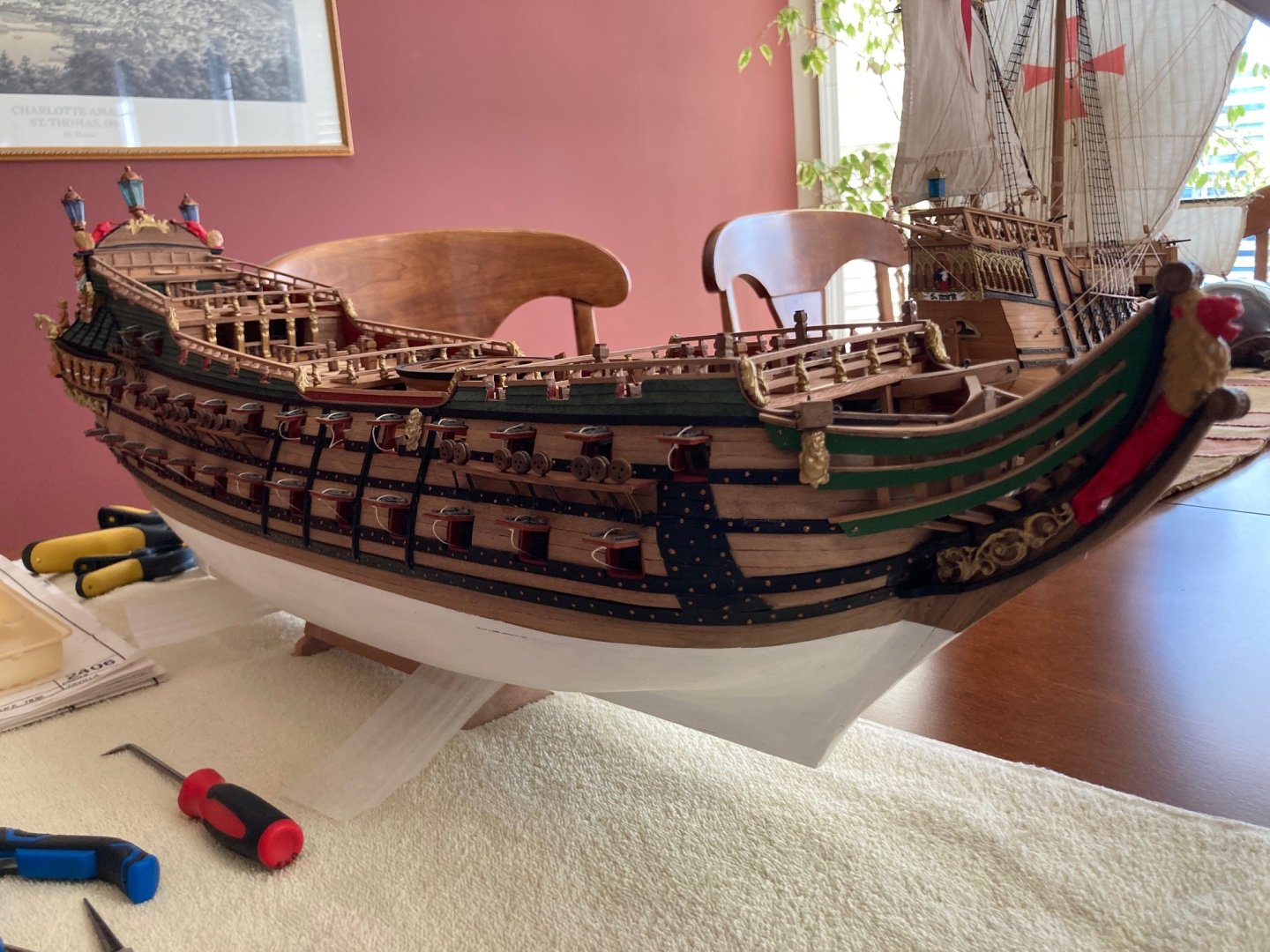
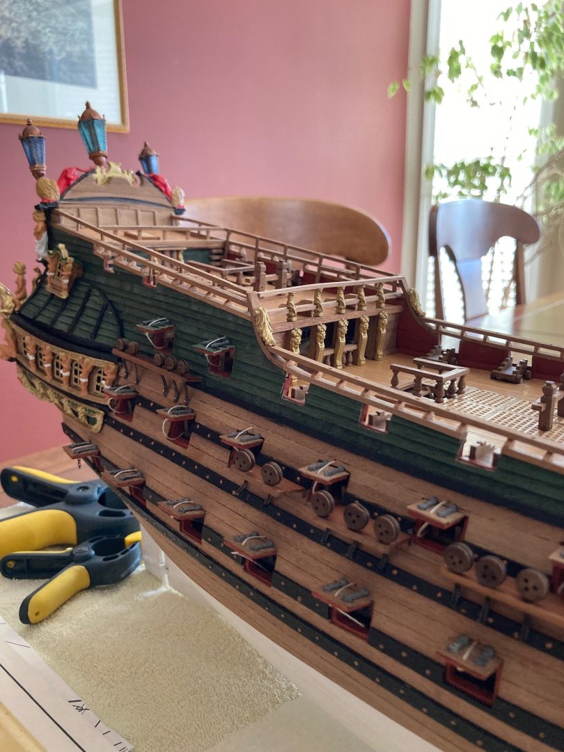
And some pictures of the full hull as she sits at this time... First though a closeup of the kit supplied stern lanterns before they were attached to the stern... very nice in my opinion. Shame about the different color of the panes on the large centre lantern. I told my wife I was going to take a big break at this stage of the build but last night I could not help but turn a few of the masts with the used Proxxon lathe that I bought roughly two years ago for this very purpose. It was fun!

-
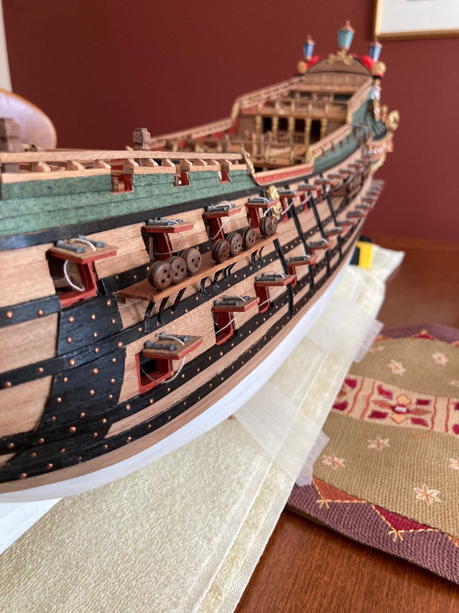
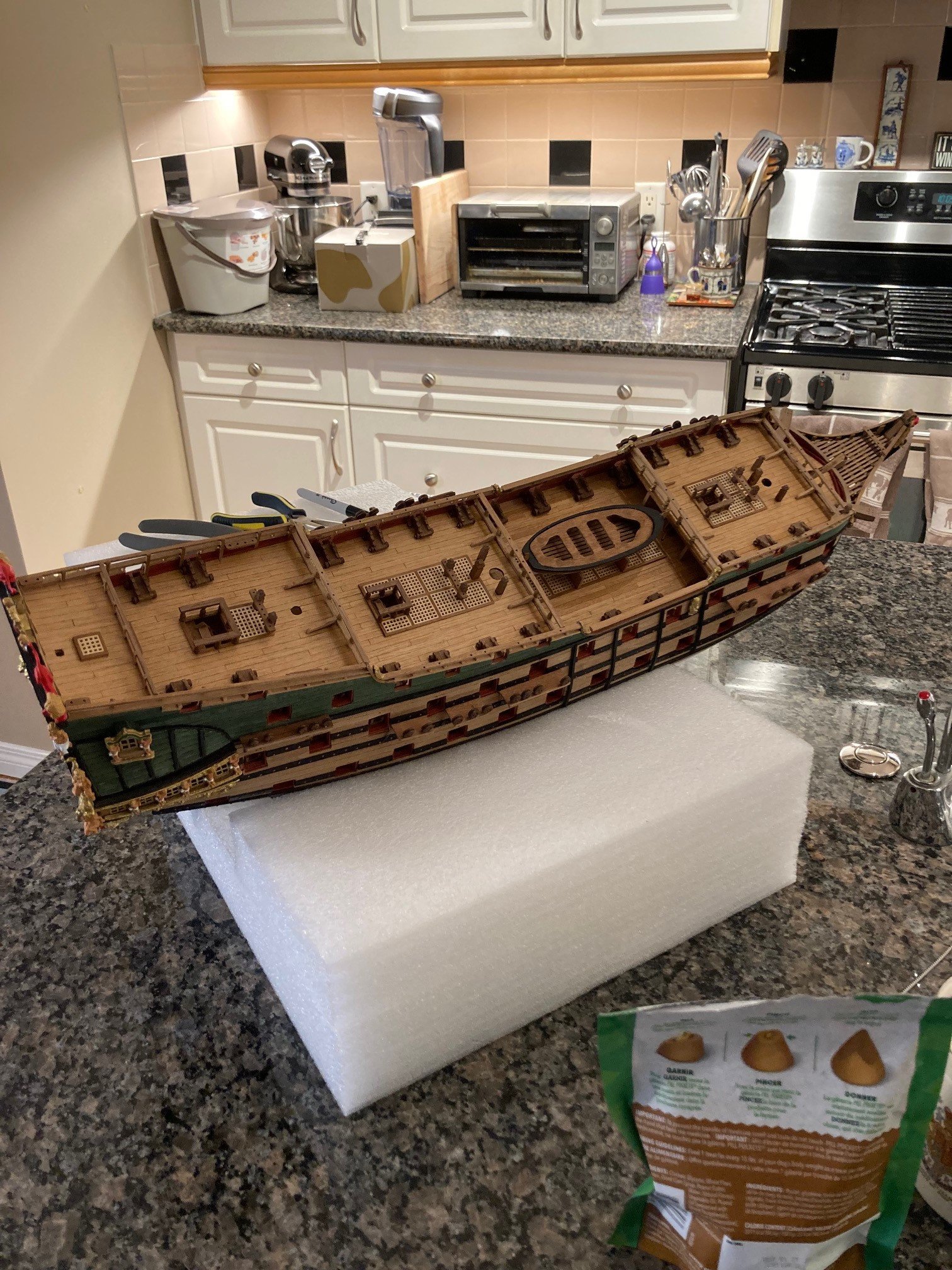
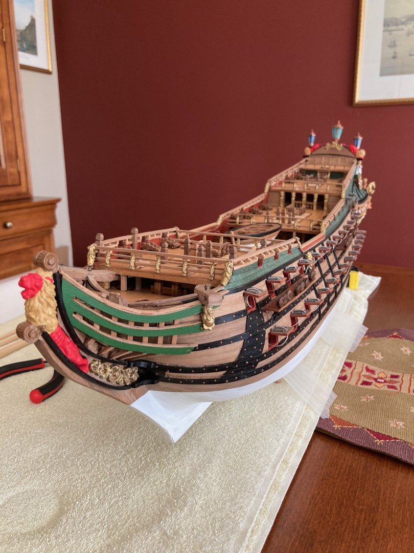
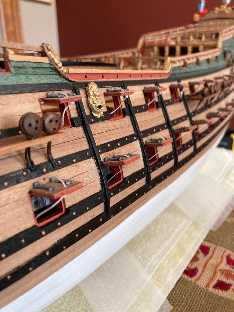
An update as I have now officially finished the hull. All the gun port lids are now attached and with the exception of all the cannons being installed onto their gun cradles, I am now ready for the masts. I am going to place the cannons at the very end of the build... There are additional fittings such as eyelets and ring bolts to attach to the deck and hull but their placement is more associated with the rigging stage of the build. I will likely pre-drill some of these holes for the eyelets and ring bolts at this time, before the decks get too cluttered.


-
I am one who would wait for a Vanguard Models HMS Victory, as they say in Canada and perhaps in other places, “till the cows come home”!
-
Finally some work done on the 4 anchors. I left them the natural color which I quite like and added 2mm Tamiya tape (that I first colored with black permanent marker) in order to simulate the iron bands. I had to do 3 passes with the black marker to get a full coloring.


-
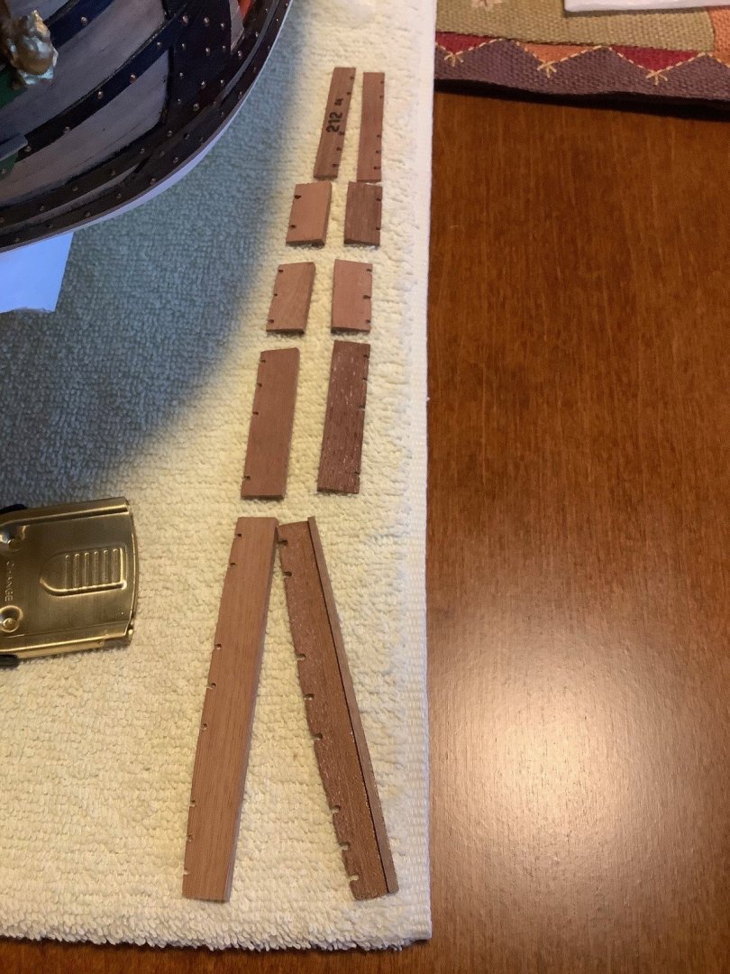
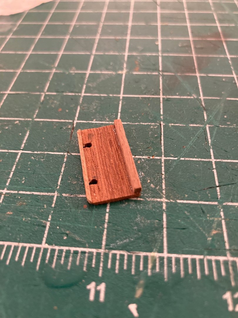
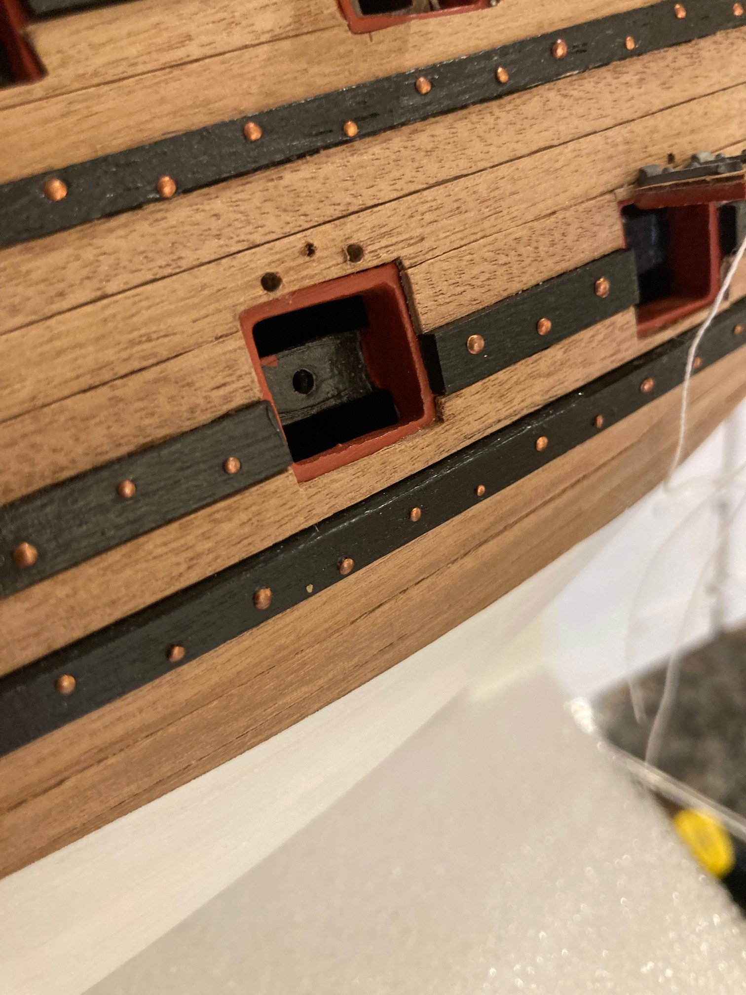
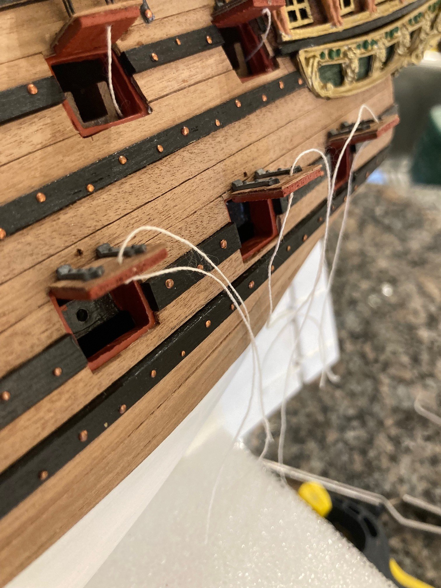
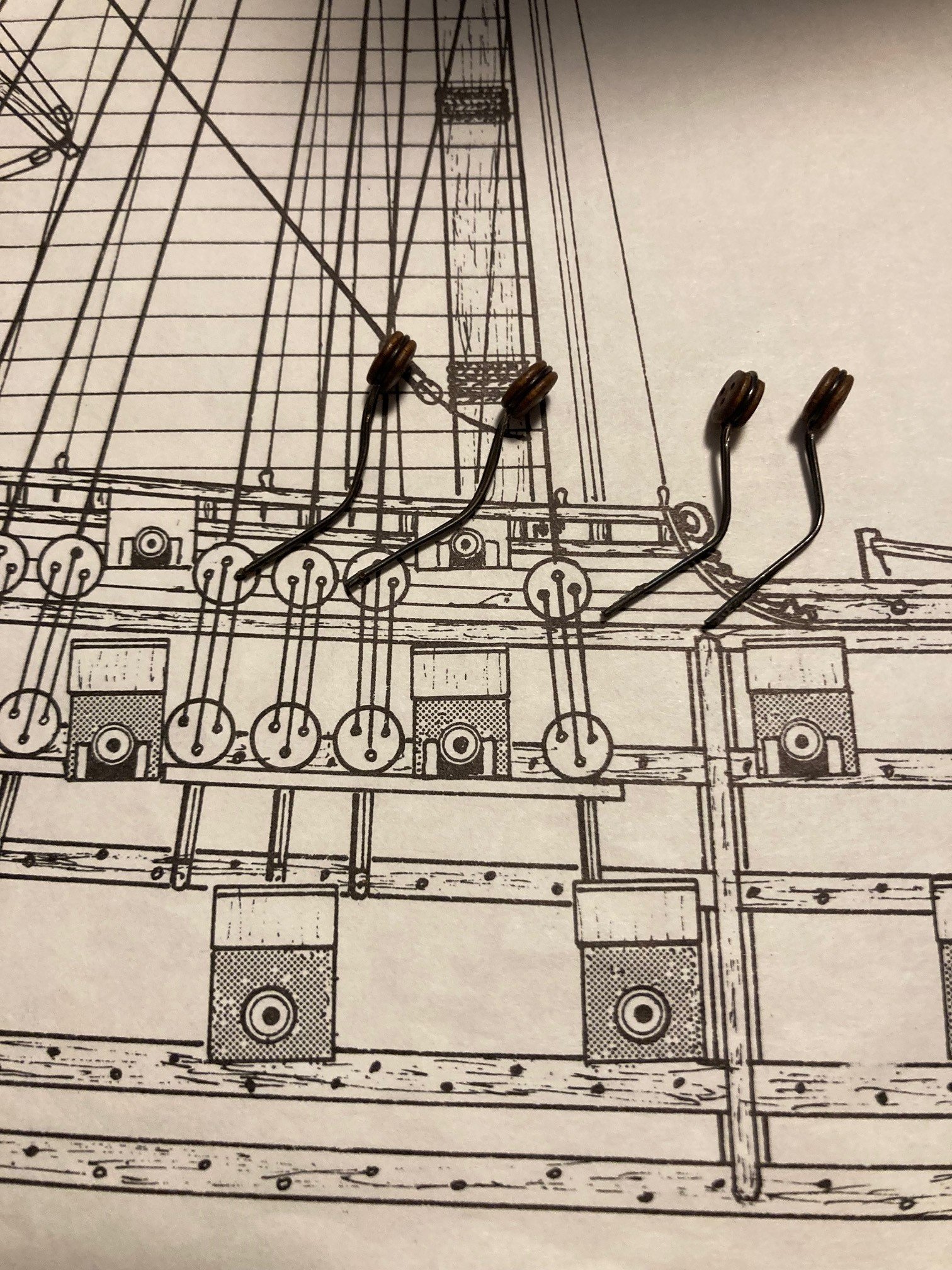
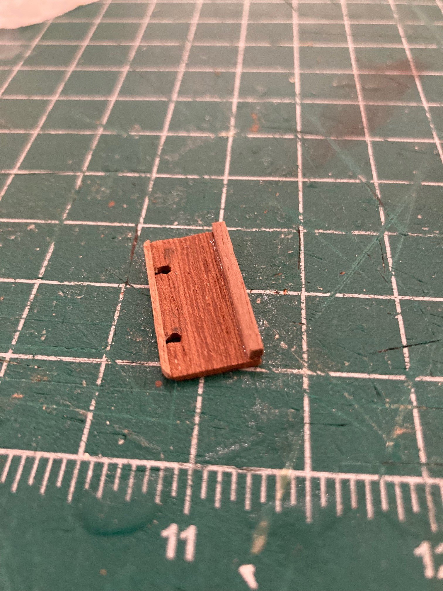
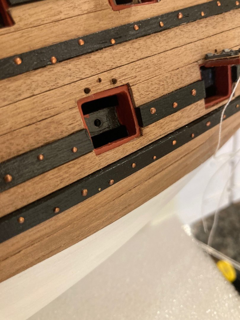
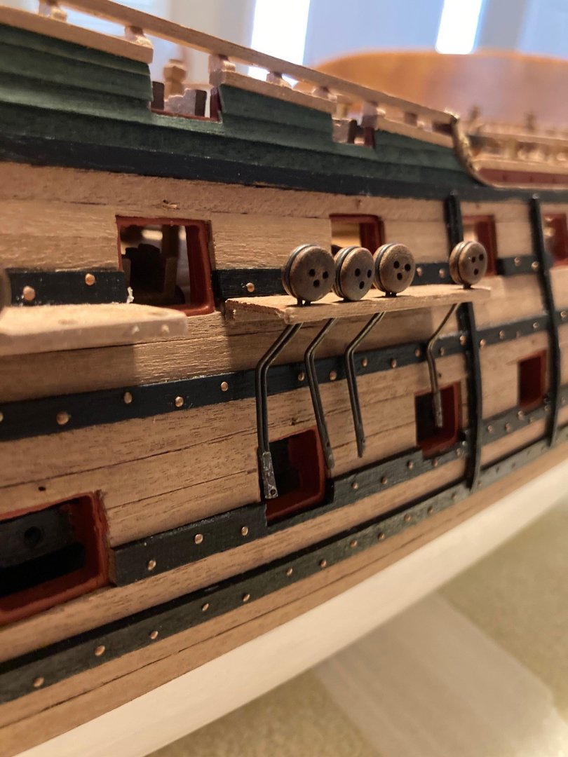
Started working on the gun port doors and getting them attached to the hull... also not a fun job. From the first picture (the two protrusion or ends of the hinge) were fitted in two small holes that I drilled just above each gun port (not pictured), gluing in with CA glue and and was able to achieve a solid attachment as a result. The instructions referenced to keep the port doors at a further angle upwards, but not sure how that would be possible and would not feel comfortable in getting a tight bond with the port and hinges to the hull. The last picture references my collection of gun port doors that are of a larger size and attach to the bottom row of the two on each side of the hull


-
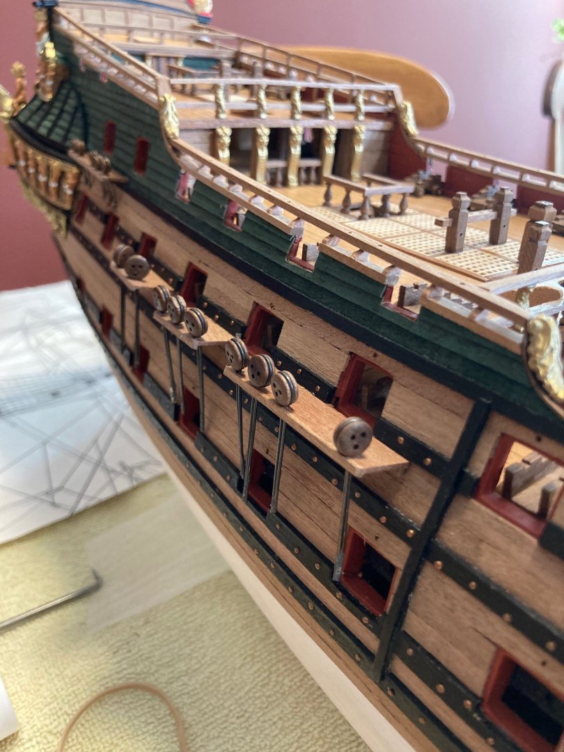
Finished the chainplates... not a fun job as once I cut back the extra chainplate length (in order to anchor on the wale), the ends kept wanting to separate (given no more solder keeping them together). I should have taken the time to resolder the ends but that is a new skill to me and I did not want to bother with that... next time! Bit of a CA glue mess on the two chainplate ends in the second picture. I will touch that up with dull black paint.


-
Good luck in your journey! Its a big build... at least you have the newer kit from Dusek with laser cut pieces and the fit will certainly be better than my old vintage kit from Mamoli where everything was cut with a scroll saw.
- 5 replies
-
- 2
-

-
- West Friesland
- Mamoli
- (and 11 more)
-
Look great! What project are you going to tackle next?
-
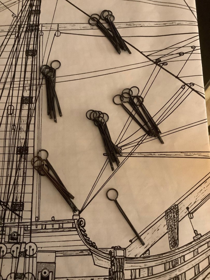
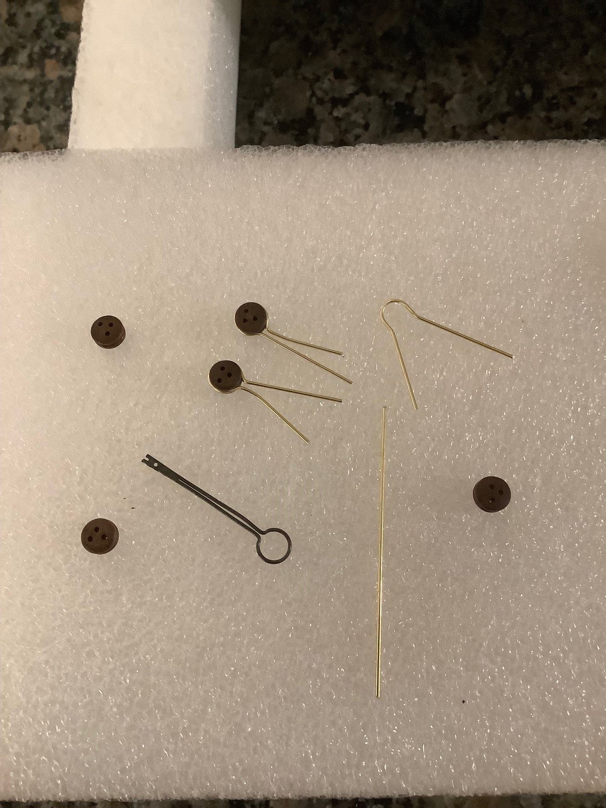
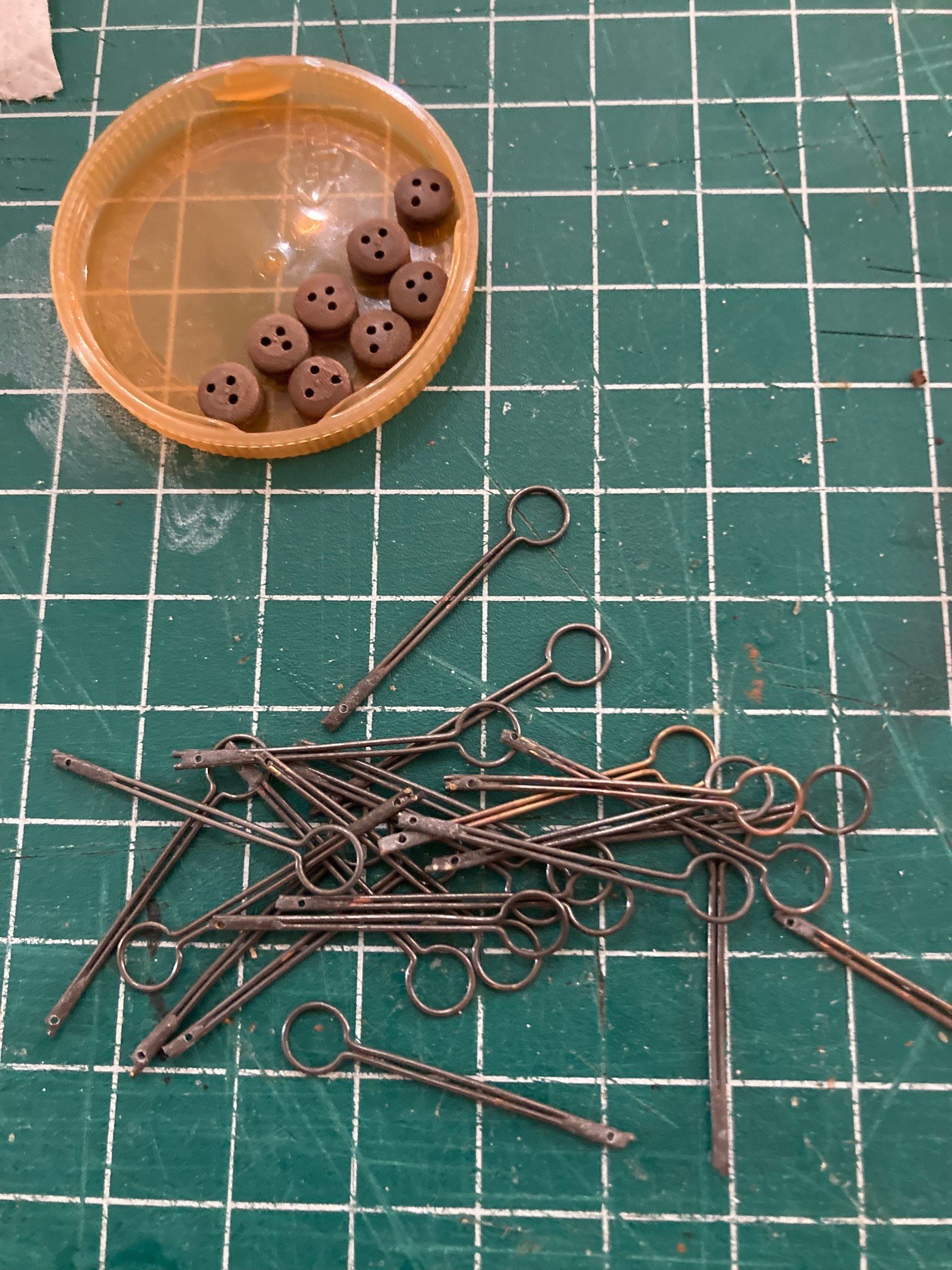
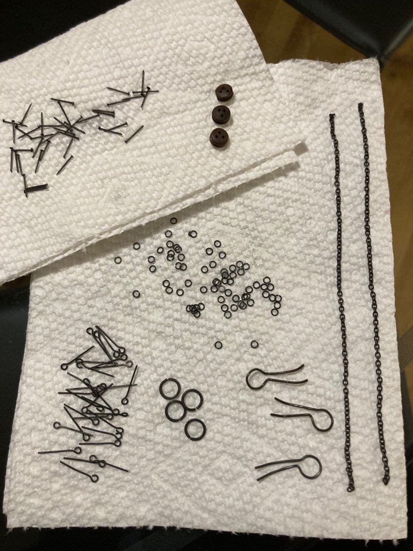
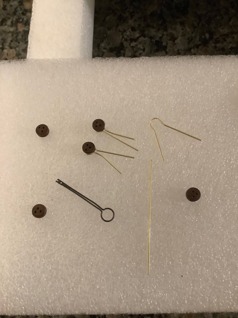
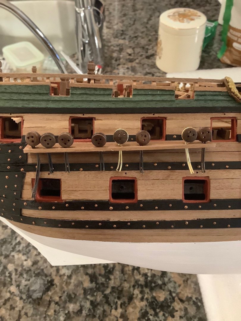
Last post today: did some blackening - the pins were copper alloy, rings and eyelets were brass alloys, the chain was super tarnished brass, and the new chainplates that I made being brass wire. My technique was the same for all - swished around in isopropyl alcohol for 5 minutes occasionally brushing with an old toothbrush, then rinse in distilled water, then transferred to household vinegar for 2 minutes, and then rinsed in distilled water, and then transferred into a 1:3 solution of 1 part Birchwood Casey blackening solution with 3 parts warmed distilled water, with a final rinse with distilled water and drying. The process was really quick - just 5-10 seconds in the blackening solution with the results shown below. Very happy with the results!
-
Some work on the chainplates; some bending, some twisting, some manufacturing (the kit was short 3 chainplates) from brass wire, and some cutting.

-
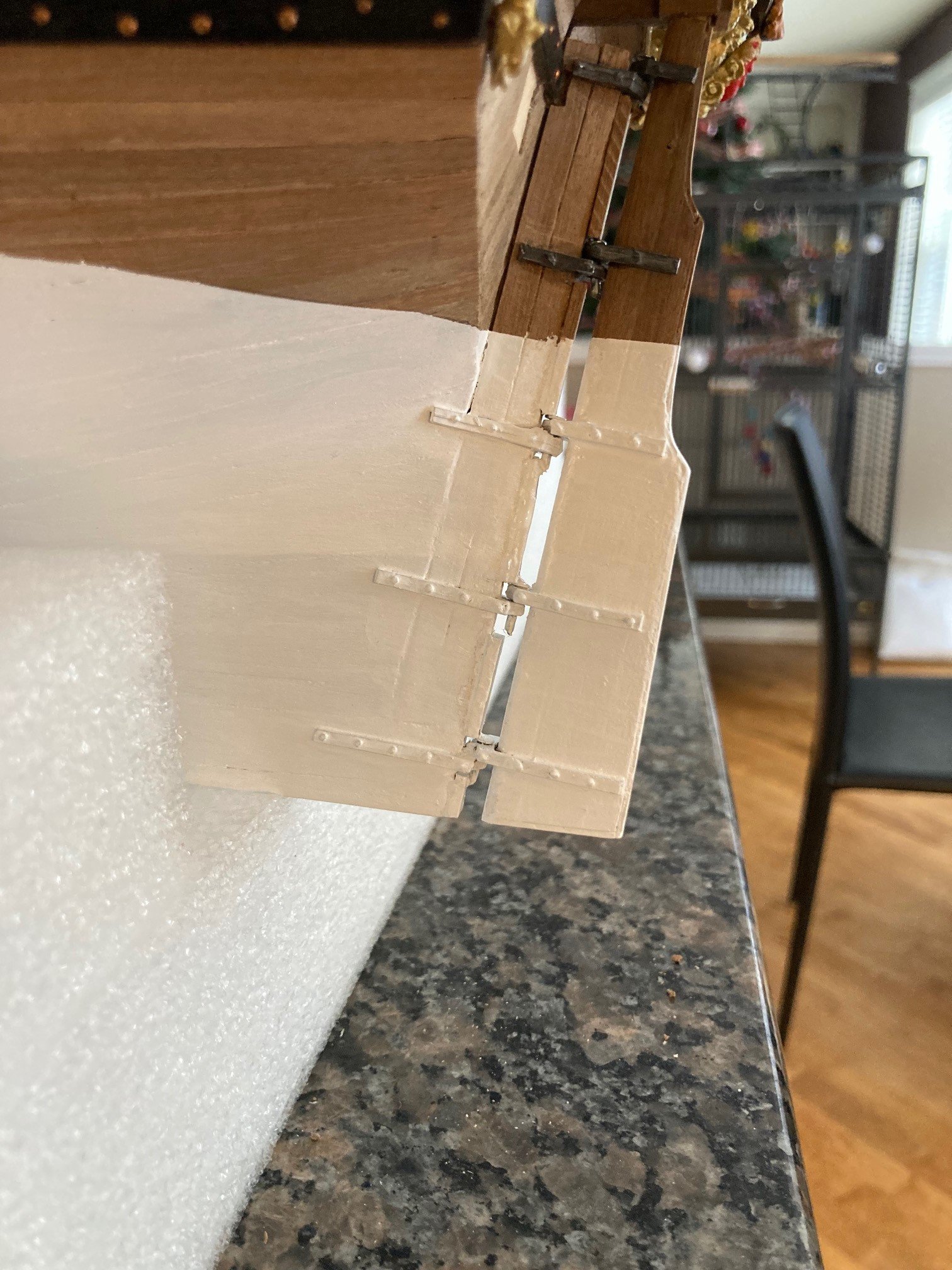
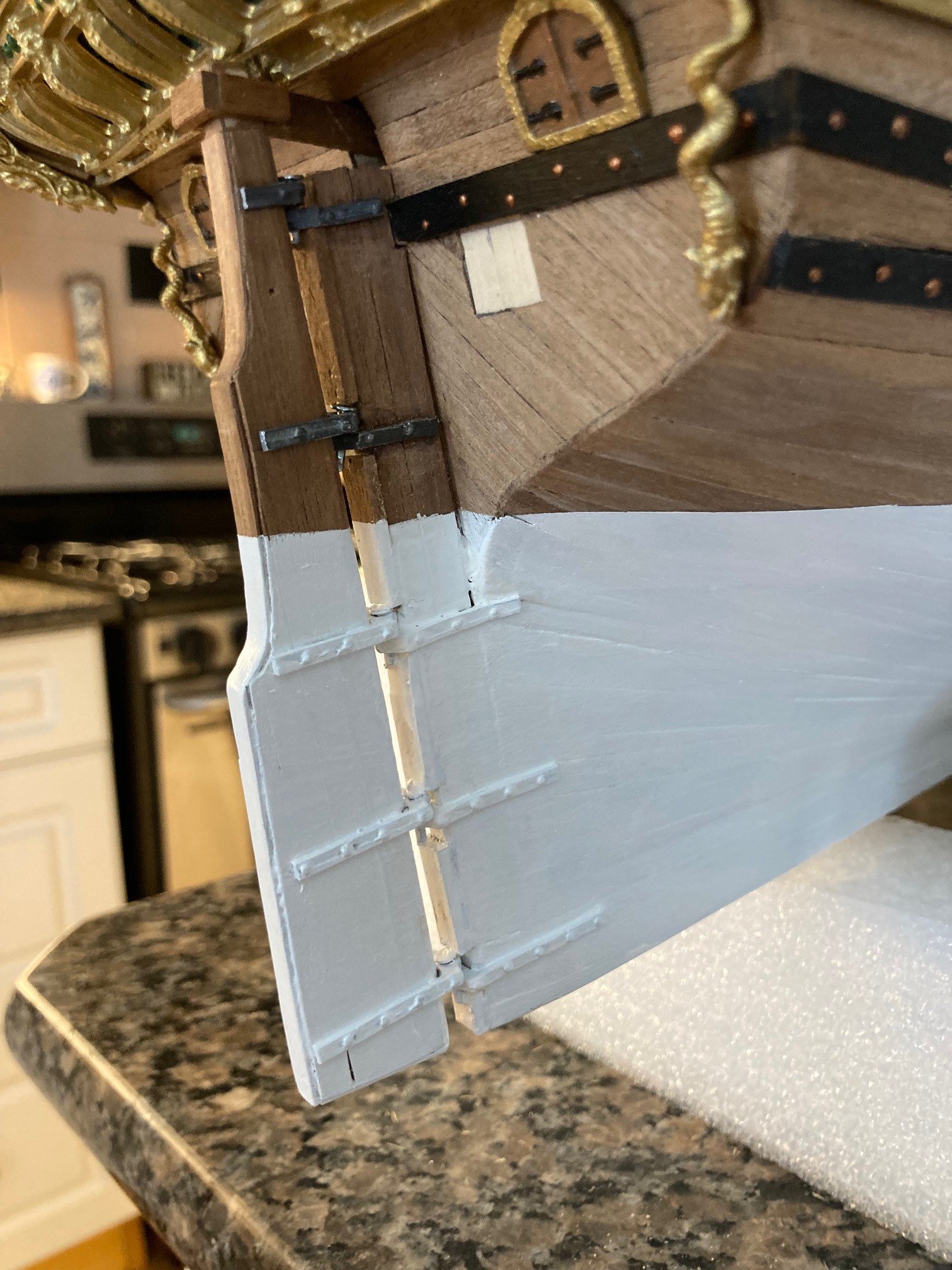
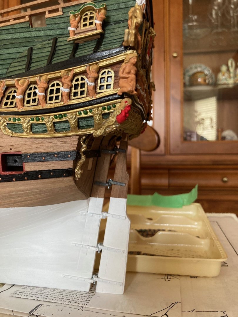
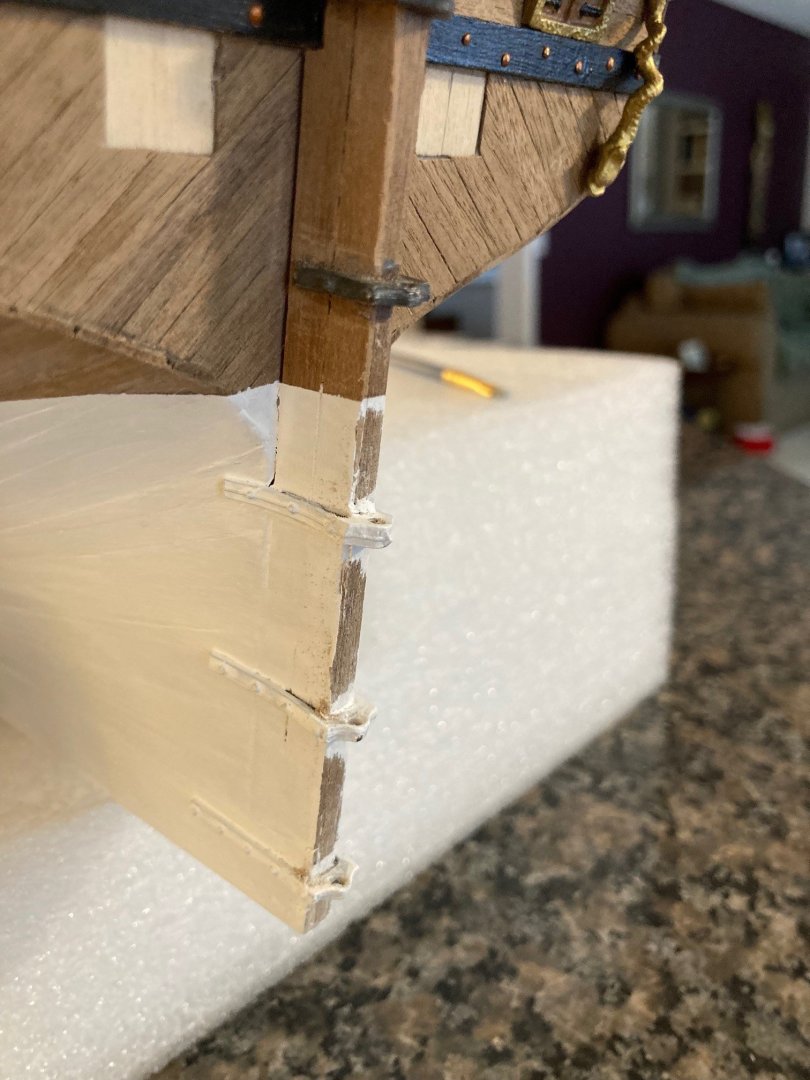
Update: Not happy with the space between the stern stem and the rudder. The space seems very excessive per the plans... I took off the rudder and put a fill piece in. Ideally I should have put it on the rudder side but the rudder margin length is convex and the stern stem is flat thus better accommodating the fill piece. Looks OK from up close but from 1 foot away, the fill piece completely blends in and is not noticeable. I think it looks better...


-
Thanks Jose for checking out my build log. I hope it provides lots of help in your journey building the Mamoli Santa Maria. The kit has some flaws but overall it builds into an excellent model. Cheers!
-
Thanks Patrick… I appreciate the images. I will be following the way depicted in the first set of pictures you listed from the museum. Yes, I believe, the most historically accurate.
-
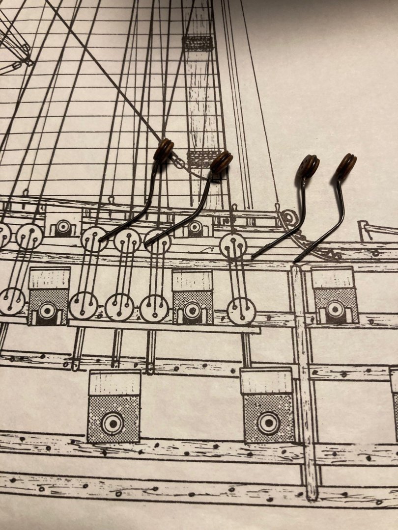
Starting some work on the channels, chainplates, and deadeyes. I added a 2x2 mm backing on the channels in order to get a better gluing surface to the hull. Also, the chainplates included in the kit are unfortunately short by 3 in number and they are definitively too long (per the plans) as I believe they should affix to the black strake immediately below the channel and not the hull. Noticed some variation of their attachments on both the dutch websites as well on MSW. I think it looks cleaner attaching to the black strake. Anyone have some suggestions?