
Jack12477
-
Posts
5,674 -
Joined
-
Last visited
Content Type
Profiles
Forums
Gallery
Events
Everything posted by Jack12477
-

DN Iceboat by MikeR - FINISHED
Jack12477 replied to MikeR's topic in - Build logs for subjects built 1901 - Present Day
Mike, good to see another ice boat build. Pulling up a seat to follow along -
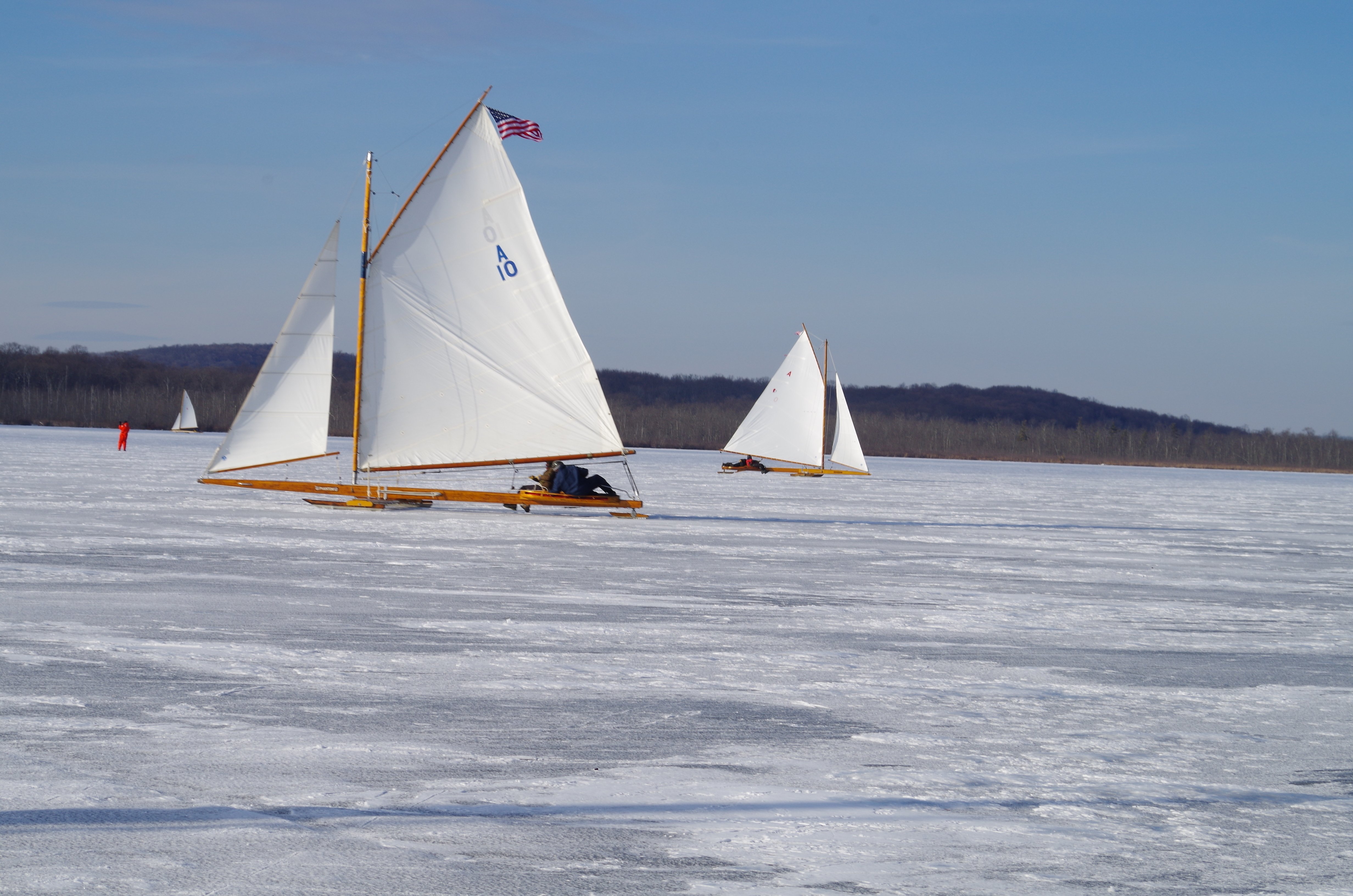
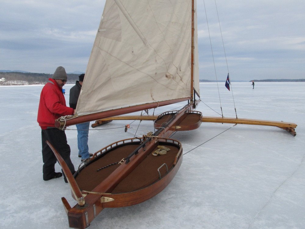
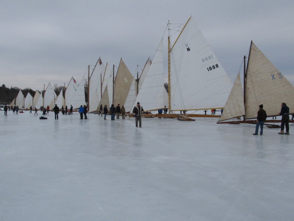
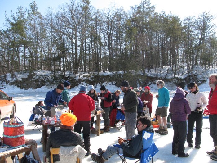
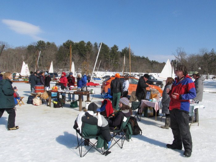
Hi Mark, I don't have any first hand experience manning the tiller but from my observations riding on the ice boats there does not seem to be any significant vibration or kick, except if you go over a hummock, pressure ridge or open crack in the ice, then you really feel it - quite a jolt. But the tiller runner (as well as the fore runners under the runner plank) is designed to pivot vertically on a 1 inch diameter bolt that goes thru the chocks and runner, in addition the tiller runner has a fairly large rubber shock absorber between the runner and the backbone. So, normally the ride is smooth even over mildly rough ice (runner plank absorbs some of the roughness) Yes, except for the fact that there is no hull per se, the rigging is pretty much like any other sail vessel. Almost all of the boats in our club are gaff rigged; we do have one Lateen rigged and one Marconi rigged. Regarding the apparent wind, according to some articles I've read on the science behind why these boats go so fast, (in the simplest terms) the true wind pushes on the sail causing the boat to move forward and the sail to take the shape (form) of an airfoil (airplane wing); the apparent wind passing over the sail (airfoil) causes lift which in turn pulls the boat forward. This coupled with the almost complete lack of drag (friction) is what propels these boats to such high speeds. That's the most simplistic explanation - the science is a bit more complex. And the rules of navigation around other boats is similar also. We refer to hulled boat sailors as "wet water sailors", while we refer to ourselves as "hard water sailors". Yes it is a blast to sail on them. COLD but a blast. Here's a few more photos unrelated to the Rocket: The "Fleet" gathered on the Hudson River in March 2014 (boats from our club plus several other clubs in NJ, CT, RI, Long Island NY) Note the 2nd boat in from the right with the number 1888 on the sail - this is Rocket from NJ the one I'm modeling here. The tall boat (6th or 7th in from right) with the American Flag flying from the gaff is our (HRIYC) class 1 boat (50 ft) Jack Frost. This is only a small fraction of the total boats still sailing. The Cold Wave with her double cockpit ( don't remember what club she belongs to or who owns her) And the traditional "pot-luck feast" on the ice.

- 110 replies
-
- 13
-

-
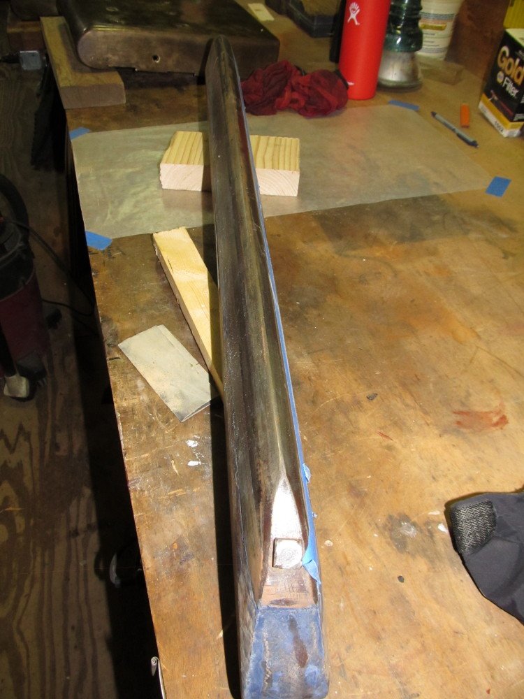
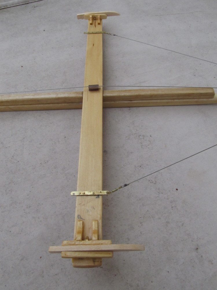
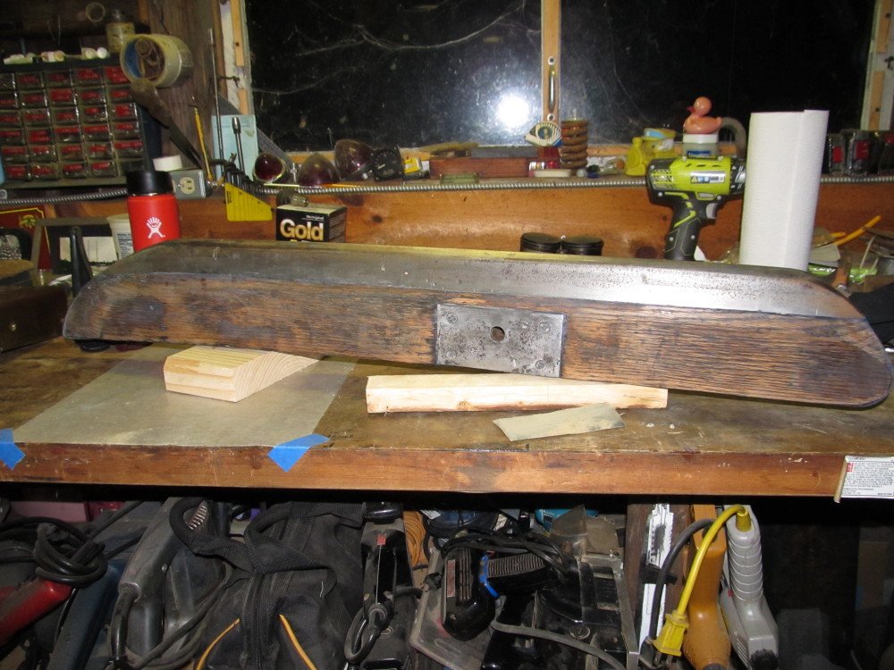
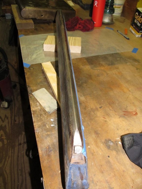
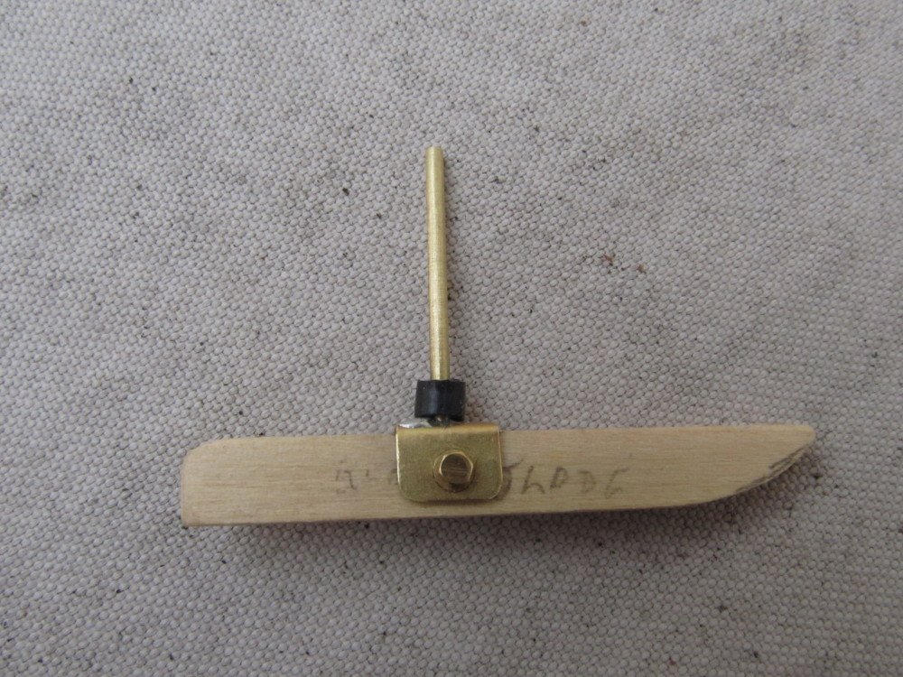
Hi Mark, yes I have to ask the guys in the NJ club how that boom sheet works. I have seen it under sail and I know the guys are working up a sweat controlling the boom. If by skids, you mean the "runners"; the upper part is quartered white oak 4 1/4 inches high at center by 2 1/2 inches wide by (on this boat) 5 feet in length, the part that contacts the ice is a soft cast iron skate/shoe sharpened at a 45 degree angle on both sides(cutting edge) with a depth of 2 3/4 inches. This cast iron shoe is fastened into the wood runner with 4 - machine screws 1/2 inch in diameter. The stern (steering) runner is the same dimension except slightly shorter in length. This boat (Rocket) has two sets of fore runners - a 5 ft and 7 ft long set. Since this is a 50 ft boat the runners are much longer than on a smaller boat but the runner is the same overall dimension except for length. The shortest fore runner is about 4 feet in length. And they are heavy - at least 100 pounds (US) each. Update: Mark, here's a close-up of a typical runner blade. This is the stern runner off a smaller boat, Manhassett, which is undergoing restoration by our club (HRIYC). It's much smaller than the runners on the Rocket but is typical of their design.
-
Thanks Carl. For those not familiar - the ice boats shown in photos 1 & 2 are very similar to the style of Dutch craft brought to America in the early 1800s by the Dutch settlers who used them to sail the frozen waters of the Hudson River delivering goods and other cargo to the cities and towns along the river. These craft were later adapted by Americans to the craft I am modeling today. Note that the boat in Carl's photos is a flat boat sail boat set into/onto a "cradle" with ice "skates". This "cradle" became the basis for the Hudson River Ice Yacht designs, i.e., backbone and runner plank configured in the shape of a cross. The small ice boat(s) seen in photos 3, 5 6, 8 with the front steering (rudder in front - bow area) is a American DN Class - named for the Detroit News (paper) which in 1930 sponsored a design contest to create a easily transported (e.g., car roof top) ice boat. The DN is the boat that won that design competition; the boat is very popular here in the States and I guess has also made its way to Europe or at least the Netherlands, judging from Carl's photos. Thanks again Carl.
-
Thanks Kees ! Yes, we do love your Dutch contribution to American recreation Carl (@COG) would you post here in my build log those photos you sent me of the Dutch ice yachts you saw this past winter in Netherlands. I'm sure others would like to see the Dutch boats (along with the American DN car-topable small ice boat that somehow made its way to Netherlands)
-
Thanks, Dave. I did manage to get it re-soldered without destroying the mast. Yes, it is a very exhilarating experience, especially on the largest boat (like the Rocket I'm modeling). When the boat tacks, the sails luff, boat slows way down, once the turn is complete and the boom swings around and the sails catch the wind, the acceleration is unbelievable. A handful of our club members have sailed our club boat, the 50 ft Jack Frost, on Lake Winnipesaukee in New Hampshire at speeds between 80 - 95 MPH (could easily do 100 MPH) and tell me that is a scary but exhilarating experience; of course they had a 16 mile run down the lake on dead flat smooth ice.
-
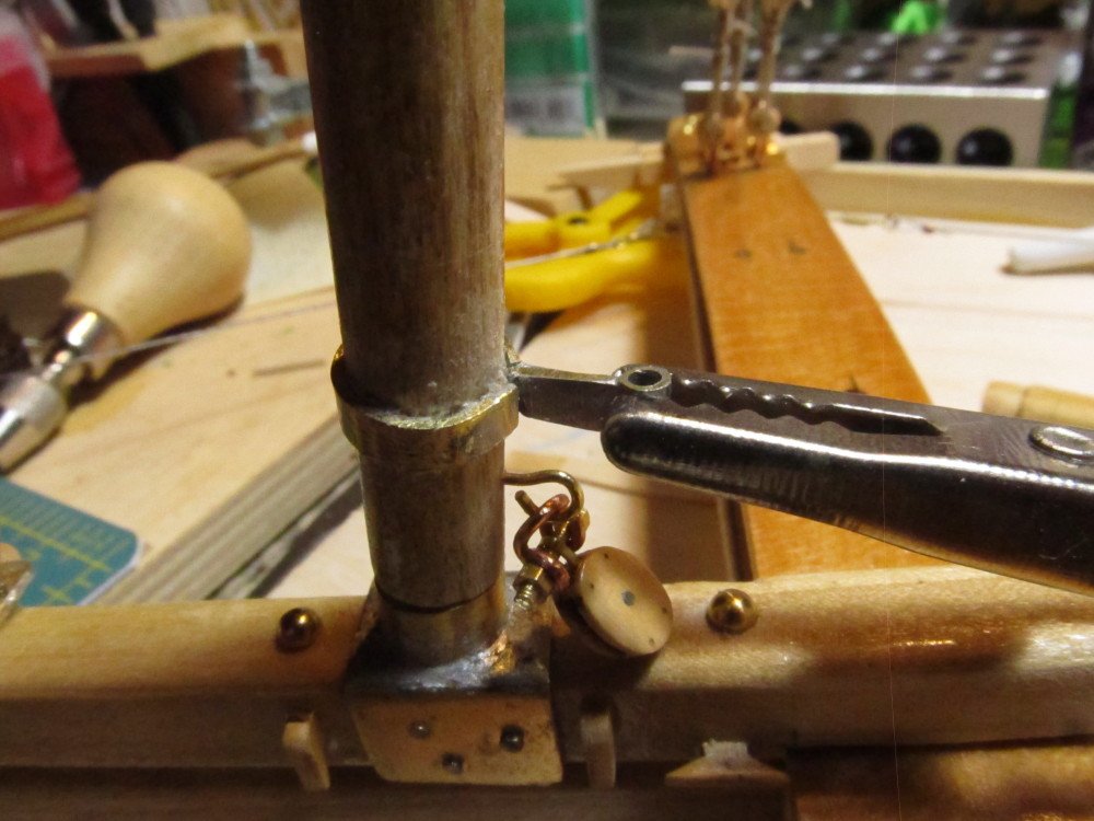
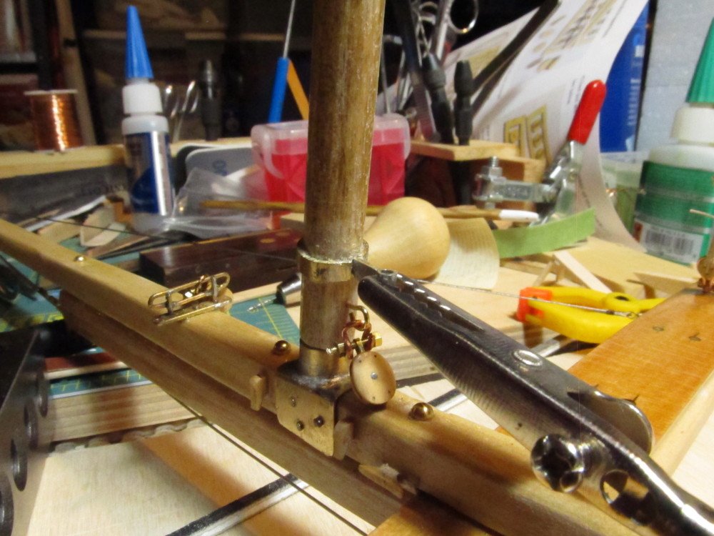
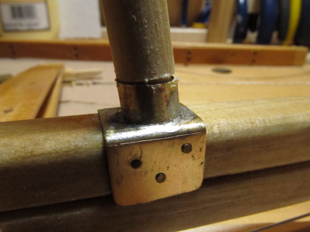
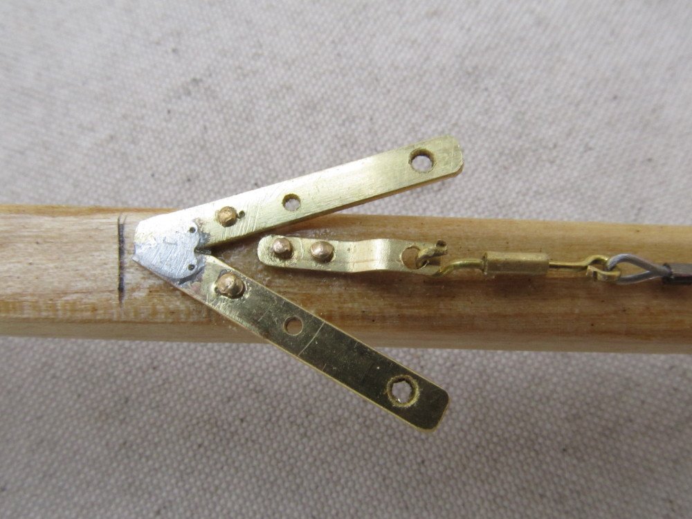
Thanks Denis. Yes there is a lot of rigging on these boats. Well, small (or maybe major) catastrophe last night after posting - I was tidying up the lines and blocks on the boom last night and somehow managed to snap the tab that holds the boom to the mast band off the band. The solder joint broke. Now I have to see if I can reattach it to the band without destroying the mast itself. If not then I have to completely disassemble the mast and make a new mast band. I did use silver solder when I made the mast band. The failed part is the piece held in the jaws of the alligator clip in the photos below. Two steps forward and then twenty steps backwards
-
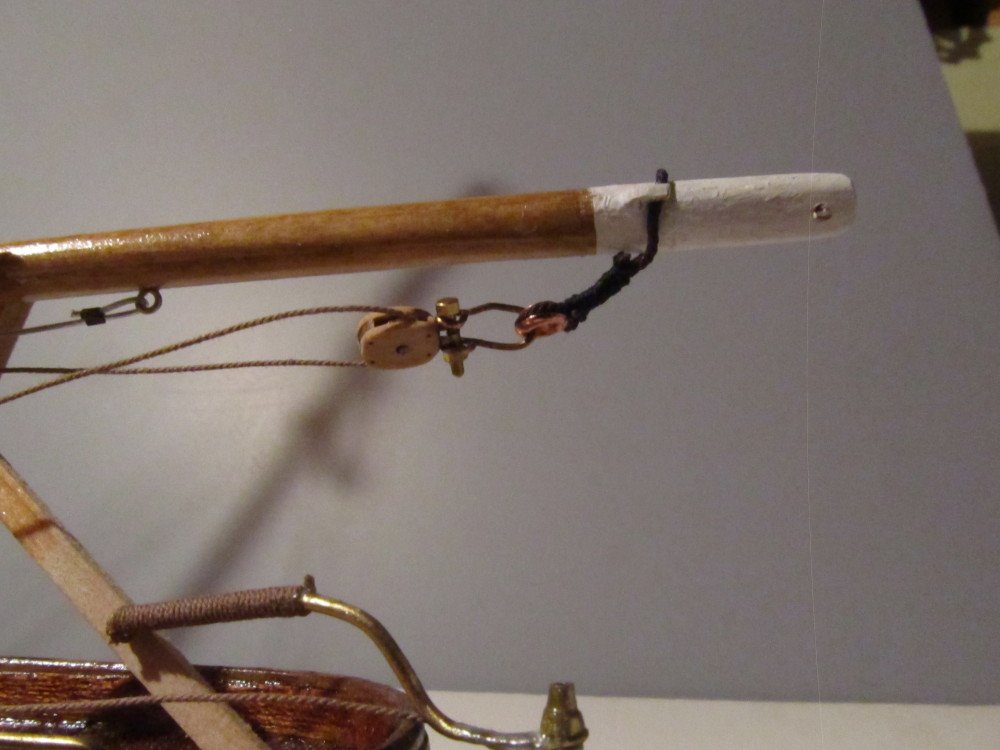
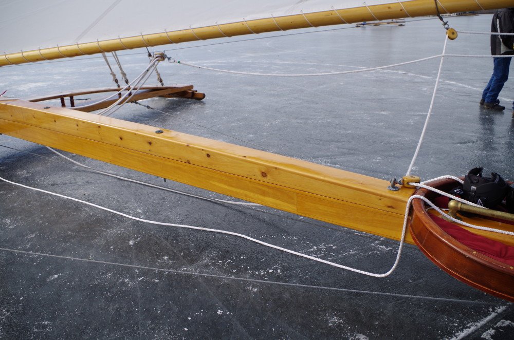
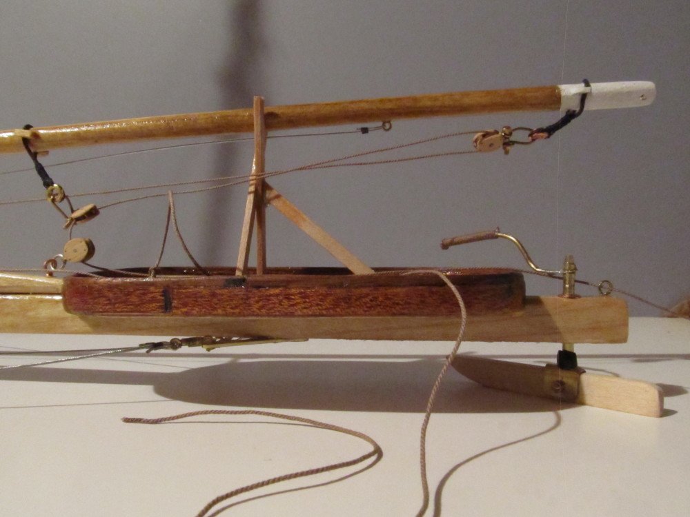
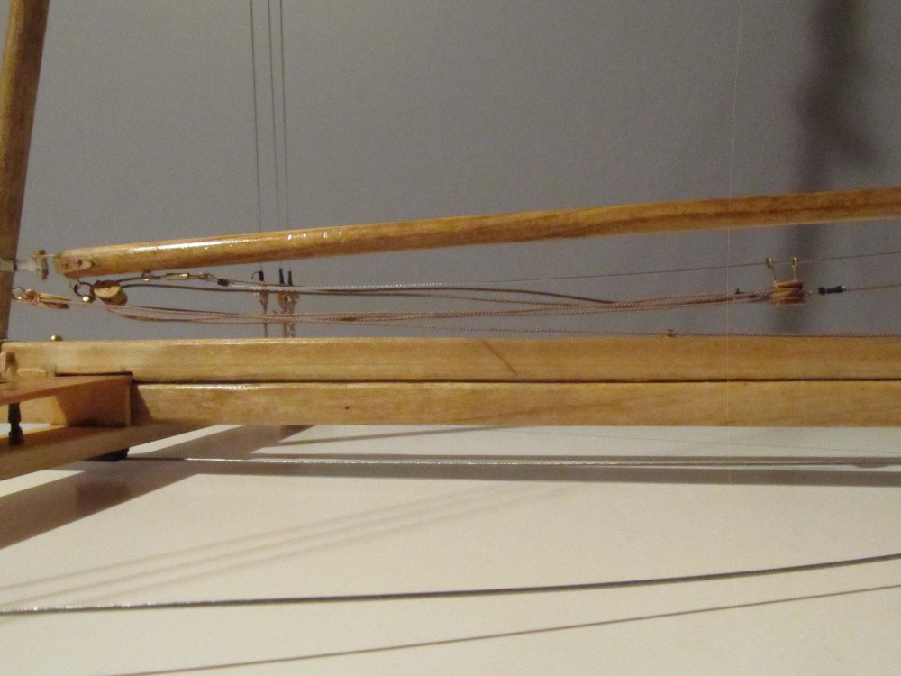
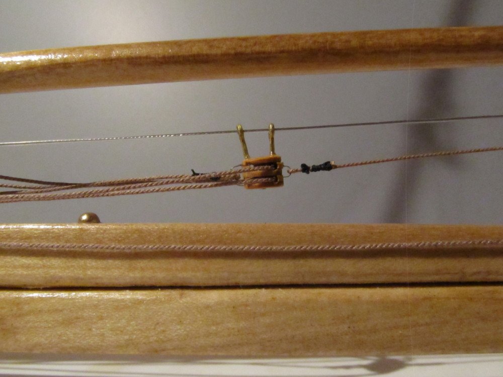
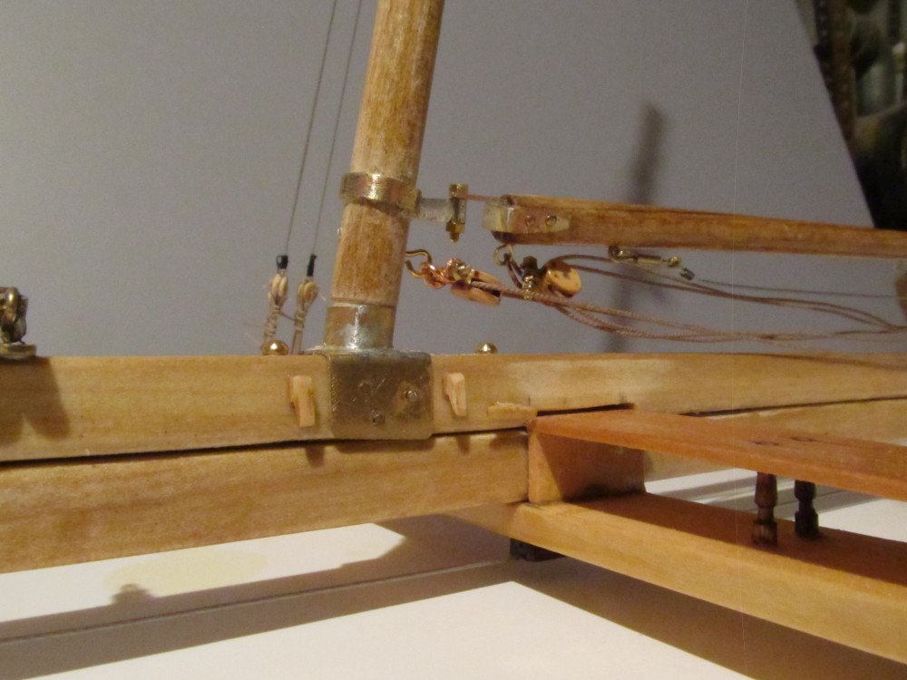
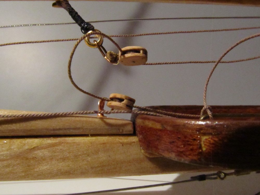
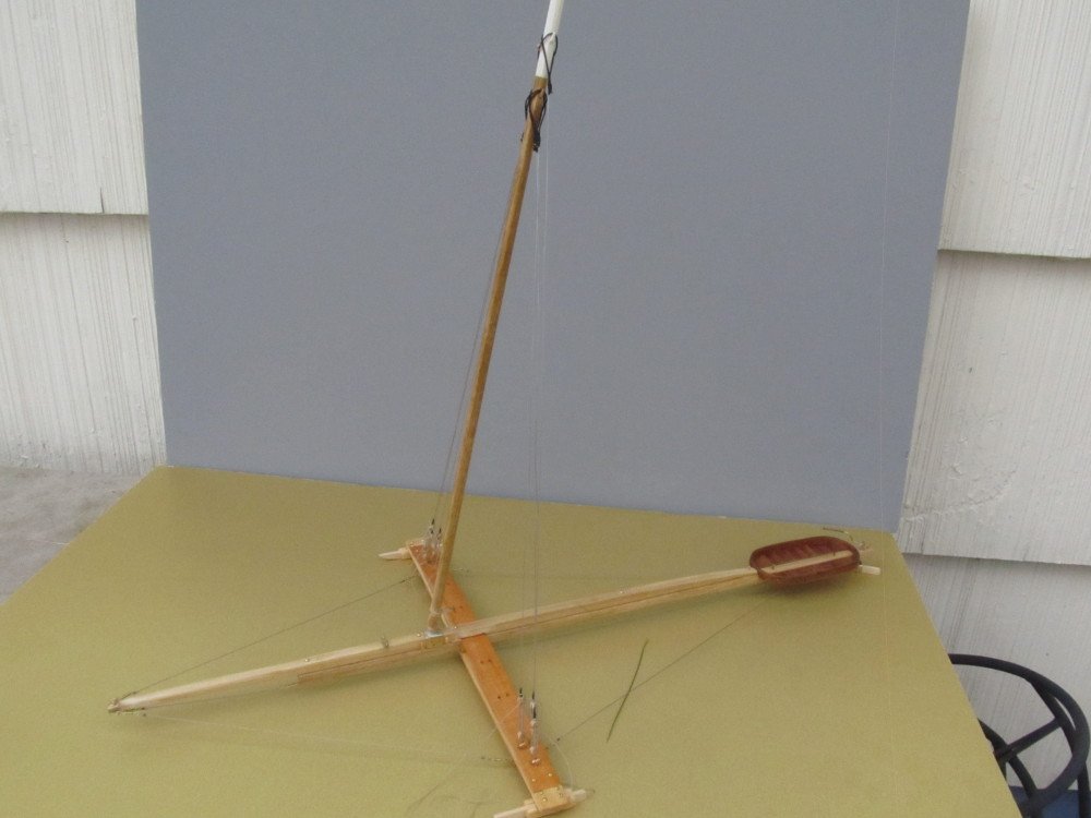
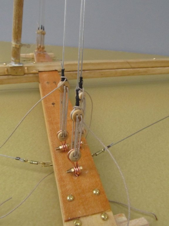
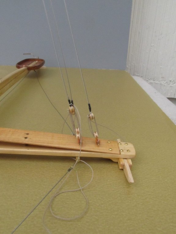
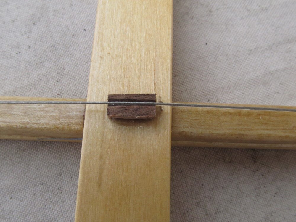
Well after several days of pouring over photographs, cropping sections, enlarging, printing, more cropping, more enlarging, more printing I finally figured out how the boom was rigged and more importantly how the double block traveler worked. The traveler rides along a steel cable strung underneath the boom end-to-end. At the stern end of the traveler a 3/8 inch line is attached which is fed back thru a single block at the extreme stern end of the boom back thru another single block affixed to the boom just in front of the cockpit then down thru a single block affixed to the backbone just in front of the basket. This is used to pull the traveler back towards the stern. Affixed to the mast side of the traveler is a 1/2 inch (or maybe 5/8 inch) line which runs thru a double block at the mast end of the boom back thru the traveler and back to the mast end block then finally thru a single block affixed to the mast below the boom. This line then leads back to the basket and is used to pulled the traveler forward. This combination is needed to control the boom under sail due to the massive weight of the sail plus boom plus the forces exerted by the wind. The shackles were constructed using 22 gauge bronze colored copper jewelry wire - tried making a jig to do this but that turned into a disaster, so I then tried doing it with a pair of rounded needle nose pliers, got passable results but a lot of discards (too big or too small). To fasten the shackles to the blocks I used 00-90 hex head bolts and nuts. To fasten the boom to the mast I used 0-80 hex bolt and nut. The blocks are Chuck's (Syren) 1/4 inch internally stropped single and double blocks, which I think look super - not hard to assemble, but you do have to pay careful attention while assembling them. Tried the ModelExpo tumbler but I think the 100 grit paper is way to coarse - nearly destroyed a couple of practice blocks - so I resorted to hand sanding them with some flexible, sponge ultra narrow sanding sticks I picked up in Hobby Lobby. To simulate the 1:1 rope I used Chuck's (Syren) 0.018 for the 3/8ths rope and 0.025 for the 1/2-5/8ths size. Photos follow: First the 1:1 photos showing traveler My implementation: Next step is to rig the gaff then install it. After that it's measure the dimensions of the main sail and have the Admiral sew a sail for me, then install it.
- 110 replies
-
- 11
-
-
Did anyone check the roof loading factor? With all those spectators swinging in bosun chairs ,!!!
- 1,090 replies
-
- 7
-
-
- showcase models
- vendetta
- (and 2 more)
-
Just a short update to let you all know I'm still here. No modeling for a while as I was in Sick Bay with a pollen induced sinus infection. When we went from winter to summer (i.e. 30 F to 92 F) in just over 2 days all the pollen suddenly burst out setting off my allergies again. But I have not been completely idle. I have been practicing (best way to describe it) making shackles from 20 ga copper wire; also pouring over photographs to try and determine how the rigging flows. Will post a few photos of my attempts in a few days.
-
Dan, be careful, red-white-red or black ball-diamond-ball (daytime), indicates vessel is not able to maneuver. USCG bouy tenders use this pattern when servicing a navigational aid (bouy). See Pat's chart, right side, 2nd panel down. ANT 101 (Aid to Navigation Team). Didn't recognize the light pattern at first, only the daytime pattern since our local ANT crew doesn't usually work on bouys after dark.
- 287 replies
-
- 6
-
-
- michelangelo
- ocean liner
- (and 1 more)
-
Dan, I agree with Druxey on the mast lights red over green would confuse any mariner. Can you get/borrow a copy of the "Nav Rules" from Kings Point or USCG ? The book describes all the lights both on ships as well as nav bouys. Remember " red right returning" !
- 287 replies
-
- 3
-
-
- michelangelo
- ocean liner
- (and 1 more)
-
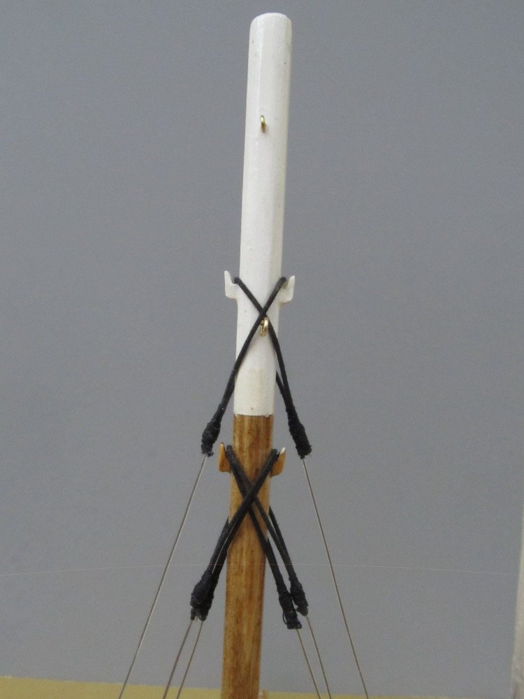
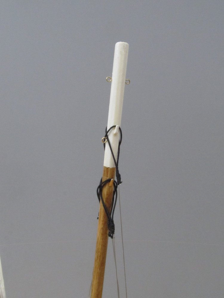
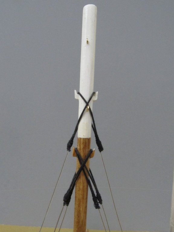
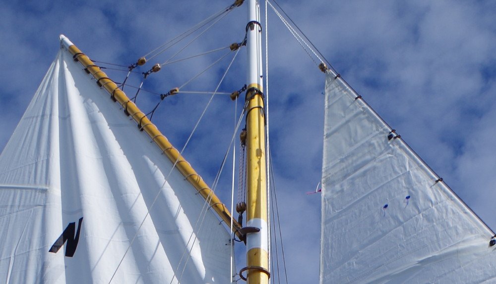
I temporarily installed the mast and upper and lower shrouds to make sure they fit correctly. The shrouds were made from jewelry bead stringing wire seized with standard black sewing thread. Photos follow. My next challenge is to figure out how to do the lift cable that support the gaff, they are placed 13 inches apart and 15 inches down from the tip of the gaff. The last photo below is a blow up of the actual gaff. Blow-up of the actual gaff, showing the lift cables.


- 110 replies
-
- 11
-
-
Machining copper stock.
Jack12477 replied to mtaylor's topic in Modeling tools and Workshop Equipment
Lard - I remember as a kid my Mom collected ALL the meat fat in empty metal coffee cans then put them once a week on the front porch stoop for some guy in a truck to collect the "lard" so they could make soap, lard, grease, and other things for the war effort - that's WW II - yes, I am that old. -
Over the last few days I made the shackles for the lower dead-eyes for the shrouds attached them to the eyebolts in the the runner plank with 0-80 x 1/4 inch hex head bolts and nuts. And YES they were a PITA to get those tiny nuts threaded onto the bolts. Also added the screws to secure the chocks to the plank. The shackles were made from 20 gauge copper wire.


- 110 replies
-
- 11
-
-
Billing Boats Marie Jeanne vs. Artesania Latina Marie Jeanne
Jack12477 replied to Redshirt's topic in Wood ship model kits
If you mean the Marie Jeanne Denis, you did follow me. Remember we changed the home port from France to Ireland and made new decals (with your advice) to put the Coat of Arms on the sail..... I have a new log you can follow - an ice boat/yacht from 1888. -
Billing Boats Marie Jeanne vs. Artesania Latina Marie Jeanne
Jack12477 replied to Redshirt's topic in Wood ship model kits
I have not seen the Billings kit so I can't comment on it, but I have built the AL Marie Jeanne kit (see signature for link to build log) and had no issues with the kit. Wood was first class, Denis points out the sail are pre-made with a nice bolt-rope sewn on, metal parts were good - no flash to remove. Instructions were about as good as all other kits by any manufacturer. I had fun building the AL kit and the model came out pretty good. -
How are Ice Yachts Measured and Classified? The Classification is by sail area. In the early 1900's a gentleman named H. Percy Ashley wrote a series of articles for Rudder Magazine documenting the ice yachts of his day, including several articles titled "How to Build an Ice Yacht"; in these articles (which I've been using as reference material) he describes two different but very similar Classification systems (which are still used today). The first system he describes divides them into 4 classes. Class 1 - measuring 600 square feet of sail area and over; Class 2 - measuring 450 square feet of sail area and under 600 square feet; Class 3 - measuring 300 square feet of sail area and under 450 square feet; Class 4 - measuring less than 300 square feet of sail area. Boats in each class display the class number on their sail. In the second system he describes the classification and letter carried on their sails as follows: Class A - measuring 600 square feet of sail area and over; Class B - measuring 450 square feet of sail area; Class C - measuring 400 square feet of sail area; Class D - measuring 350 square feet of sail area; Class E - measuring 300 square feet of sail area; Class F - measuring 250 square feet of sail area; Class G - measuring 200 square feet and below. Boats in each class display the class letter on their sail. Both of these classifications were in effect in 1913. I do not know why there are two different but very similar systems. Most people today use the classifications interchangeably. The Rocket and the Jack Frost are both Class 1 (or Class A) boats with over 900 square feet of sail area each.
-
I use medium CA - gap filling - (15-20 second cure time) - holds pretty well for me.
-
Frank, that's what I did with my Willie Bennett skipjack - see here Great job on the railings on your boat. Been following along silently and learning a lot from your narrative.
-
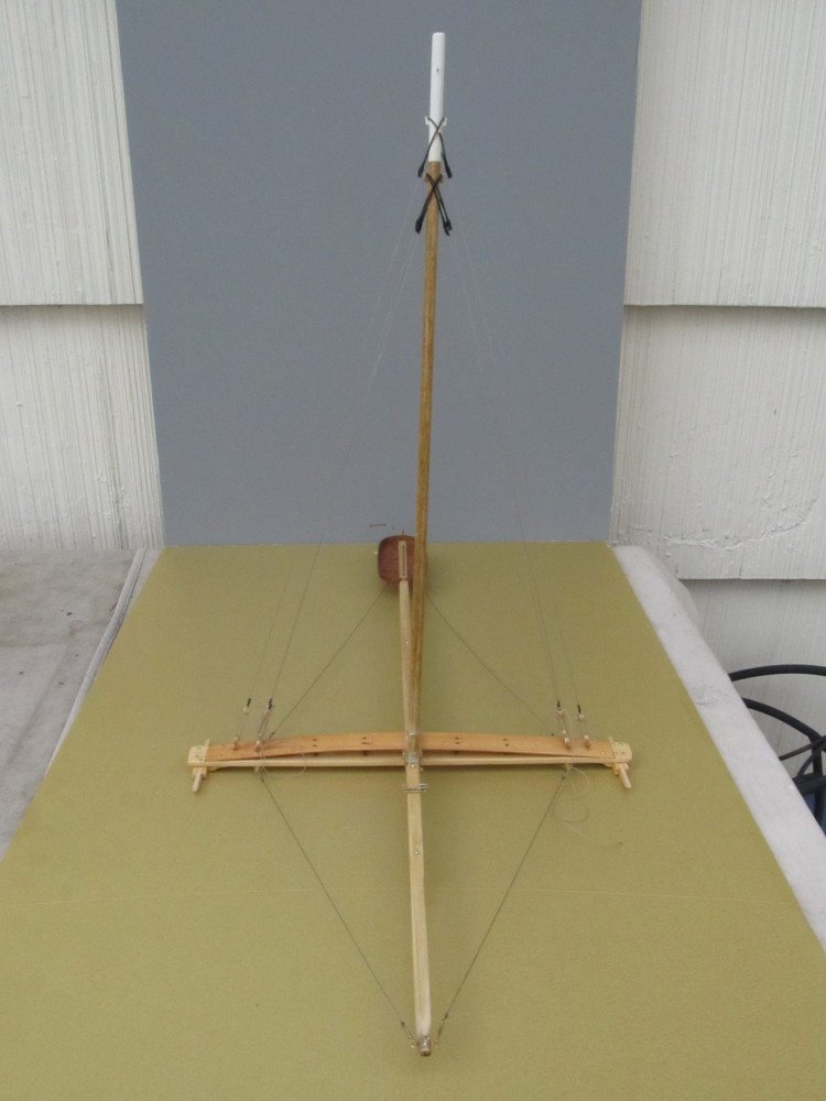
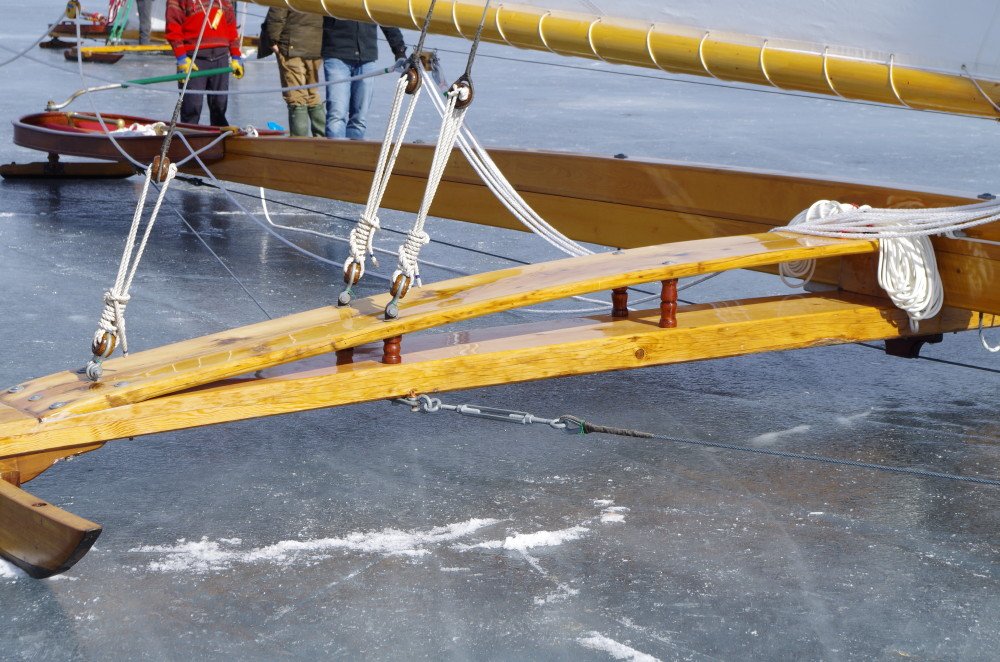
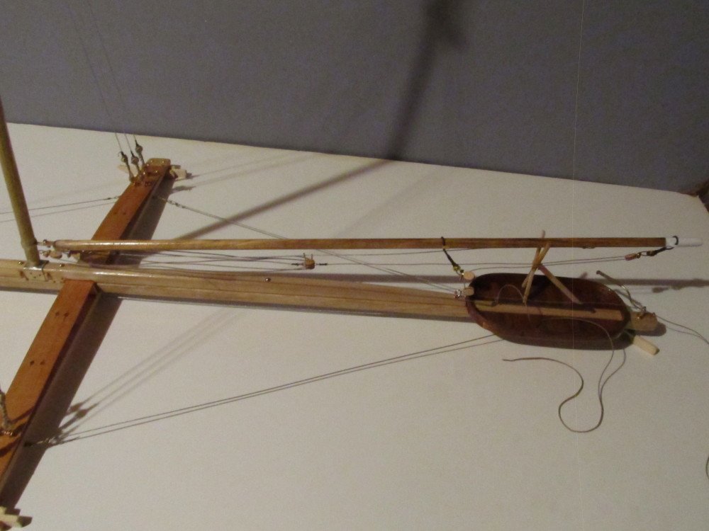
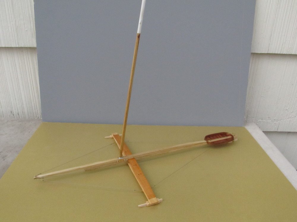
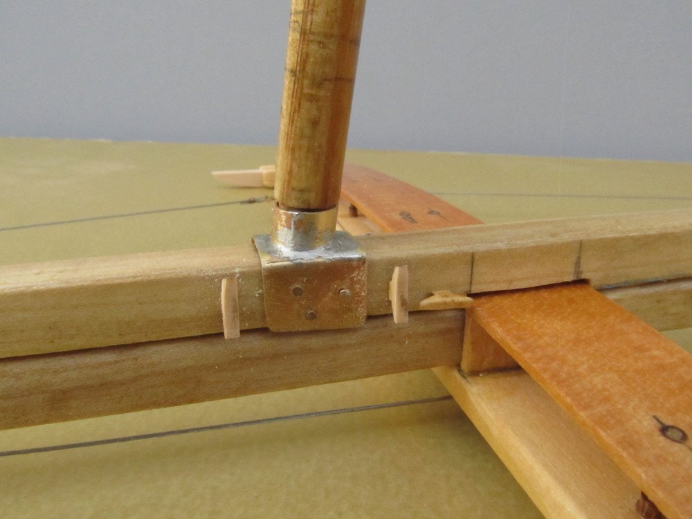
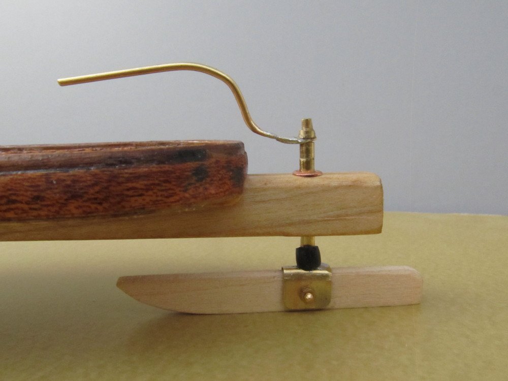
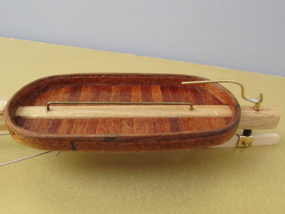
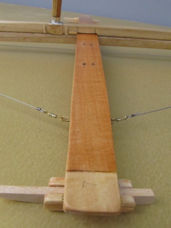
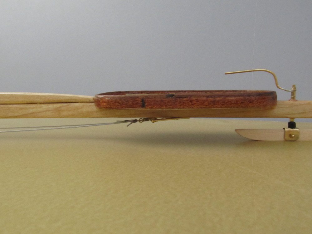
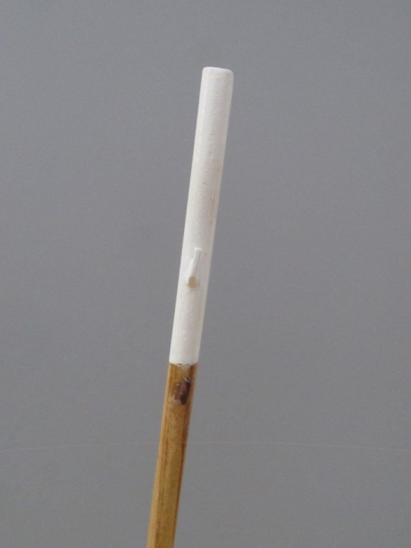
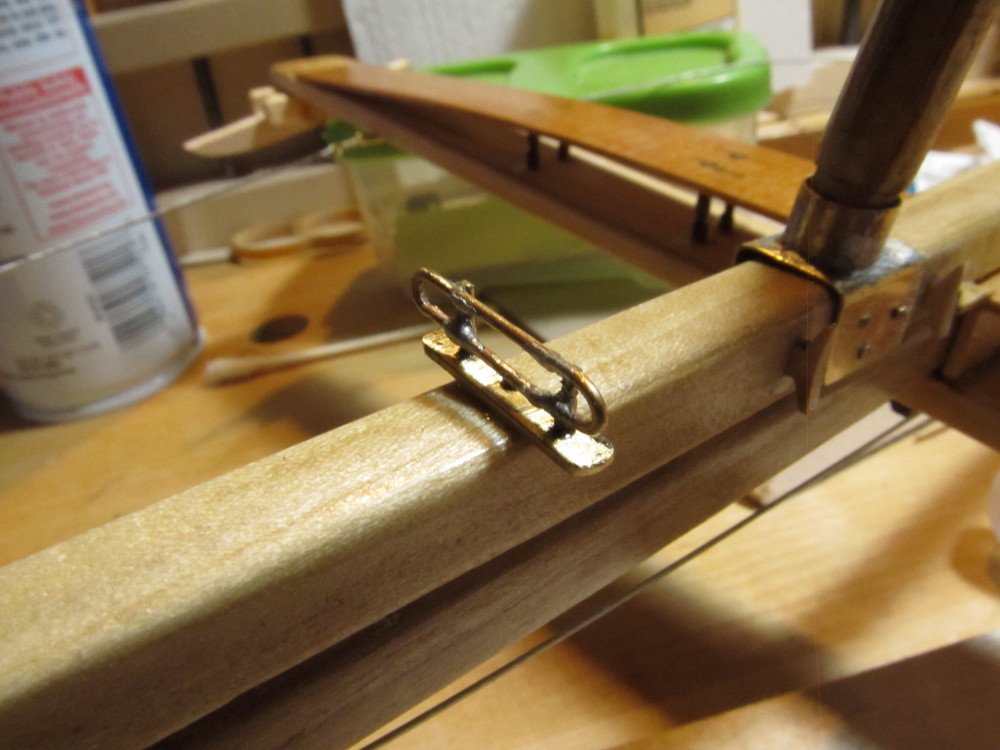
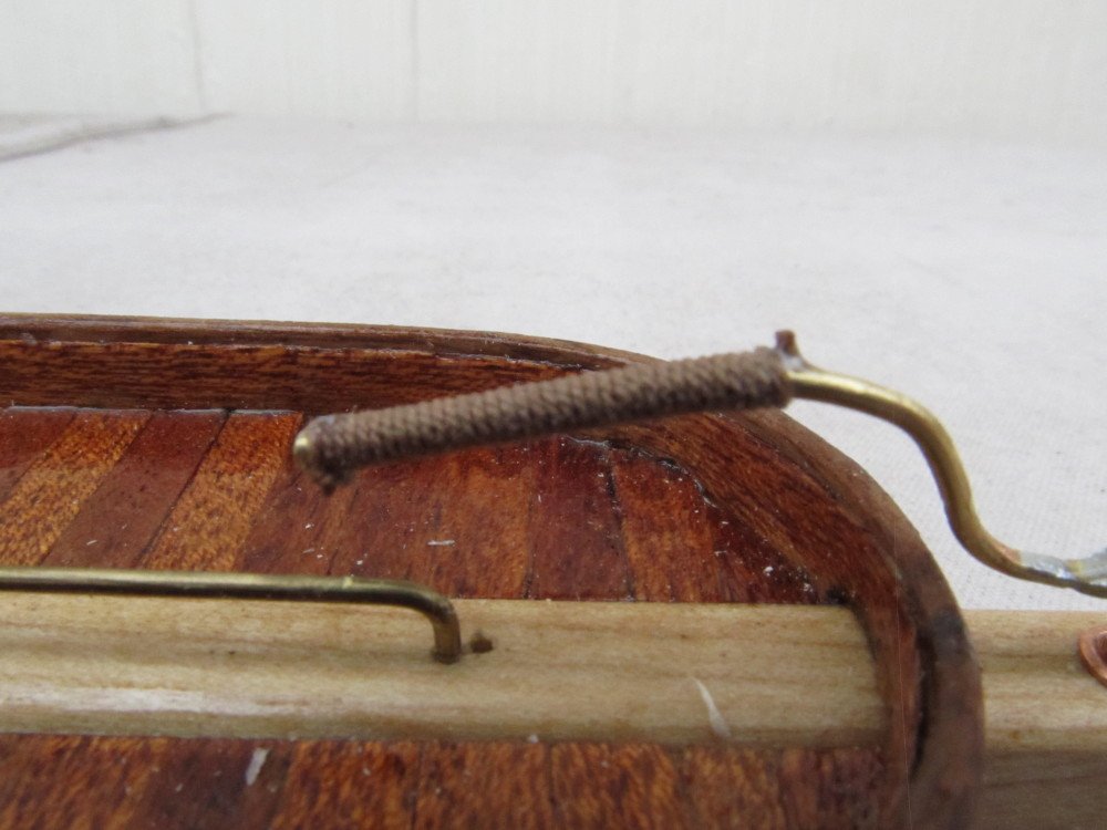
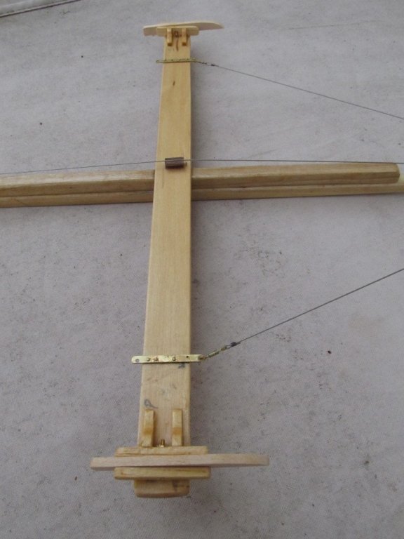
Moving on, I've assembled the boat, attached all the guy wires to the backbone/runner plank. Installed the mast step, and jib traveler, installed the tiller and it is functional - it does turn. Started working on the mast. Installed the 1st four "cleats" for the shrouds, painted the upper section white, rest is stained Golden Oak and covered with high gloss poly. Still more work to do on the mast. And need to construct the boom, jib club foot and gaff. The mast is only press fit into the mast step for now so I can remove it and continue working on it off-boat. Our ice yacht club is having our end of season pot luck dinner this Saturday; I'm going to take the model with me and hope to get some feedback from the group, especially the members of the New Jersey club who actually own the boat I'm modeling. Progress photos follow: Overall photo of boat Mast step with Cleats Basket with "chicken bar", tiller and stern runner. Added the rope wrap to the tiller handle. (Sorry for the blurriness - camera won't focus any closer) Fore and aft stabilizer guy wires - prevents runner plank from racking and getting out of alignment with the backbone (perpendicular to backbone) Jib traveler
- 110 replies
-
- 12
-
-
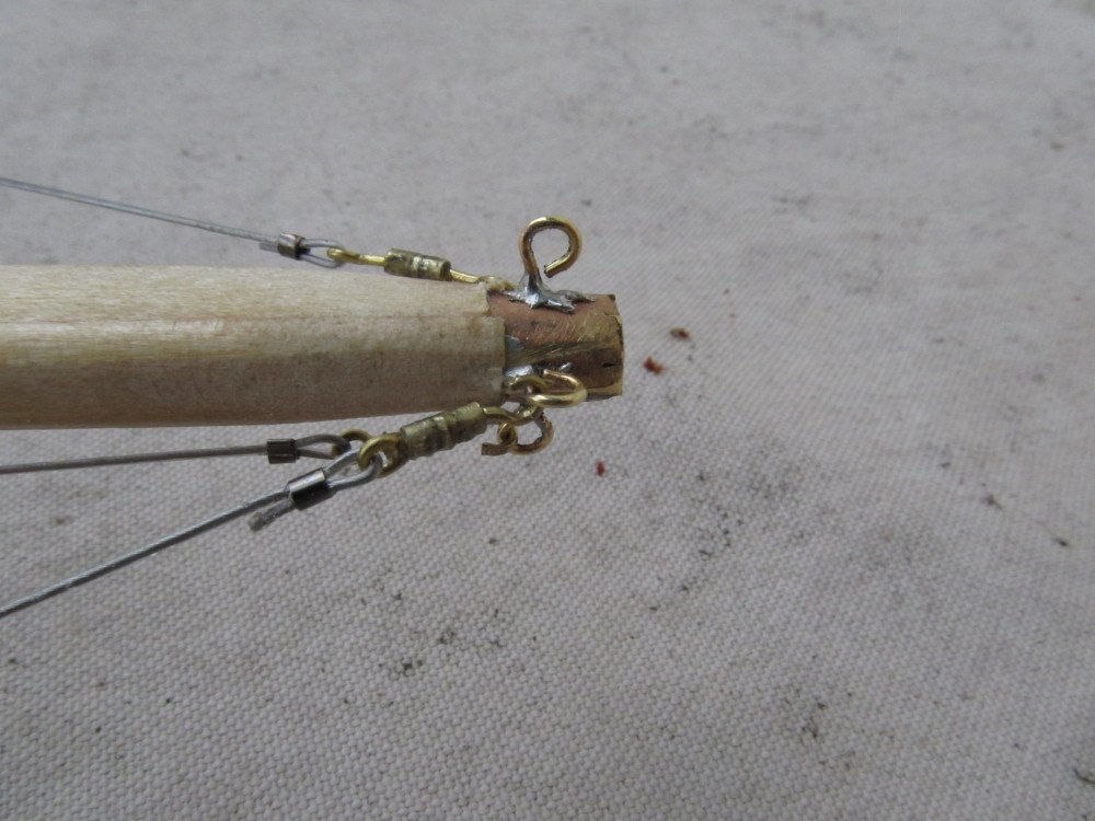
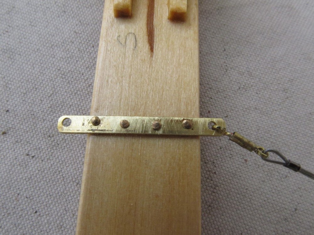
Small update: I completed the stern rudder. the o-ring suggested by John (Jhearl) worked great and looks convincing from a distance. I decided to glue the two halves of the backbone together including inserting the lower half thru the runner plank truss. To keep the runner plank in alignment guy wires are connected from the bow to each side of the runner plank approximately 3/4 of the length from the back bone; additional guy wires secure the runner plank to the stern. The longitudinal guy wire which runs under the backbone from bow to stern was also added. (The two guys wires running from the stern to aft edge of runner have yet to be installed).
- 110 replies
-
- 12
-
-
Yes and No ! The runner plank (cross plank) has a bow (curvature) in it starting at mid-section and running out to the runners on each side which allows quite a bit of flex in the plank which in turn smooths things quite out a bit. Think of the old leaf springs that used to be on the rear axle of cars, sort of the same principle, except it's at right angles to the backbone (keel) which allows each runner to independently flex upward. In addition the stern rudder has a rubber bushing to absorb some shock. But if you hit a section where the ice has cracked and lifted (ridge) you can get quite a jolt when the stern goes over it. The length of the runner (skate) also acts to cushion the ride and the skate will pivot vertically on the bolt. But generally speaking we try to avoid really rough ice and stick to place where the sun and other elements have worked to smooth the surface. Replacing a broken runner plank is not as easy as running down to the local lumber store and picking up a new plank. There's a lot of work that goes into making a new runner plank.