
Jack12477
-
Posts
5,674 -
Joined
-
Last visited
Content Type
Profiles
Forums
Gallery
Events
Everything posted by Jack12477
-
 It's the John W Brown - restored and displayed in Baltimore (MD) Inner Harbor - saw it couple years back when I took my granddaughter there to tour the USS Constellation and the submarine - submarine freaked her out but the Constellation fascinated her.
- 1,090 replies
-
- 4
-

-
- showcase models
- vendetta
- (and 2 more)
-
Okay, I placed the order with HobbyLinc for the Liberty ship and The Sullivans Fletcher class kit. Will let ya'll know when they arrive.....
- 1,090 replies
-
- 8
-
-
- showcase models
- vendetta
- (and 2 more)
-
Oops! You are right Lou, The Sullivans is a Fletcher Class. Should have looked at the Buffalo Navy Park site first before surfing HobbyLinc's website. Saves me buying a duplicate kit, more $$$ I can spend on PE. Thanks, Carl, I use rattle can primer a lot, with demise of Floquil, I've pretty much switched to Tamiya and Vallejo brands. I'll use the air brush for the camo and other finer detail painting, easier to control coverage than rattle can. I'm going to go with the two ships I've actually seen. I'll drop the DD445 kit from list. Going to Buffalo this summer to see my granddaughter so maybe I can get her to tour the ships with me. Greg, looked up that Seydlitz kit on HobbyLinc. Man, I could buy all three of my ship kits for the price of that one kit!
- 1,090 replies
-
- 8
-
-
- showcase models
- vendetta
- (and 2 more)
-
Thanks Greg. Yes I tend to look for the "road less traveled" also and less expensive. The kits are available from HobbyLinc which is USA based so shipping is cheap and quick and I have dealt with them before so good experience there. Also found Alliance ModelWorks also USA based which has a fairly good looking selection of PE brass in 1:350 scale - saw some sheets for doors, hatches, railings that ran about $13 US a sheet plus shipping. So not too bad I think. Have to look at their web site a bit closer as I was just skimming it to get a ballpark feel for price/availability. I did a lot of 1:35 scale Tamiya tanks (WWII US and Europe) before I ventured into wood boat kits and I used an air brush for all the camo patterns (miss the Floquil paint tho) - also did some aircraft in camo. I'm a tad rusty but it will come back to me I'm sure. COG and I are old "buddies" on here so not a problem with his "bullying" - besides he's only a tad taller than me anyways. I'll let you know what I decide.
- 1,090 replies
-
- 9
-
-
- showcase models
- vendetta
- (and 2 more)
-
Okay, you guys have now piqued my interest in going back to plastic models for a slight diversion. I found 3 kits in 1:350 scale on HobbyLinc for a pretty decent discount. Two are by Trumpeter, USS The Sullivans DD-537 and the USS Liberty ship John W Brown; the other kit is by Tamiya US Navy Fletcher Class DD445. I picked The Sullivans and the Liberty ship because the Sullivans is on display in Buffalo's (NY) waterfront park and the John W Brown is on display in Baltimore's Inner Harbor; both of which I have seen up close and personal. The Fletcher is just an interesting ship. Opinions please ! Get all three or a combo ???? Or forget it ???? Pros ?? Cons ??
- 1,090 replies
-
- 6
-
-
- showcase models
- vendetta
- (and 2 more)
-
John, Keith, Tom, Scott, thank you for your condolences. It's been a rough couple of weeks. His funeral was last Friday. I'll be returning to the shipyard shortly.
-
Okay ! Make room ! I'm joining too Oh ! I'm already joined ! Hmm. okay time for munchies then


- 292 replies
-
- 7
-
-
- g class destroyer
- trumpeter
- (and 4 more)
-
I'll take 2 scoops, any flavor, with sprinkles please!
- 405 replies
-
- 7
-
-
- tamiya
- king george v
- (and 2 more)
-
DN Iceboat by MikeR - FINISHED
Jack12477 replied to MikeR's topic in - Build logs for subjects built 1901 - Present Day
Mike, what material did you use to make the sail? It looks like you made a slot in the mast and boom to slide the sail into. Is that what you did? -
Had a nun in 8th grade try to wack the back of my hand with a plastic ruler, at last second before contact, I clenched my fist tight and rotated it 90 degrees, ruler hit the thumb side of fist and shattered. man was she mad but never tried it on me again !
- 1,090 replies
-
- 6
-
-
- showcase models
- vendetta
- (and 2 more)
-
Ok, just rigged the bosun chair to the rafters to watch, Greg. Whose got the popcorn?
- 405 replies
-
- 7
-
-
- tamiya
- king george v
- (and 2 more)
-
OC, for filler I used to use Squadron green putty (also comes as white putty) worked well to smooth and fill in gaps on plastic. Don't know if it is available in UK, I even have trouble finding it in the "colonies" lately.
- 229 replies
-
- 6
-
-
- trafalger class
- airfix
- (and 2 more)
-
Requesting feedback for future MSW Group Projects
Jack12477 replied to Chuck's topic in Group Projects on Model Ship World
Al, when I did the furled sails on my Willie Bennett, I made the sails full size (scale full size), raised them to full height on mast, then slowly lowered them onto the boom folding them as I went (same way we fold the sails on the ice boats at end of day), then tied scale rope around them to secure them to the boom. Did the same with the jib and club foot. Furling a square rigged might be a little different, don't know. -
Thanks John. He passed away this morning at 6 AM Eastern time. Funeral arrangements haven't been finalized. He was 75.
-
DN Iceboat by MikeR - FINISHED
Jack12477 replied to MikeR's topic in - Build logs for subjects built 1901 - Present Day
Mike, WOW, that gun stock oil really makes the wood pop. Nice job. Great job on the sails and battens, as well as all the brass work. Now if we could just shrink ourselves down we could take her for a nice sail. Glad you joined me for something different in subject matter. -
Requesting feedback for future MSW Group Projects
Jack12477 replied to Chuck's topic in Group Projects on Model Ship World
Sounds good to me, Chuck. I did make sails for my Willie Bennett from scratch, wasn't too daunting a task but I would love to see/learn other methods. -
Nice, Carl! Decals look good, nice paint job. Nice close up photos too.
- 1,090 replies
-
- 7
-
-
- showcase models
- vendetta
- (and 2 more)
-
Requesting feedback for future MSW Group Projects
Jack12477 replied to Chuck's topic in Group Projects on Model Ship World
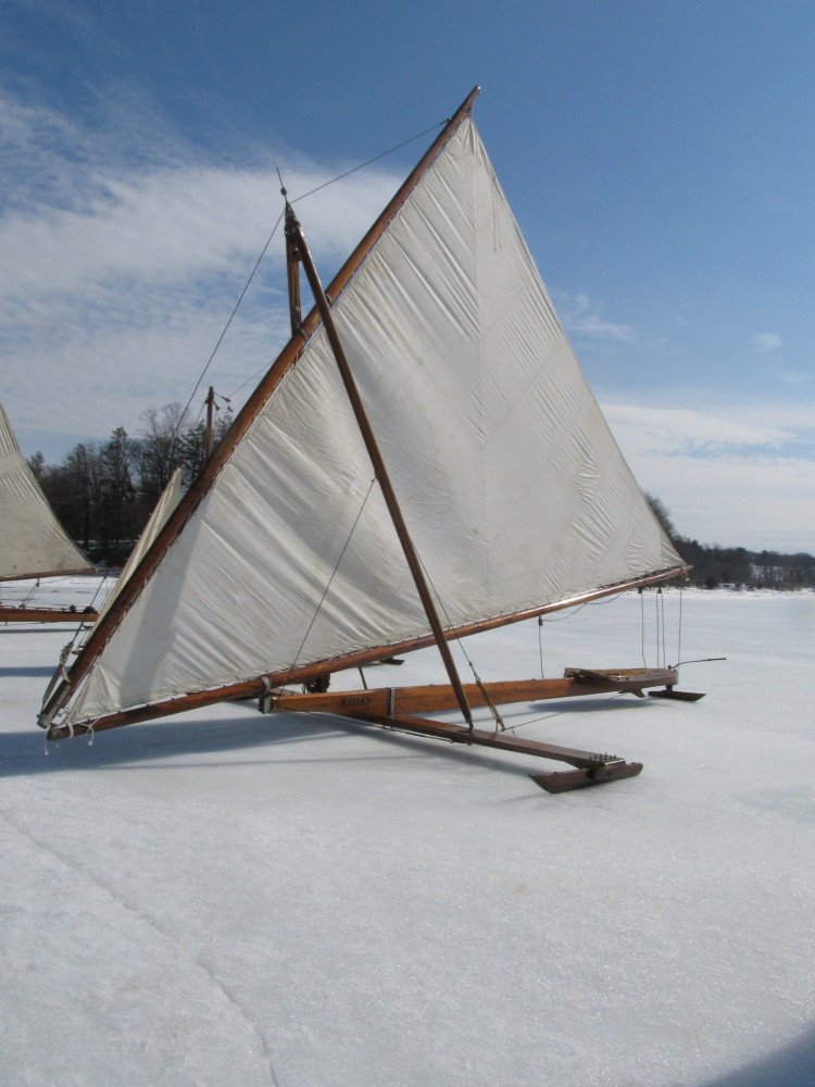
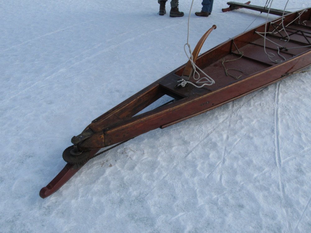
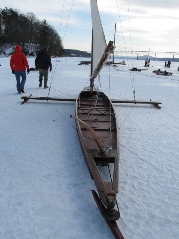
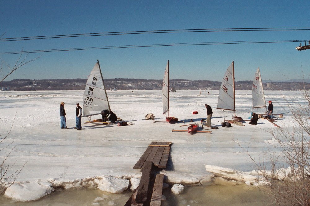
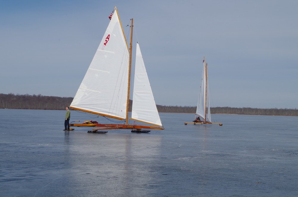
Update on ice boats photos: Herreshoff designed ice boat - only one he ever designed - note the chain and sprocket steering Lateen rigged Hudson River Stern Steerer: Vixen (1870-ish) Note for Scott - this ice yacht is rigged the same as FDR's Hawk. That's all the photos I can find for now.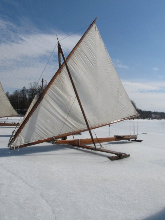
-
Requesting feedback for future MSW Group Projects
Jack12477 replied to Chuck's topic in Group Projects on Model Ship World
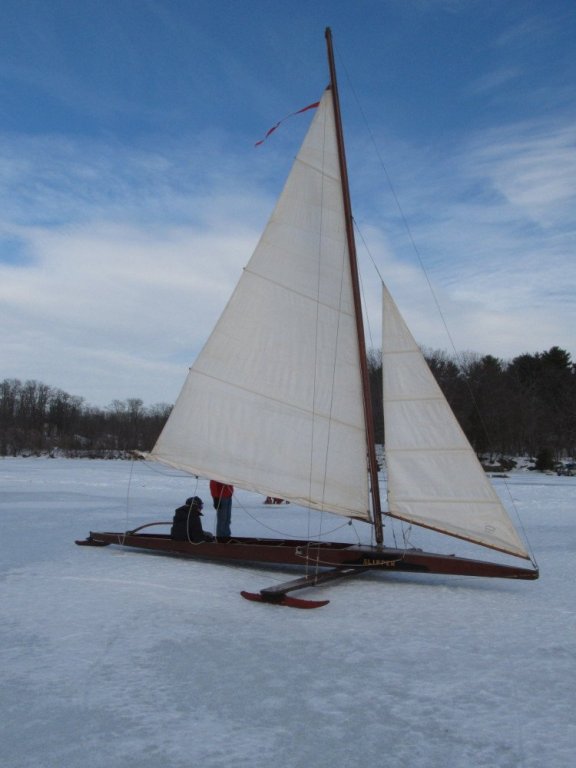
As requested DN Class Great South Bay (Long Island NY) Scooter Hudson River Gaff Rigged Stern Steerer Those are the only photos I can find in my collection at present. Photos of other classes are subject to Copyright protection so I will have to post links to those photos. Skeeters : https://www.google.com/search?q=skeeter+ice+boat&tbm=isch&source=iu&ictx=1&fir=XAEZo-i04vJO5M%3A%2ClZ4l0pEwPB4cYM%2C_&usg=__9qzC5Eb-5AB5H7C3yzTOrDZs6XE%3D&sa=X&ved=0ahUKEwih7Pqj9dbbAhVR2VMKHdPlAy4Q9QEIPTAE#imgrc=XAEZo-i04vJO5M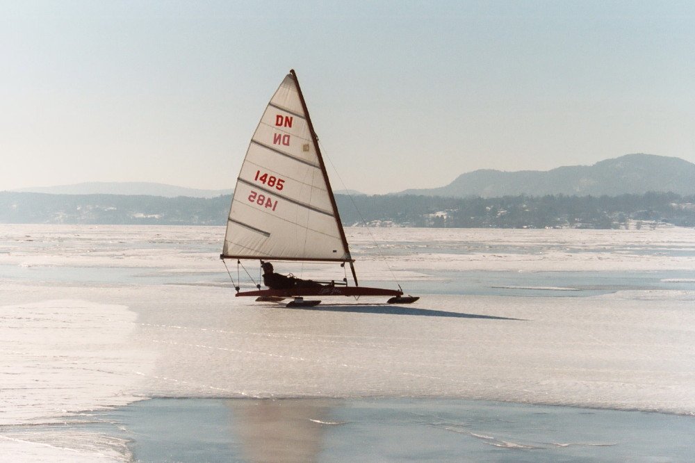

-
Requesting feedback for future MSW Group Projects
Jack12477 replied to Chuck's topic in Group Projects on Model Ship World
Chuck mentioned "ice boat design concept" in his original post. Does anyone have any interest in ice boat model(s) in general ? MikeR and I each have a build log of two of the many styles of ice boats; there are a number of other designs, from Arrow, Nite, Scooter (Great South Bay Long Island), Skeeters, to name a few. If anyone has an interest post a comment below.