JSGerson
-
Posts
2,647 -
Joined
-
Last visited
Content Type
Profiles
Forums
Gallery
Events
Everything posted by JSGerson
-
 FYI - Because white styrene has a tendency to yellow over time, painting it, is a must. Jon
 -
My biggest problem is drilling into the brass. My typical manual twist drills used with a Dremel rotary just don't want to bite into the metal. So making holes into something like those block pieces is a mystery to me. Jon
-
I did not mean to put a cramp in your in your quarter gallery efforts. I just accepted what I did on my model as the best I could do at the time. Your quarter galleries are better than most that I have seen. Jon
-
I never was satisfied with my results after a least 4 attempts too. The result you posted looks great except (and I'm being very picky and wished mine looked as good). your lower panes are larger than the two rows of panes above. They should all be of the same spacing. You got the window frame itself right, something I failed to do. In your post to Mustafa, you mentioned that the glue clouded up the plexiglass. You might try canopy glue, the stuff used to create pseudo glass in small openings. I used mica for my glass. It is strong, clear, and can be made very thin by removing layers by splitting it, is flexible when it that thin, and you can cut it with a scissors. Jon
-
You did a beautiful job on those companion ways. How did you do it? How did you make the cube joints and the finial? I checked xKen's method but I don't have a metal lathe or the skills and experience to use it even if i had one. Jon
-
CCoyle. glad your safe as well. I am surrounded by trees, lots of tall trees, but none fell near me. The ground was littered deep with small branches, leaves, and pine needles; however, a dozen or so trees on my street did come down. Nobody, as far as I know, no one was hurt in my area. There are still isolated pockets of power outages, and the stores are still restocking. But, the worst is over. Take care, Jon
-
USS Constitution by mtbediz - 1:76
JSGerson replied to mtbediz's topic in - Build logs for subjects built 1751 - 1800
You also have something else that is particularly important, skills, patience, and tenacity. It is a pleasure watching you. Jon -
Just a quick update, as many of you know (or not), a major Cat 4 hurricane, Helene passed through Florida, Georgia, and Tennessee, just touching on western South Carolina this passed Thursday and Friday. I live in western South Carolina, a half hour drive to Augusta GA (home of the Masters Golf Tournament), So we got a good taste of the fury that storm packed. I was lucky, and lost power only for two days and had a little erosion damage. Some of my neighbors had more extensive damage to their property. So, I'm OK and am back in the shipyard. Jon
-
USS Constitution by mtbediz - 1:76
JSGerson replied to mtbediz's topic in - Build logs for subjects built 1751 - 1800
A very neat look compared to mine. Well done! Jon -
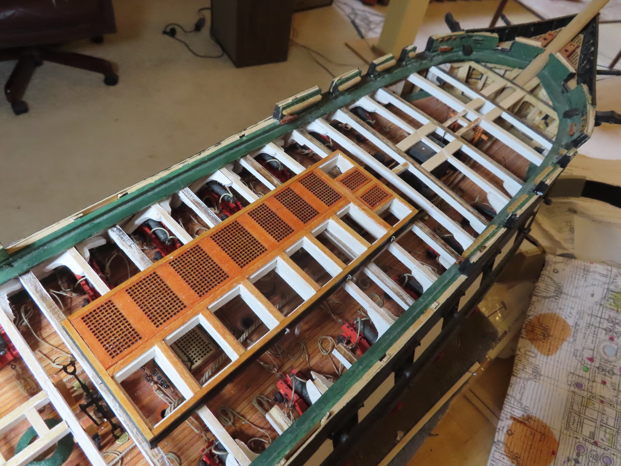
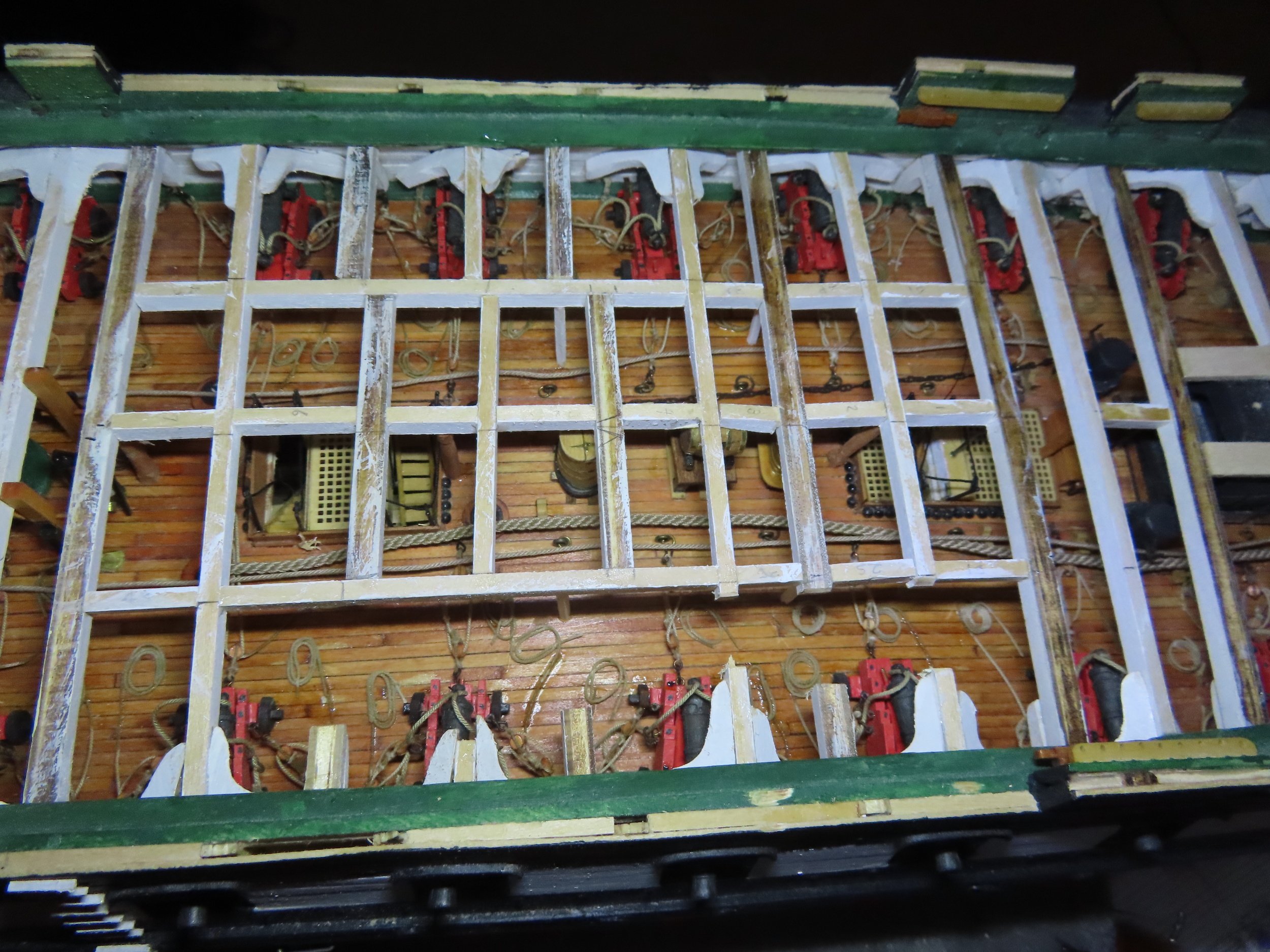
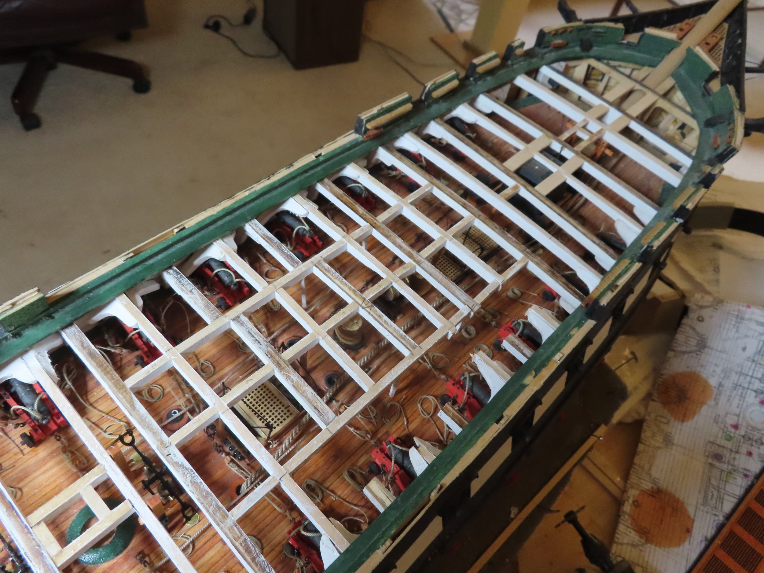
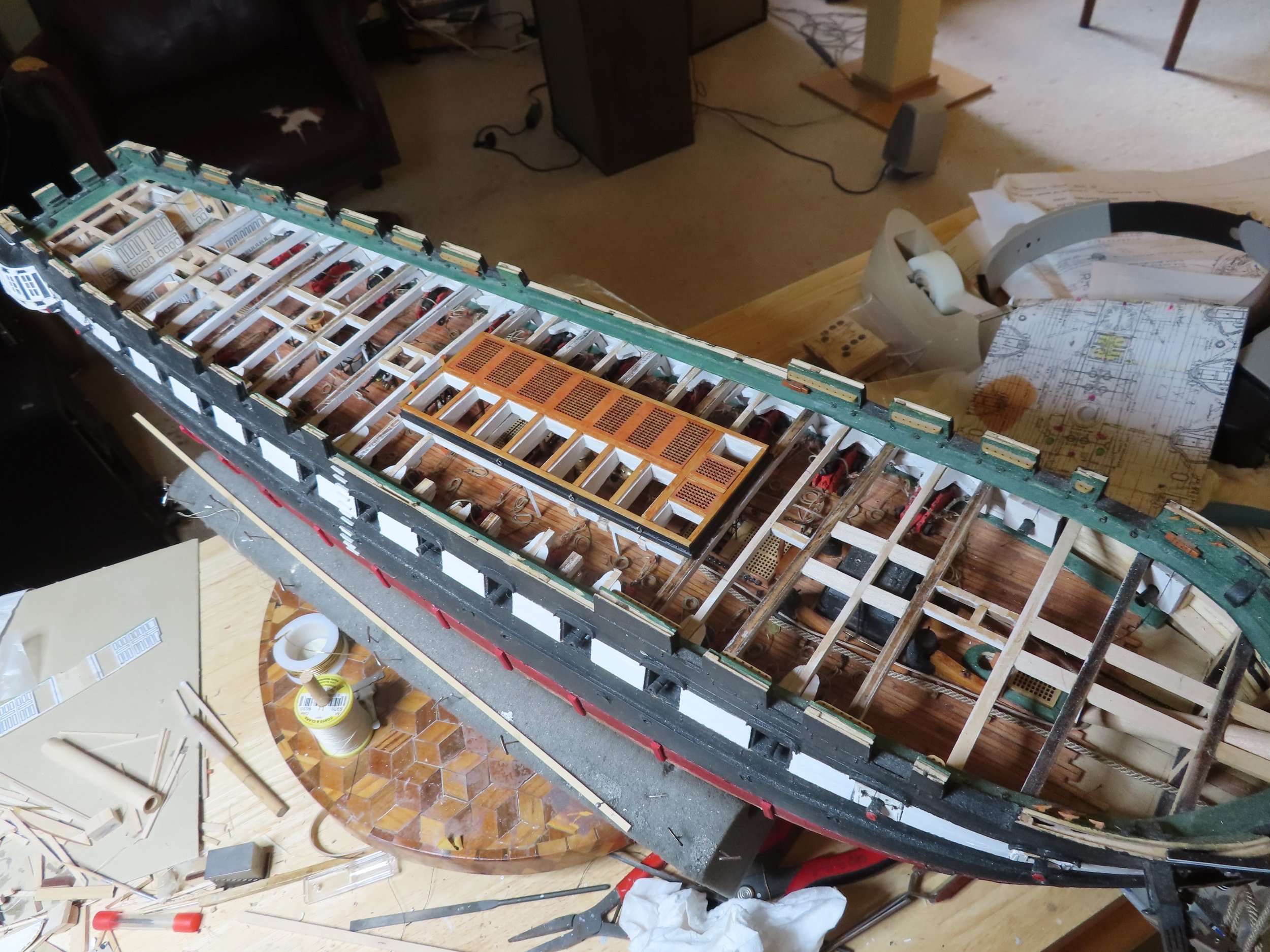
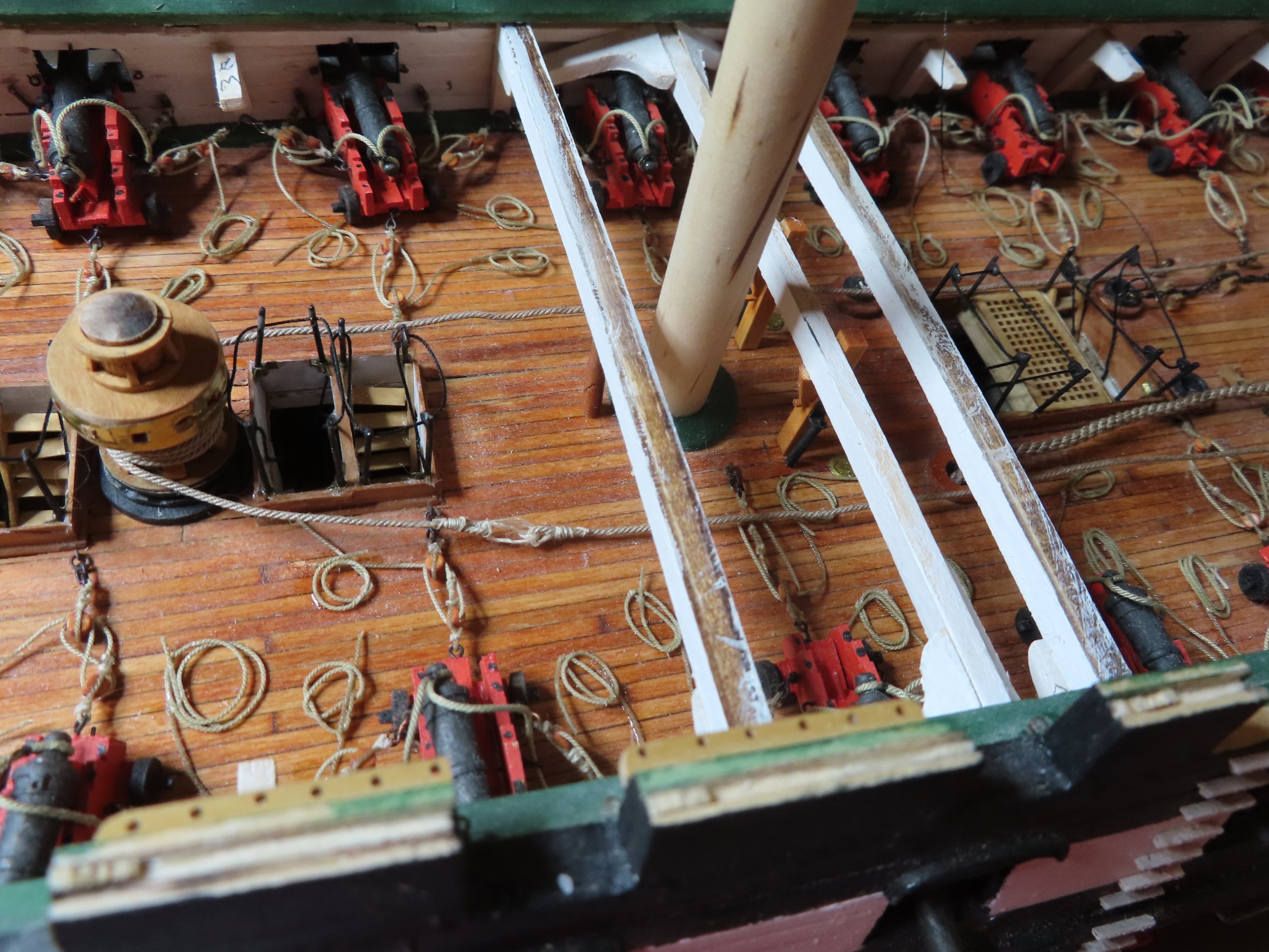
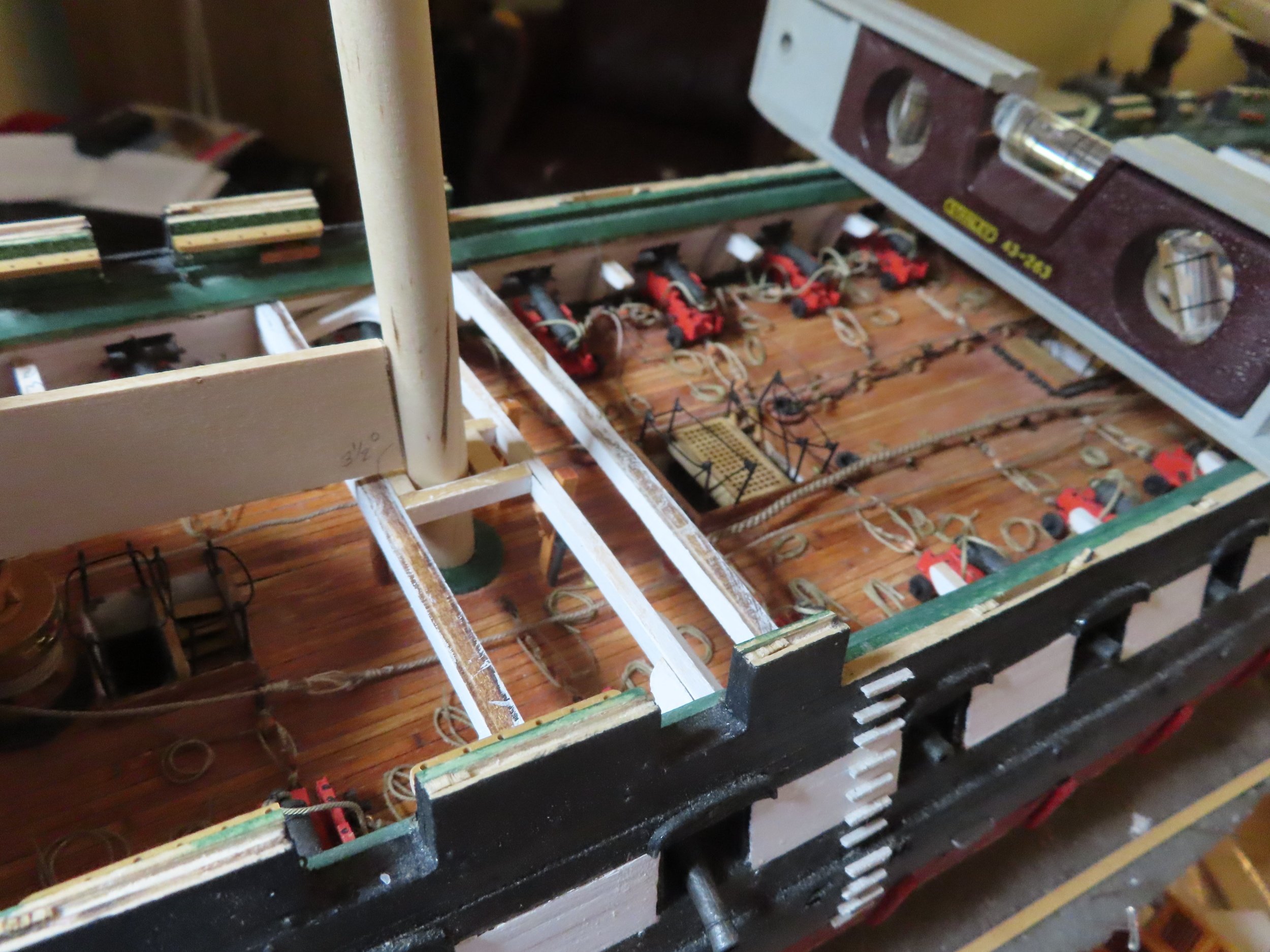
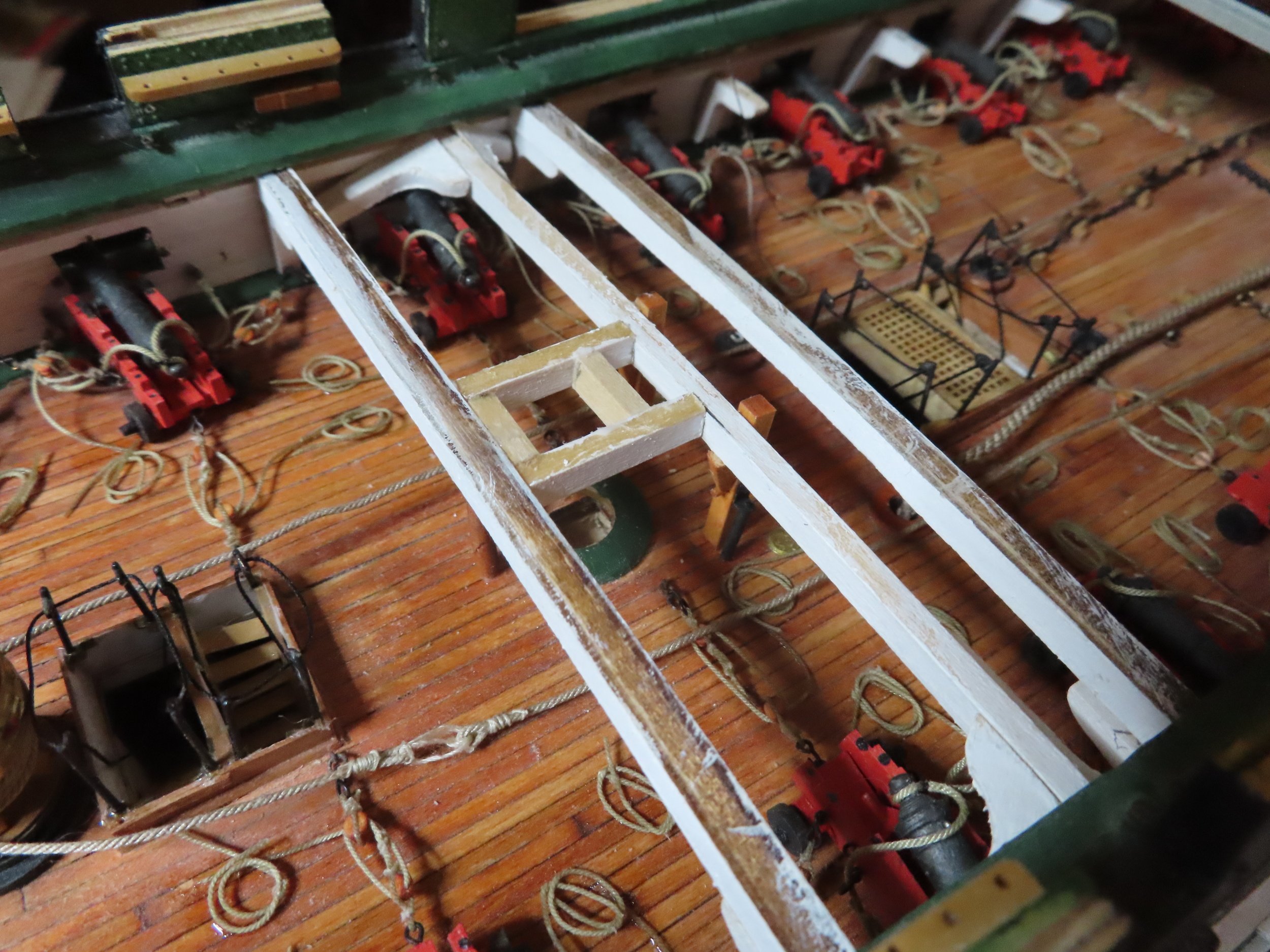
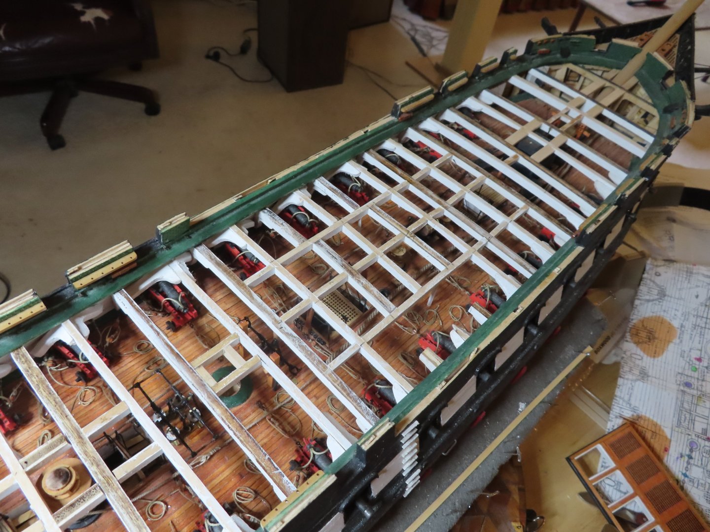
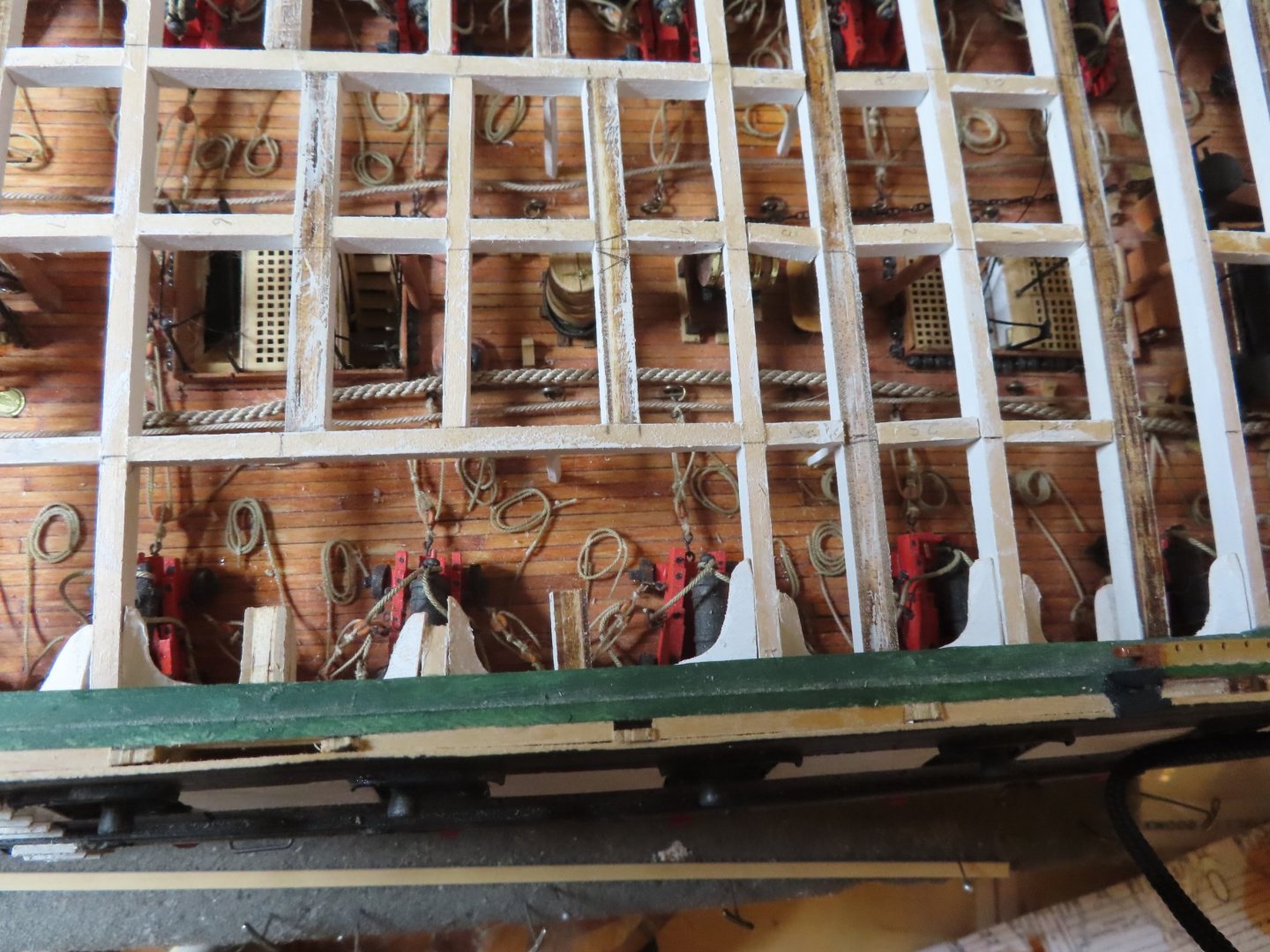
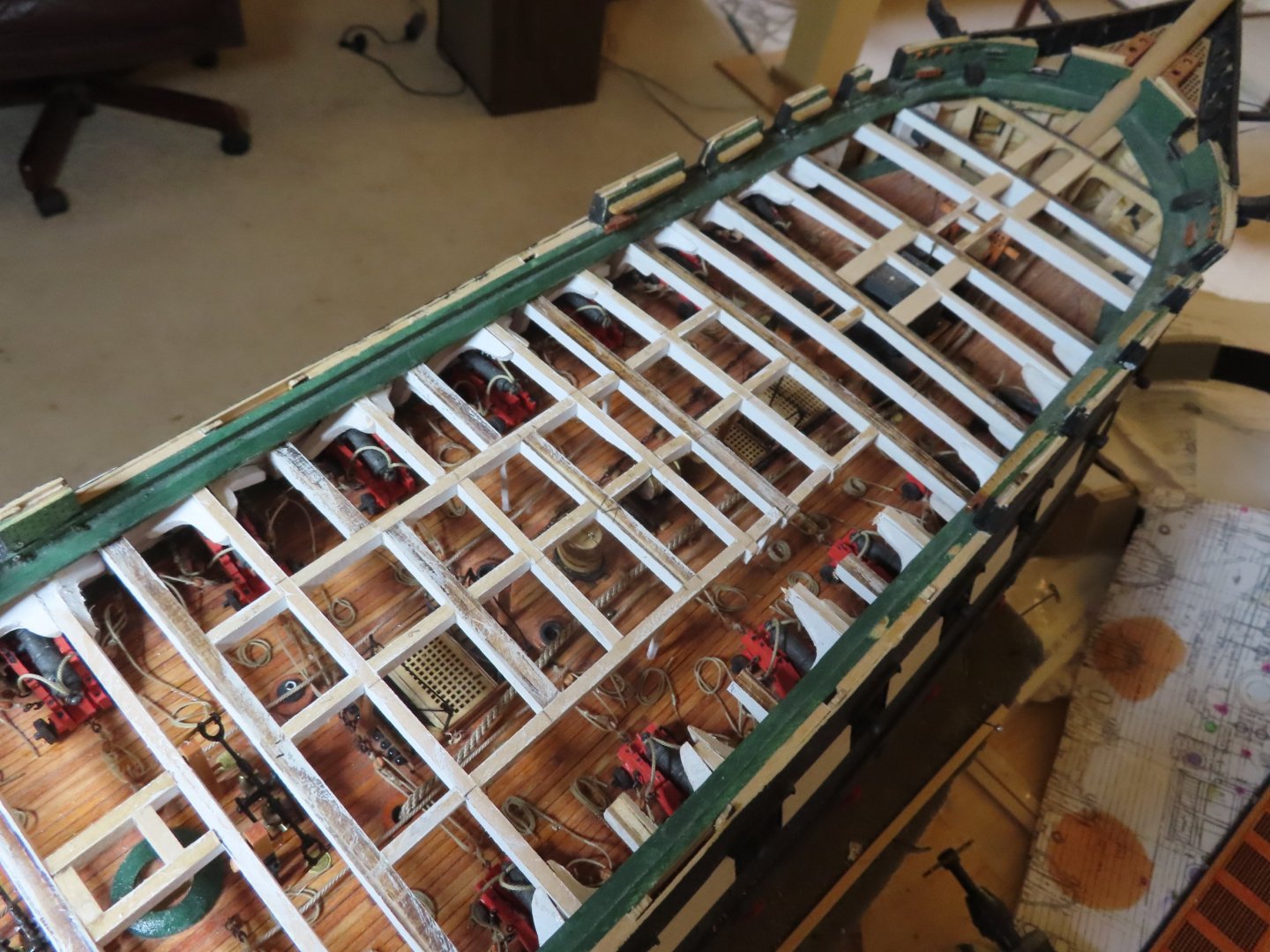
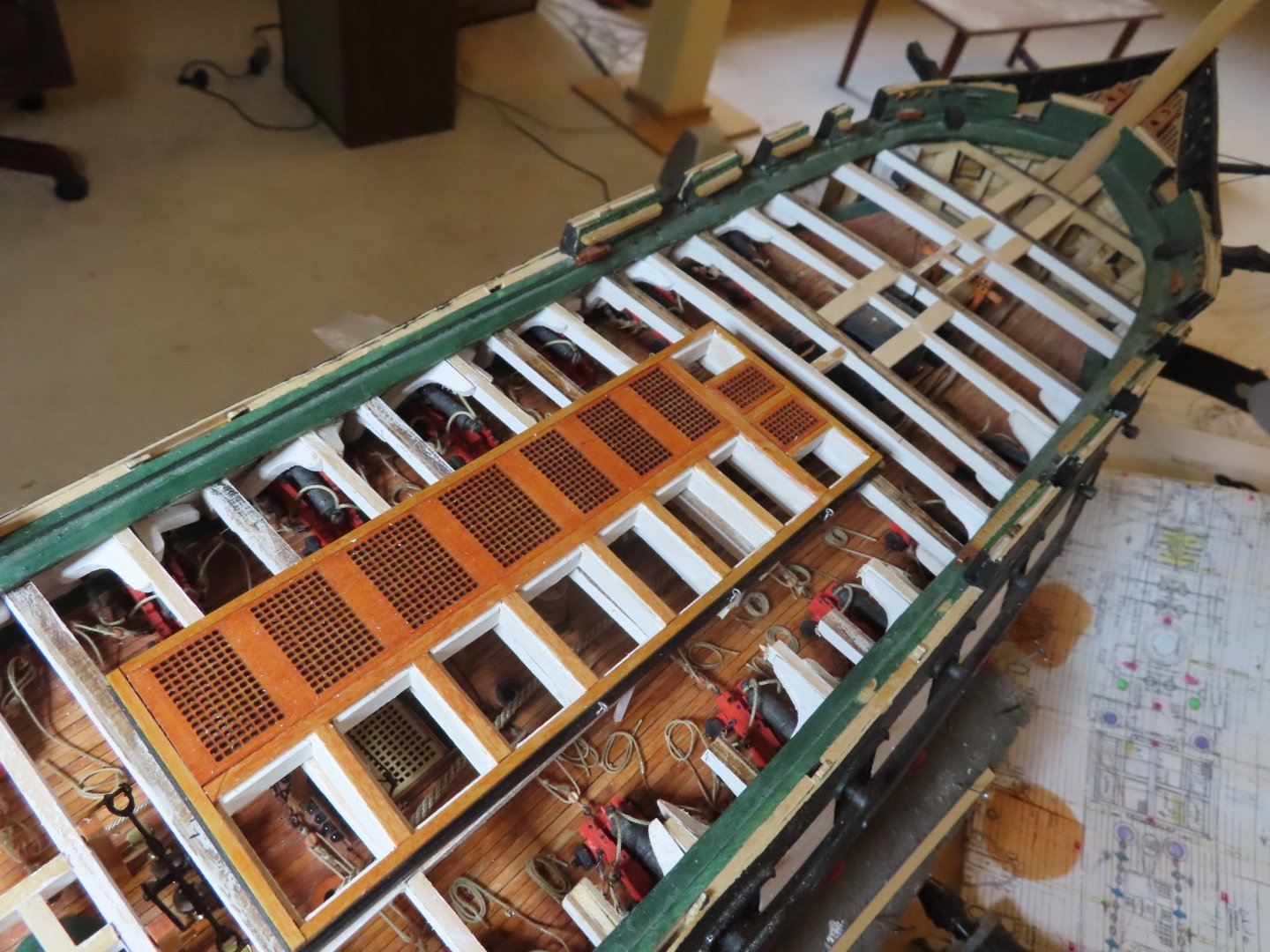
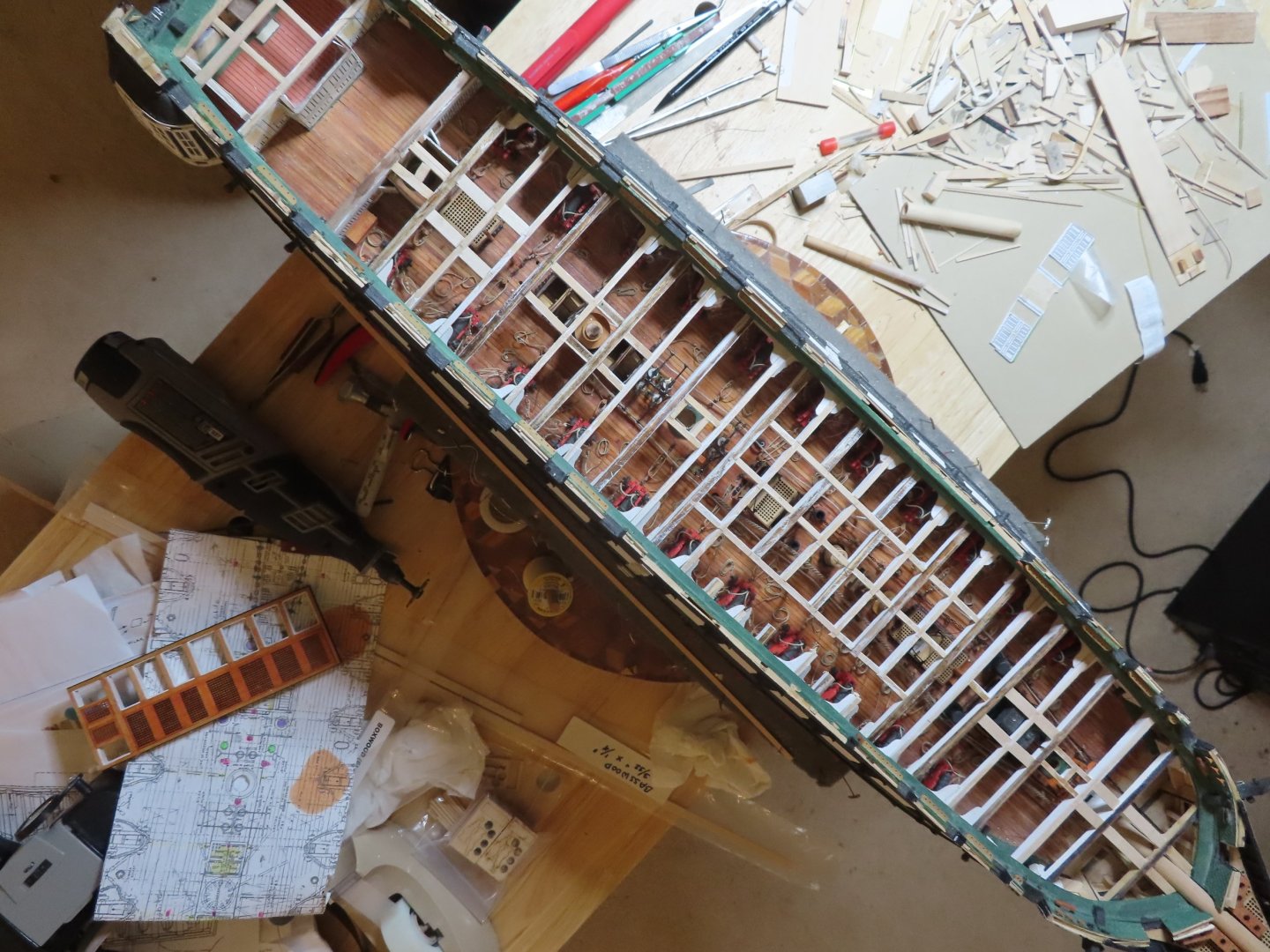
This post shows more of the same. I added more spar deck beams, gun deck columns, both the white square cross section ones and the natural wood round ones, knee braces, and the main hatch framing support beams. You will notice that the starboard side is missing some beam sections. I realized that even though I did not add all the spar deck structure, viewing the gun deck was getting a bit obscure. To alleviate this a little, I made it look like the beams were cut out. However, I made this discission after I had installed three whole beams supporting the main hatch. The beams were cut, the leftover stubs were left in place. Where I intentionally installed partial beams, I added little stubs to make it appear they were cut after most of the picture were taken. Additionally, you may have noticed that the beams under the main hatch do not run straight across. This is my solution to the problem I discussed in an earlier post about the structure of the main hatch. The laser cut grids making up the main hatch do not conform to any plan I’ve seen including the kit plans. In keeping with the idea of the cut-away look, the top surfaces of the structural beams and supports were not painted so it would look like the spar deck planking was removed revealing raw timber below. A side effect of this is where there will be planking and other things items attached to them, the glue works better on bare wood. Some of the pictures below show the main hatch dry fitted in position


-
USS Constitution by mtbediz - 1:76
JSGerson replied to mtbediz's topic in - Build logs for subjects built 1751 - 1800
Very creative with the furniture! Well done! Jon -
Hey, I'm a life long 77 year old bachelor with no one to answer to except myself and the cat, so I've got time to gather stuff and organize it for easy retrieval. I try to share the wealth. Jon
-
Now I know what my model should look like! Nice job!! Jon
-
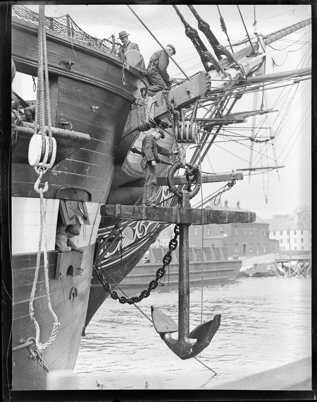
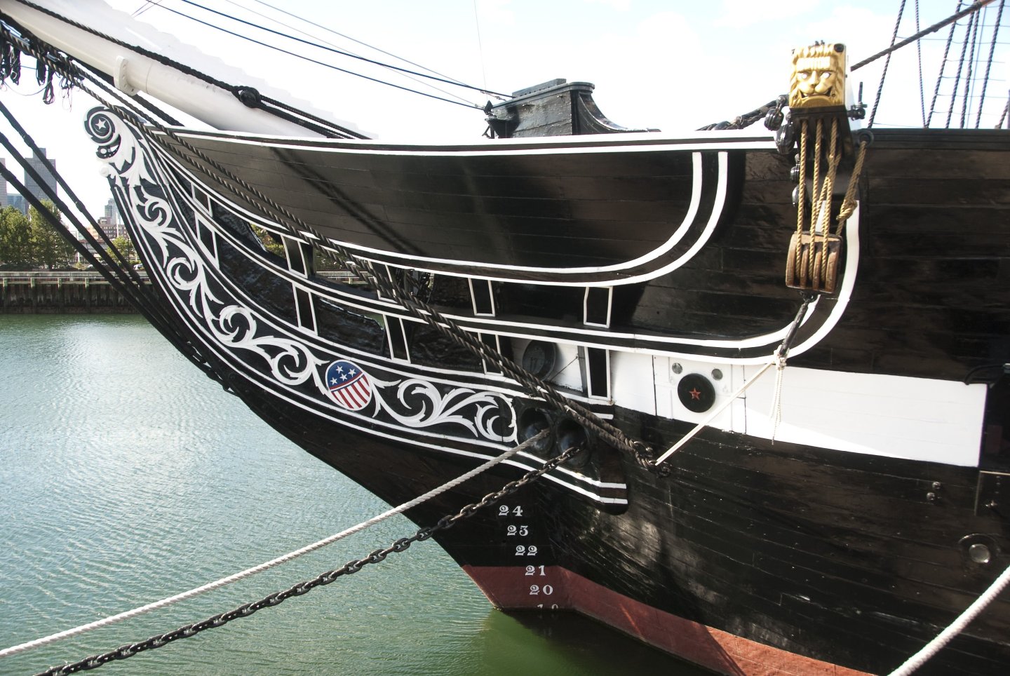
I have approximately 25,500 images of the ship from the very earliest in 1857 to the present showing all kinds of detail from multiple angles and multiple sources (public & private) that I have collected since about 2014. Should you or anyone else need a image showing particular detail, there is a good chance I may have it. Just ask. Jon
-
For those who did not take` the time to read this vintage text, I copied the section in modern font for your convenance: Composition for Blacking Guns lbs. lbs. Black lead 20 Red lead 10 Lampblack 14 Linseed oil 18 gals. DIRECTIONS: First the above mentioned articles must be ground very fine with boiled oil. PROCESS Boil the oil sufficiently until every appearance of froth subsides – the best way is to have two iron pots, dividing the oil in each pot, put the black lead in the boiled oil, and boil it half an hour. The 10lbs. of red lead must be put in the other pot, after the oil is put on the fire and boiled half an hour; after which, put the lampblack to the red lead and boil them together half an hour. – The two pots must be put by until nearly cold, when by the means of an iron ladle the ingredients must be shifted from one pot to the other, until they are naturally well mixed. CAUTION. Great care must be taken during the time the liquor is preparing to prevent its boiling over, and in particular to keep stirring the ingredients during the time of boiling. Marshall’s Practical Marine Gunnery CONTAINING A VIEW OF THE Magnitude, Weight, Description & Use, OF EVERY ARTICLE USED IN THE SEJ GUNNER'S DEPARTMENT, IN THE NAVY OF THE UNITED STATES., 1822, p94-95
-
Gregg, well I don't have ALL the resources, but I do have a bunch😛 As for printing them out full size, I haven't done that as it is costly and inconvenient. I did have the kit's plans copied full size so I could mark them up, fold them in torturous ways, and if they get damaged, no worries. I print out what I need on a regular inkjet printer on standard paper using PowerPoint. When I need to print to model scale, it's by trial and error because PowerPoint can't print to a given scale on command. Additionally, I may need to tape together multiple sheets to get the desired printed image, which I admit is a crude method. Most of the time I just zoom in and out on the computer screen. The US Navy plans have the actual full scale dimensions so it's just a matter of scaling down the numbers for a lot of things. Jon
-
Dputxler, you can get the US Navy plans here: https://ussconstitutionmuseum.org/discover-learn/modeler-resources/ Jon
-
Very sharp eyes! Yes, I spotted that too. luckily the pumps were only dry fitted when the photo was taken. That misplacement was corrected almost as soon as I made my posting. I didn't think any one would notice. I appreciate your attention to the details. Thanks! Jon
-
mtbediz - I appreciate the kudos, especially from you! Jon
-
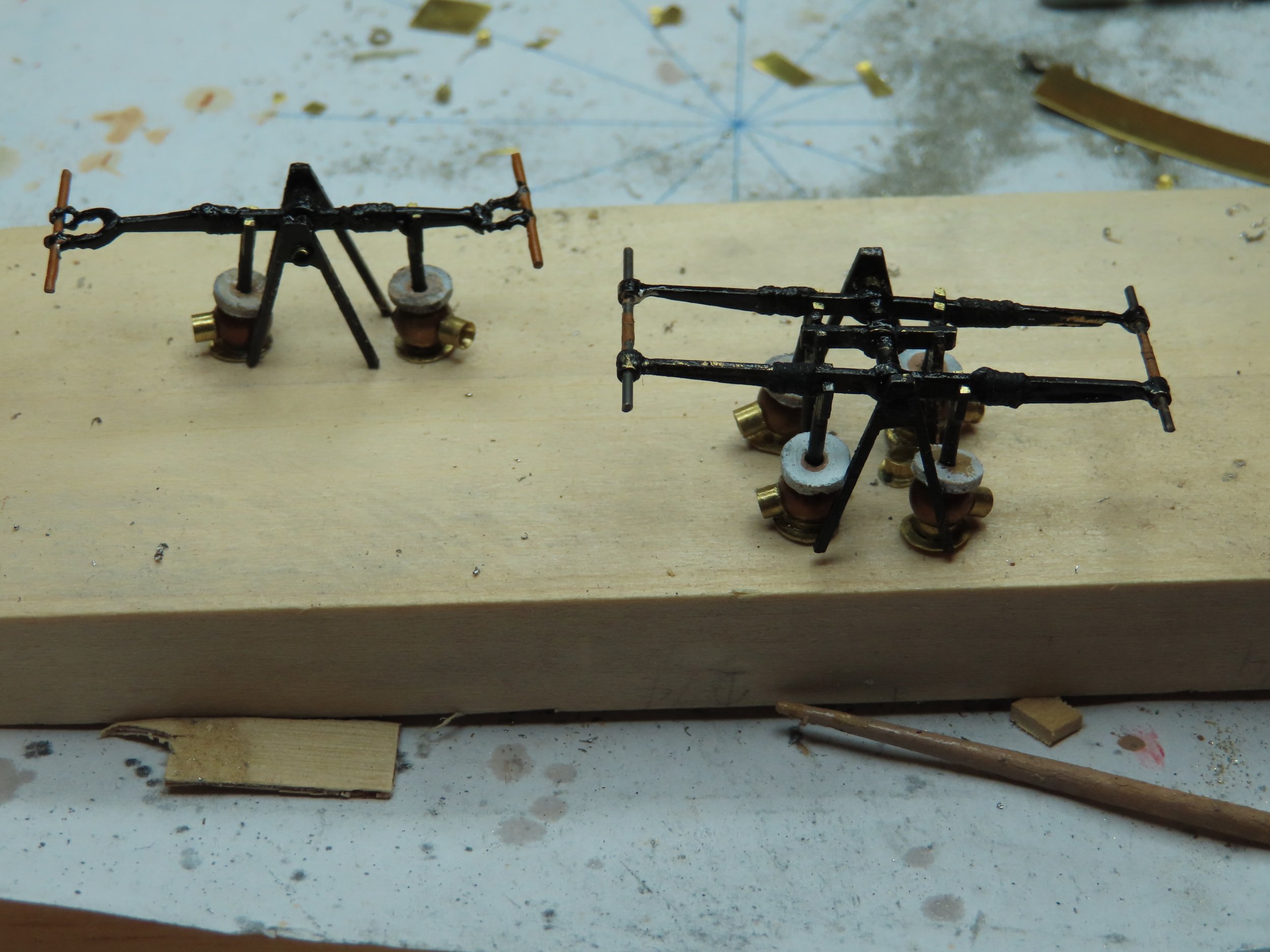
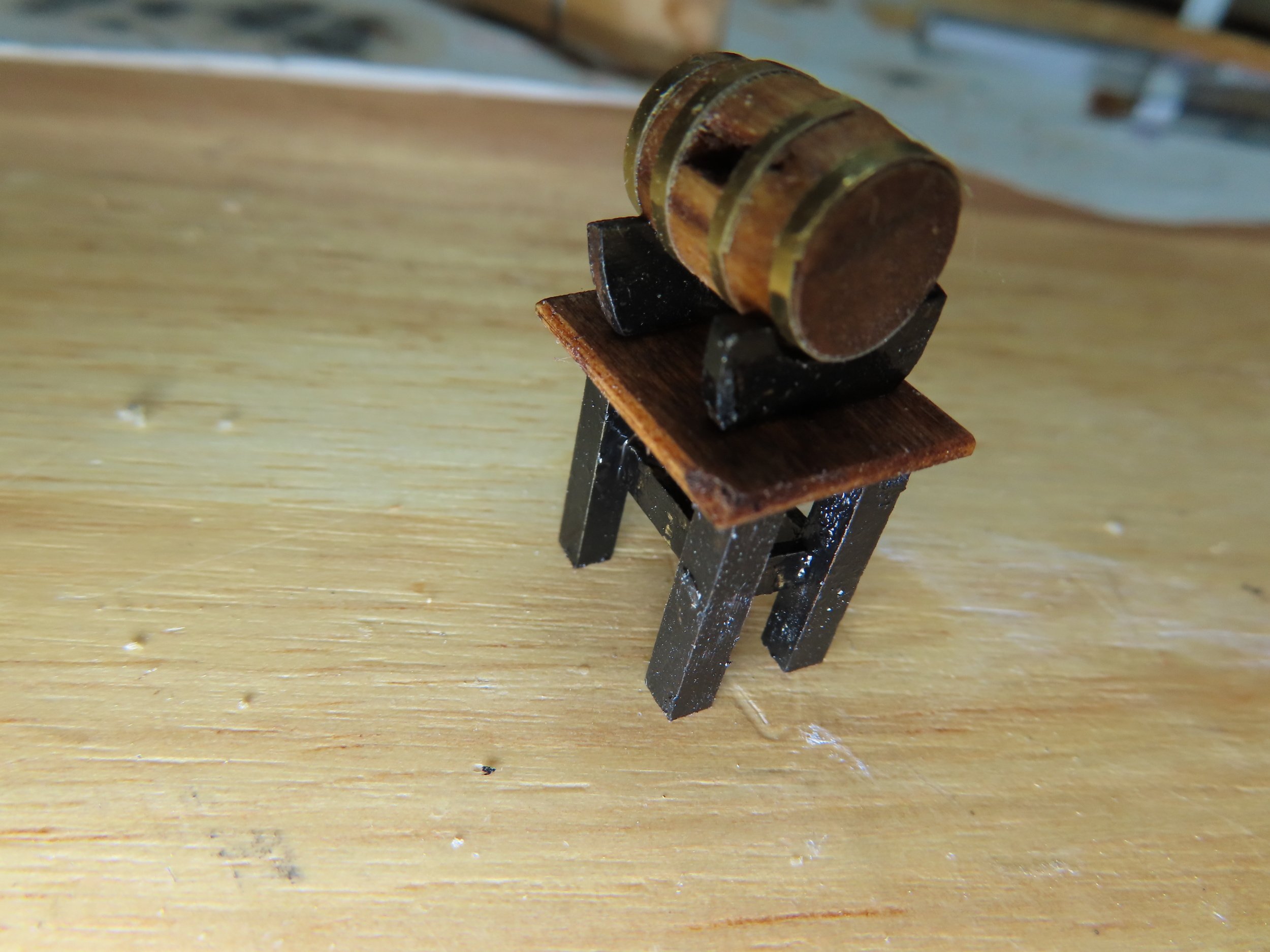
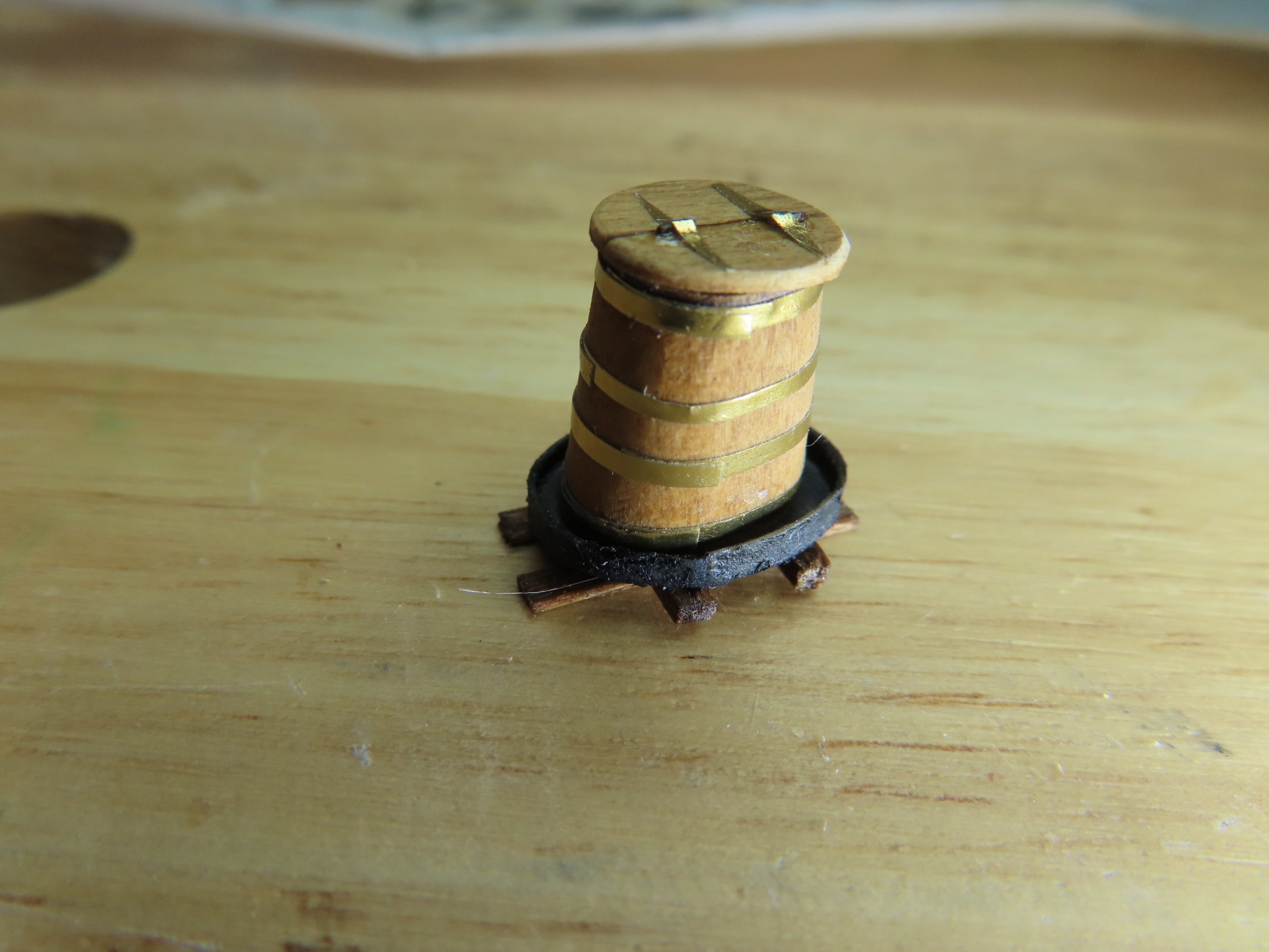
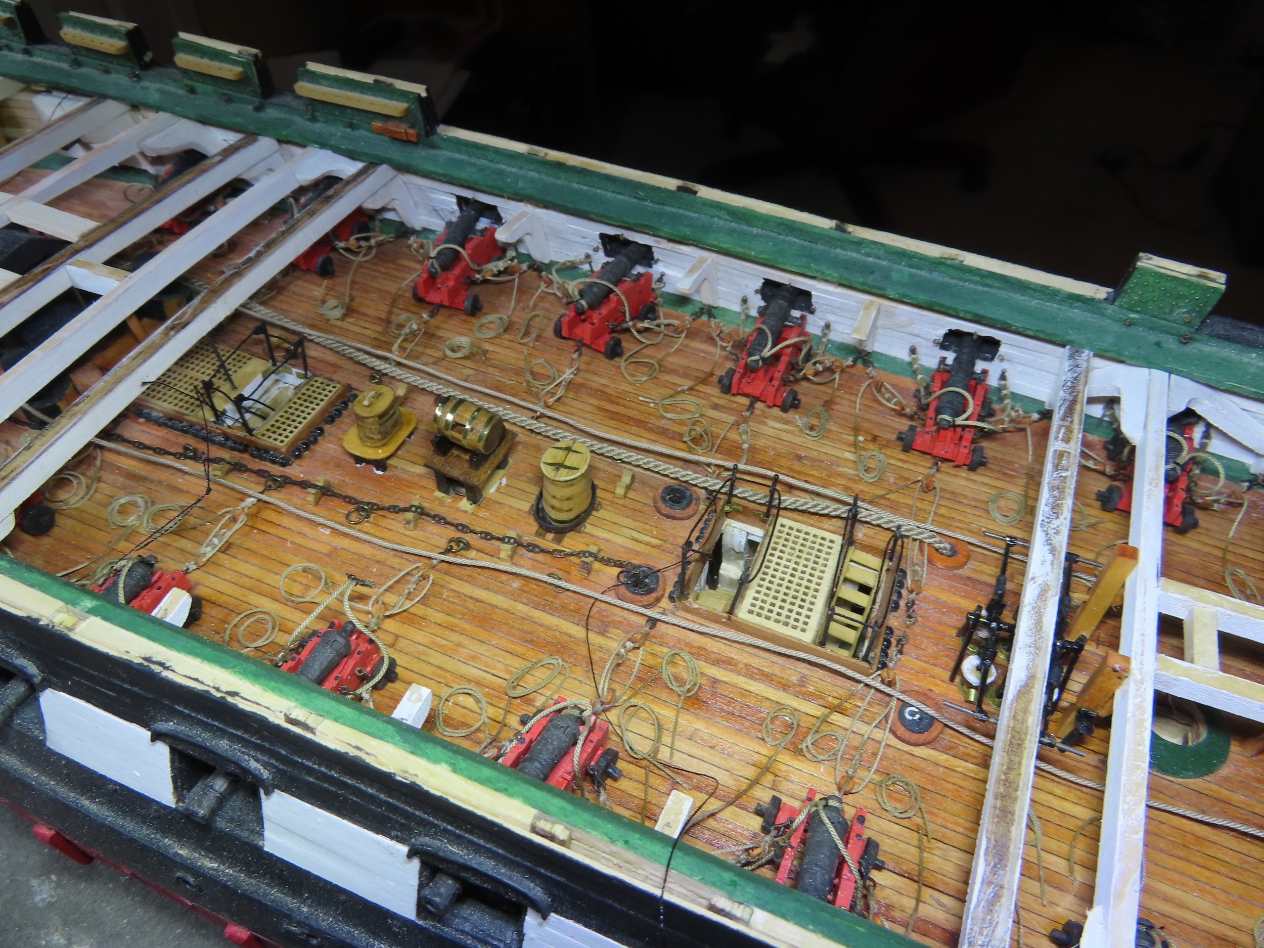
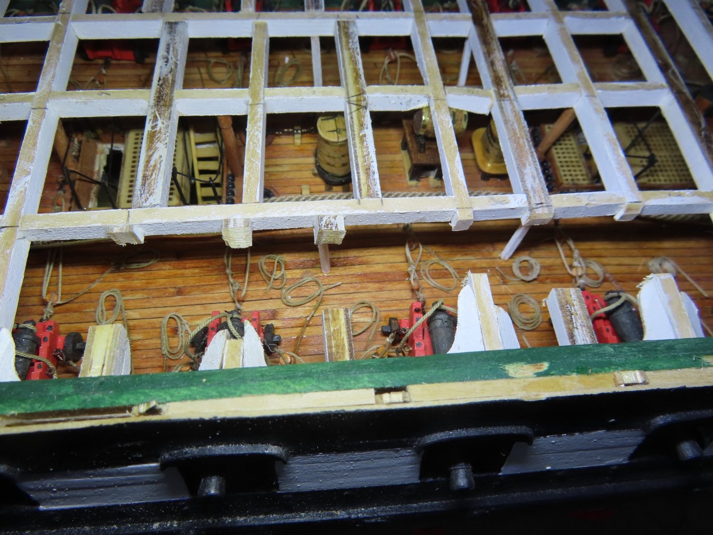
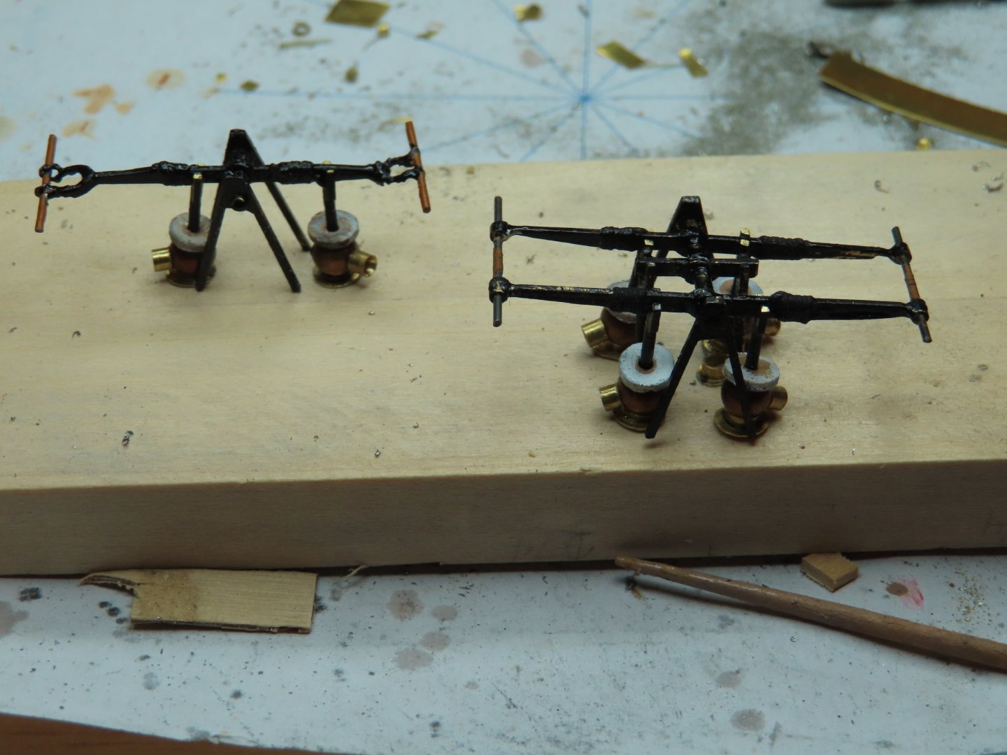
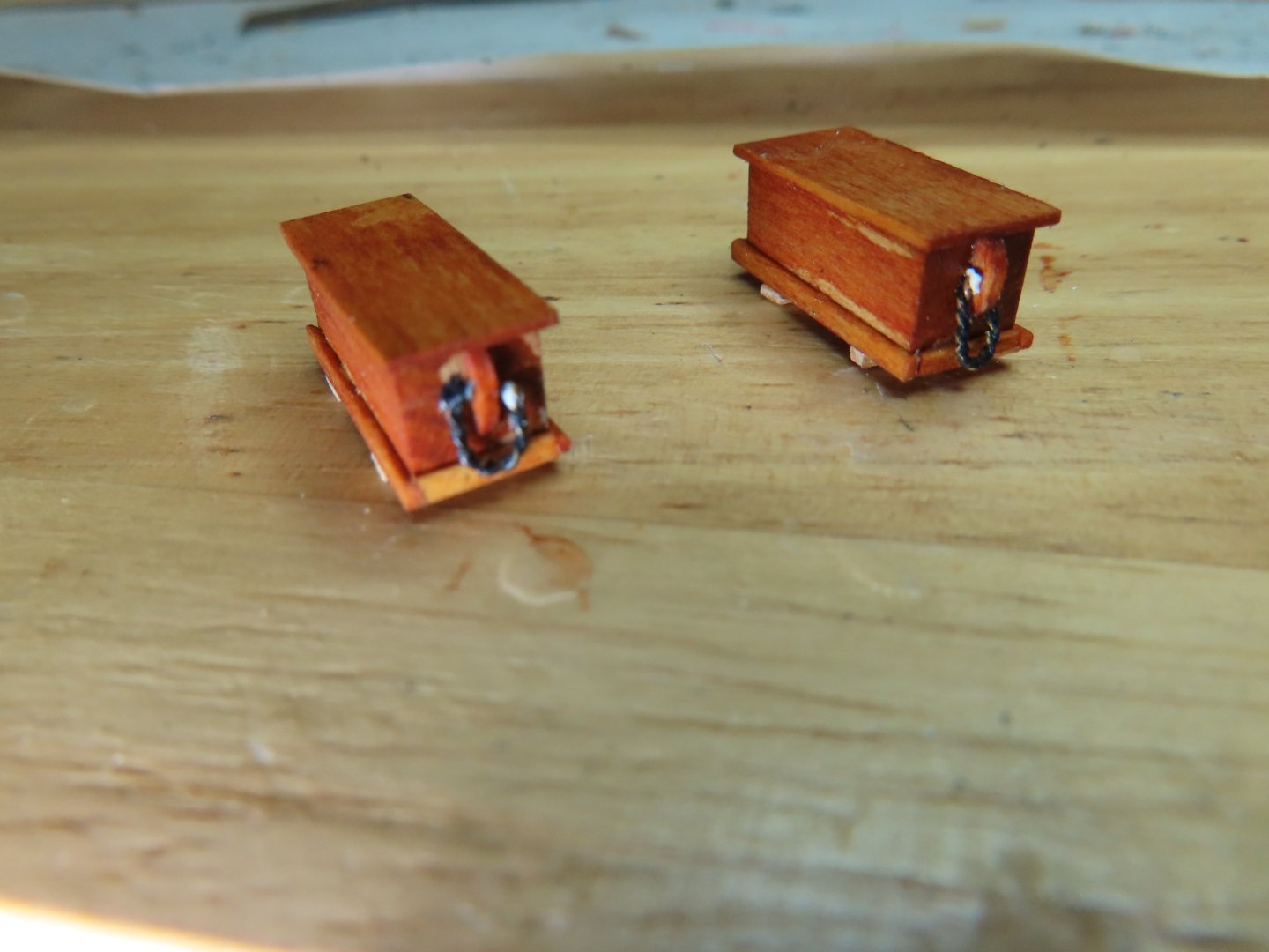
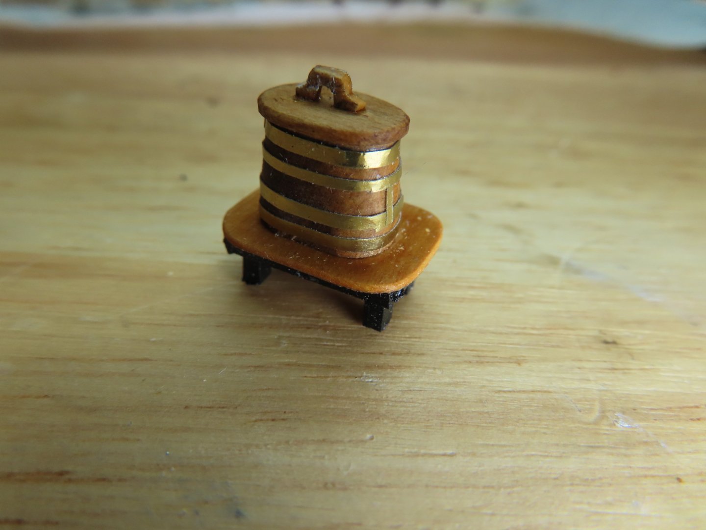
At this point I installed the last of the gun deck furniture previously made four years ago: double pump quad pump sea chest scuttlebutt & table grog cask & table harness cask Still to come, the remaining spar beams and associate accoutrements to support the main hatch.


-
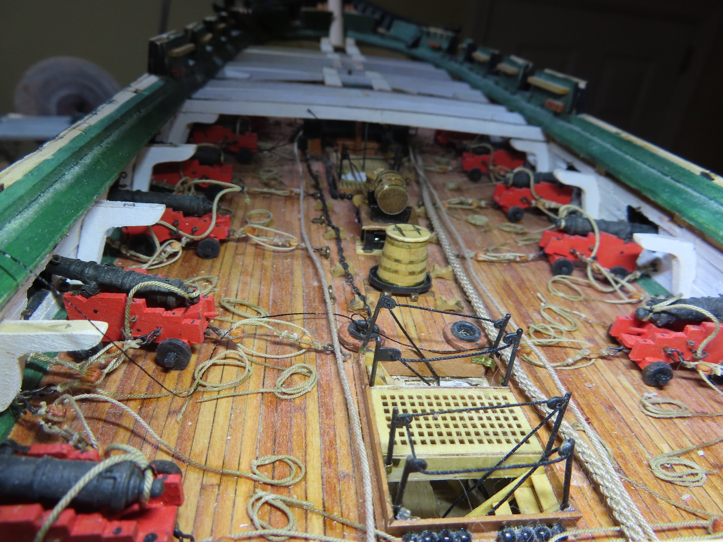
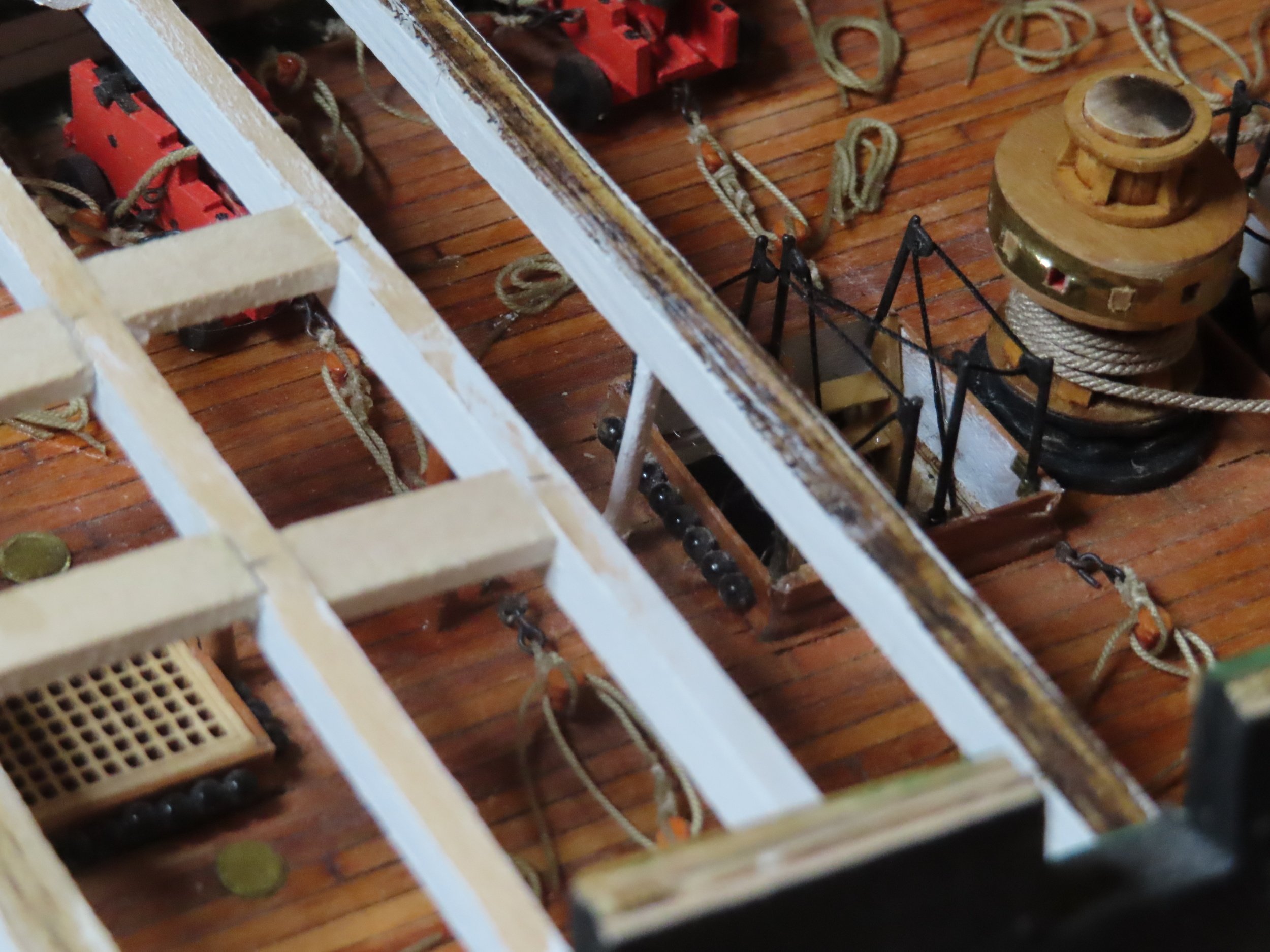
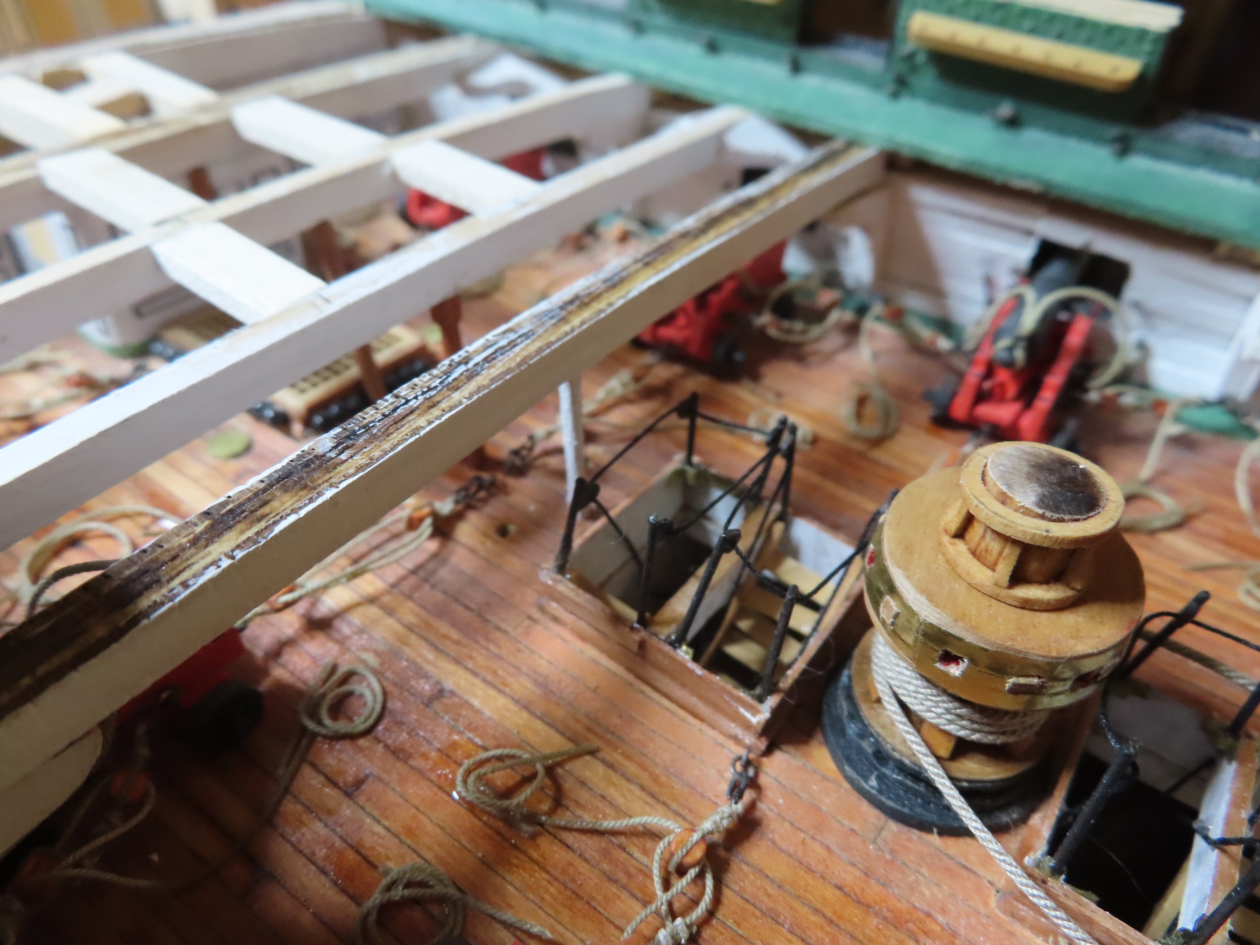
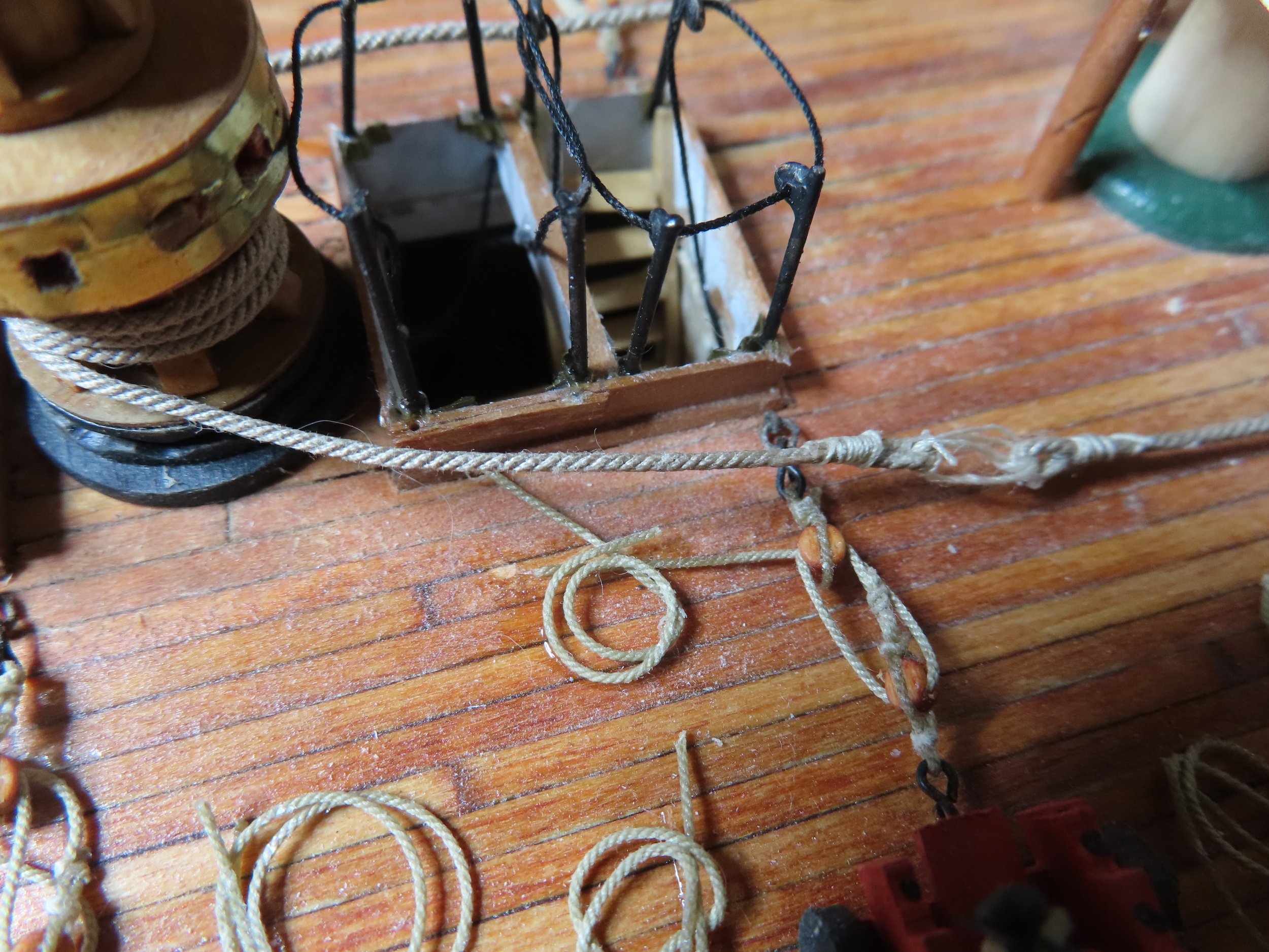
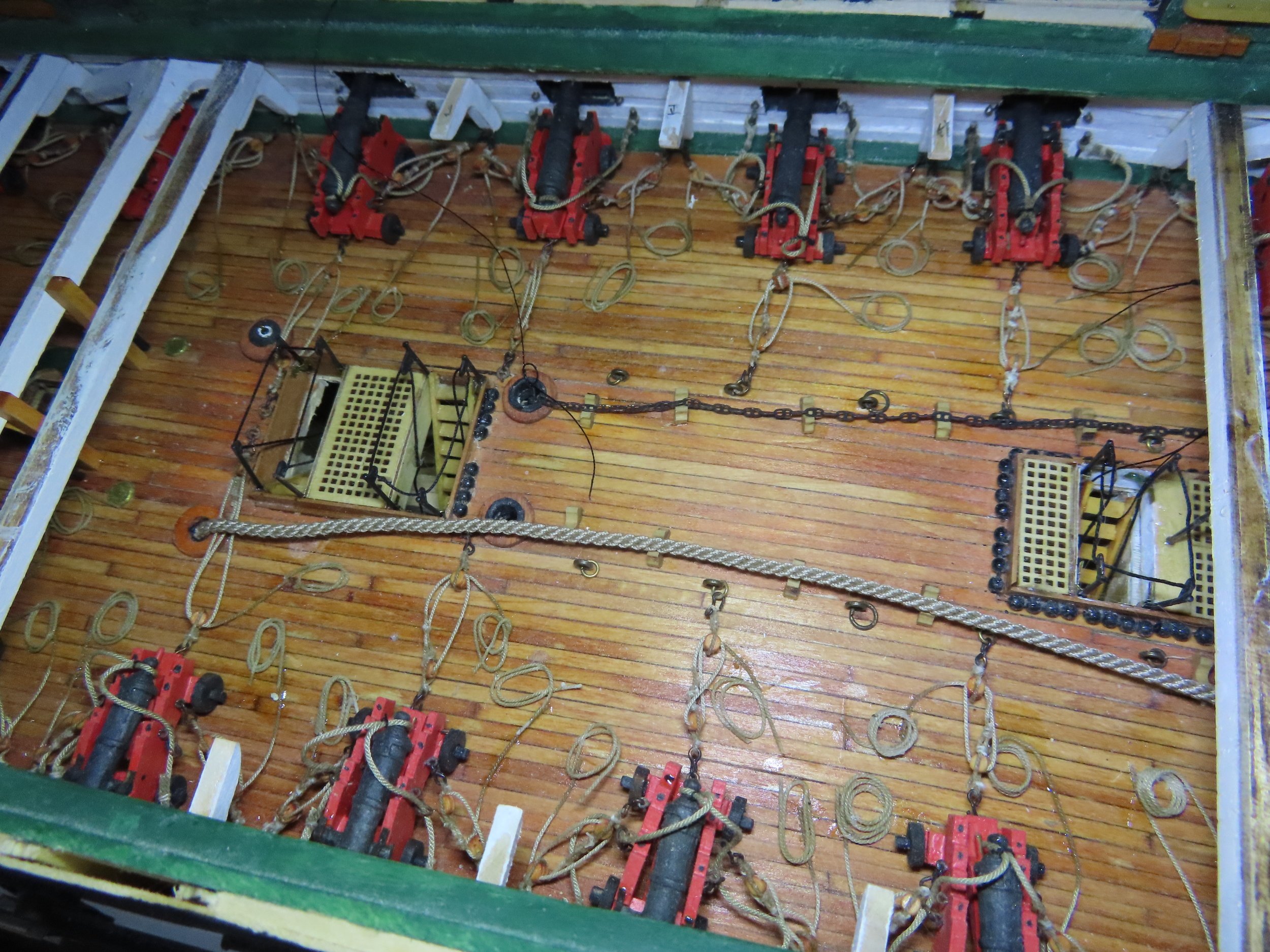
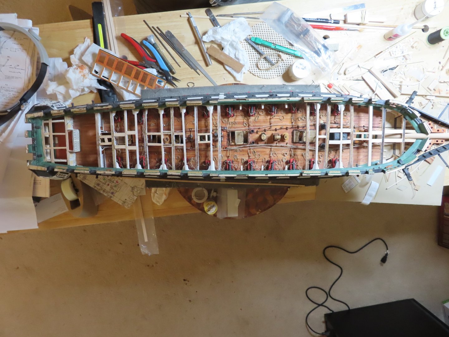
Getting back to the ladder hand ropes, I left the messenger rope loose on the deck as if it had just been released from the cable or chain and the ladders were put back in place. Technically, either the messenger is in place, or the hatch covers and ladders are in use, not both at the same time. In either case, it’s all going to be difficult to see and the layman certainly won’t know anything looks out of place. Next, more spar deck supports and their associated diagonal knees at their bulwarks were installed aft of the capstan. Additionally, some “temporary” (as marked on the US Navy plans) supports (painted white) were added as well. It’s getting really crowded on the gun deck.


-
The messenger rope was installed first since it was wrapped around the capstan. A spliced loop end was created for each end of the messenger rope first. Then the rope was wrapped around the capstan three complete times. The rope went along the gun deck to the bow around a support and back again towards the capstan. There would have been a roller mechanism for this at the apex of the turn in the actual ship, but that will not be seen in this model. The two end loops of the messenger rope were then lashed together. The lashing had to be done using needle and thread in the confined space of the model and was a bit delicate to do. The anchor cable and anchor chain were inserted through their respective hawser holes in the bow, down the length of the deck using anchor chain guides previously installed, and into the pipe in the gun deck. Neither ends of the cable nor chain were permanently installed pending attachment of their anchors at a later date. Oh, I also installed the framework for the main mast so it has a rake of 3.5 degrees.


-
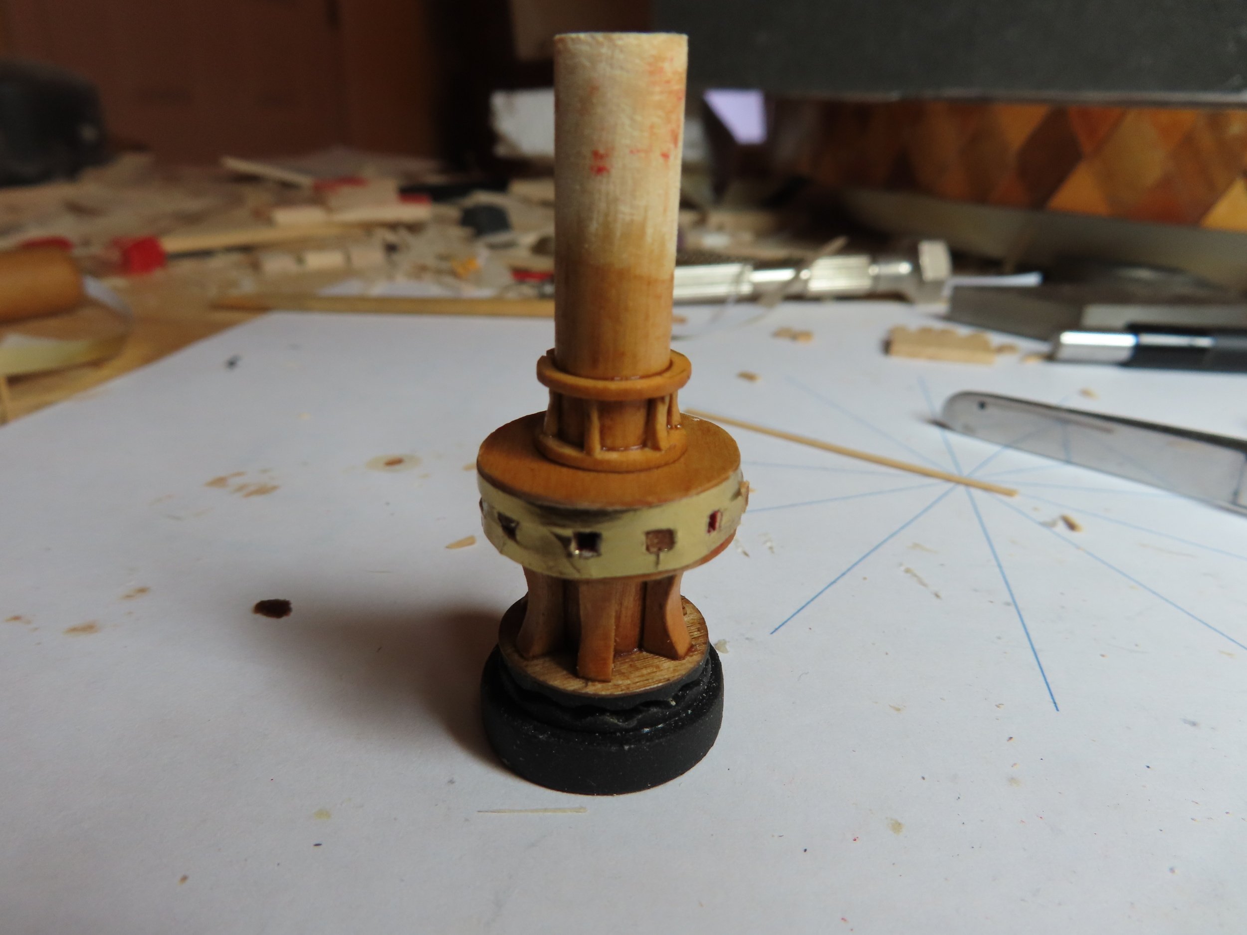
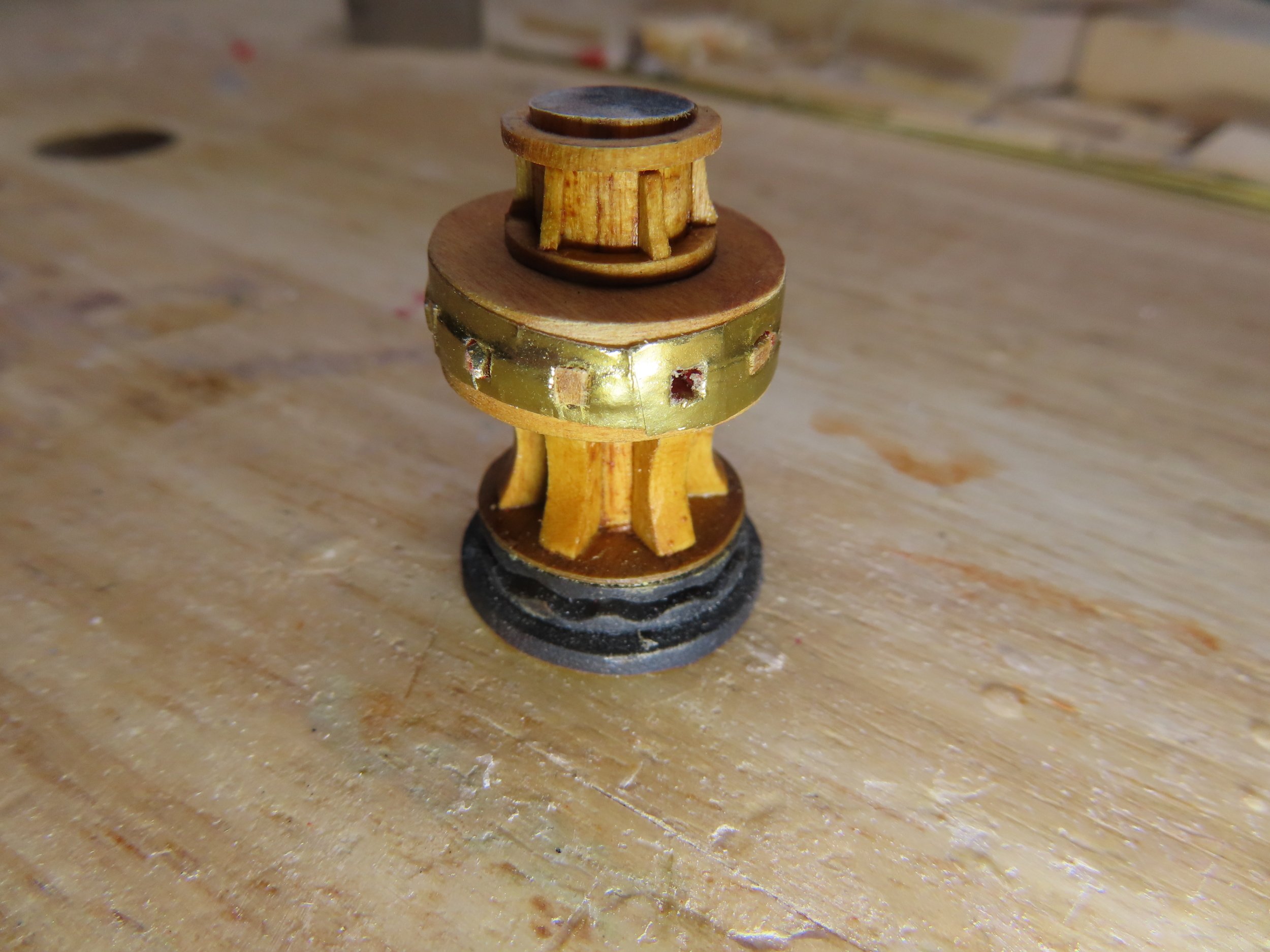
When I last worked on the gun deck capstan, I left it in such a manner that I could fine tune its height to the proper length when I knew how long it had to be. With the spar beam dry fitted above it, the capstan was cut and sanded to its final height and installed (shown without the spar beams).


-
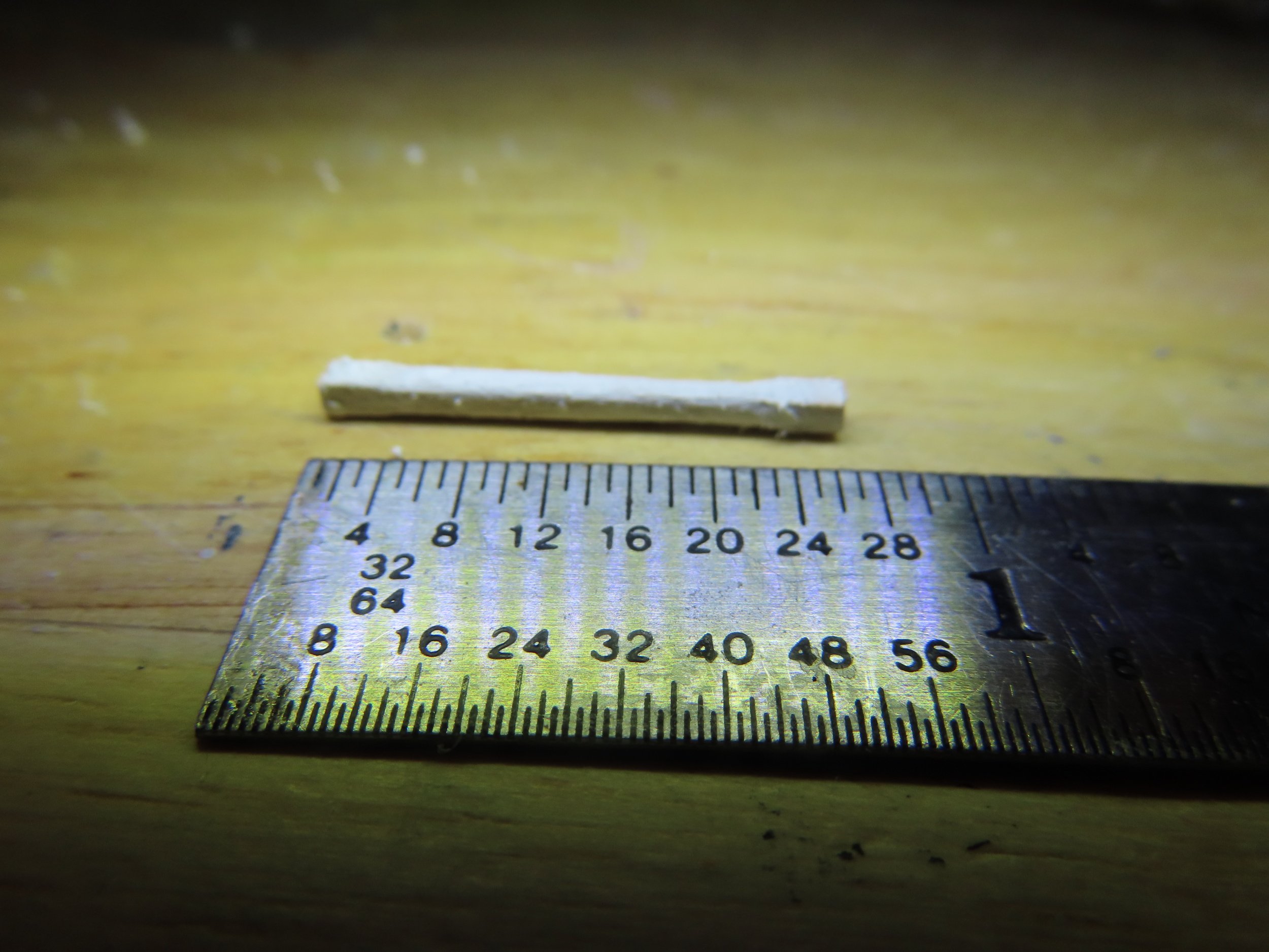
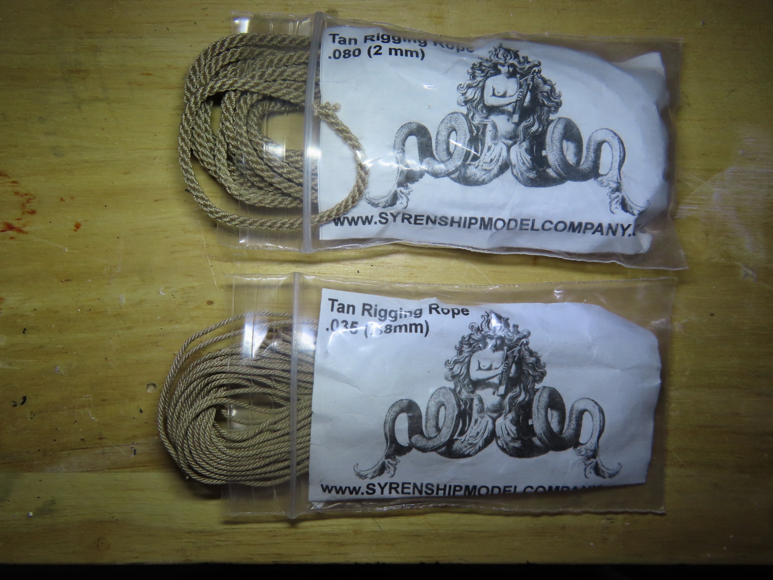
Determination of the Anchor Cable and Messenger Cable Size The question arose: what size is the messenger cable? First, I had to determine the size of the anchor cable. Step one as indicated below, I found on another builder’s log who was quoting one of the historical ship building books of old. Sorry, didn’t record that either. 1. “The Circumference of the anchor cable = 0.62 the Diameter of the mainmast” 2. Main Mast Diameter (US Navy plans) = 32” (full scale) 3. Anchor cable Circumference = 0.62 x 32” = 19.84” (0.258” scale) 4. Anchor cable Diameter = C/π = 0.258”/3.14159 = 0.082” 5. Guestimate that the messenger cable is ½ the Diameter of the Anchor Cable = 0.041” (3” full size) I could not find the rule for messenger cable size, so it was assumed the messenger cable diameter had to be small enough to wrap around the capstan and still be strong enough to pull either the cable or chain. In my stock, I have Syren Ship Model miniature tan rope sizes 0.080” and 0.035” for the anchor cable and messenger cable respectfully which should work for the model.


-
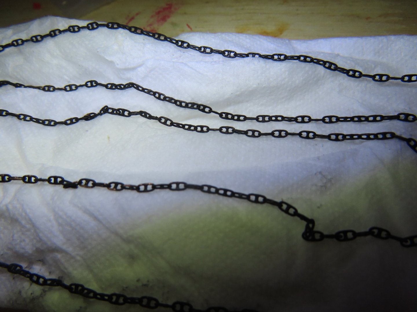
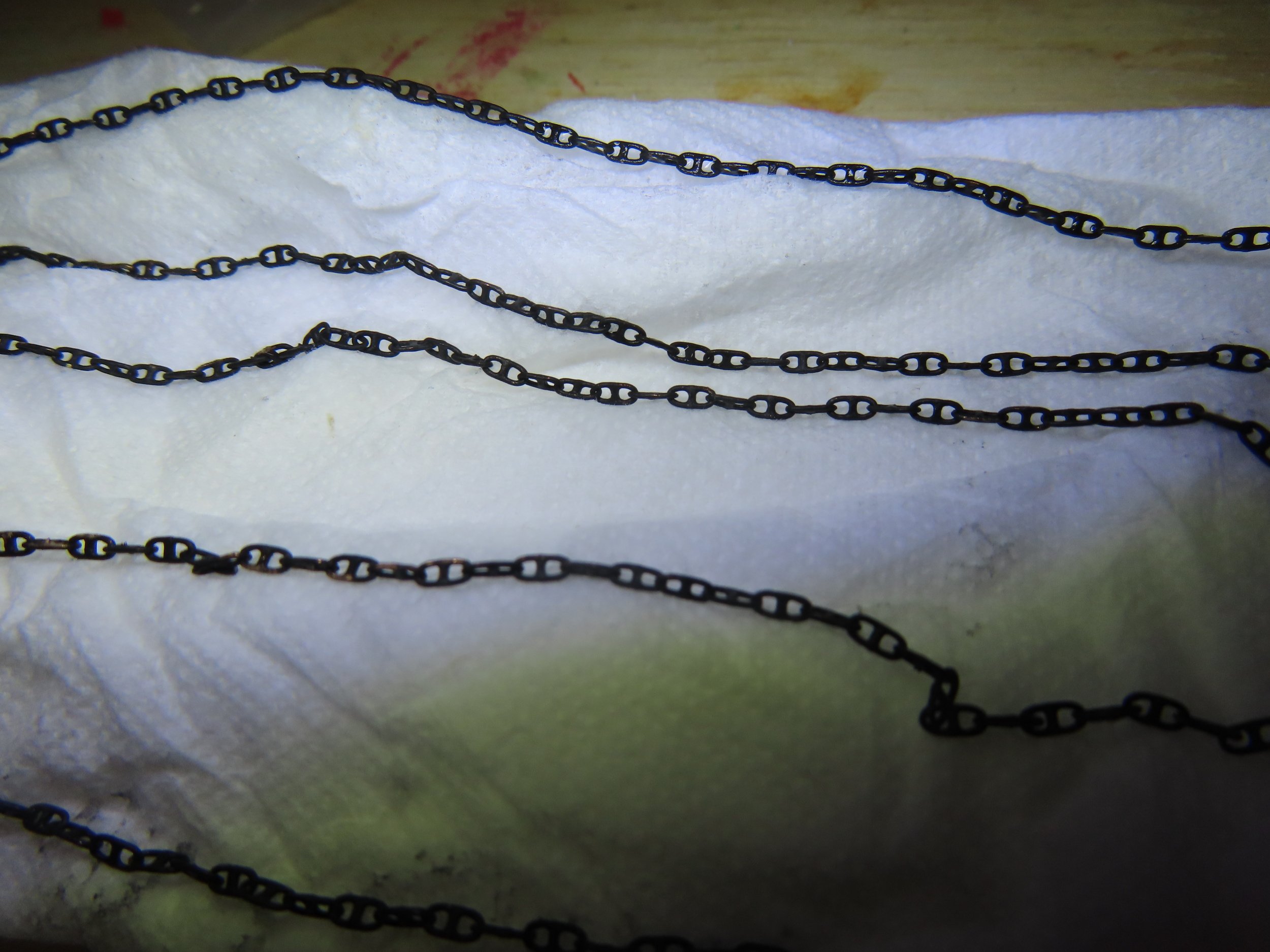
I ran into a couple of surprises that although I had thought about them before, I overlooked in the end. When the capstan is engaged, anything that would interfere with the capstan operation and anchor cable/chain are in the clear, like hatch covers are in place and ladders are stowed away. In my case, I fabricated the hand ropes and stanchions for the ladders going down to the berth deck next to the gun deck capstan. As built, they would interfere with the messenger cable wrapping around the capstan. Also, I forgot to create the ladders going up to the spar deck for the open capstan hatchway, which I took care of. One of the infamous Murphy’s Laws states: that no matter what you must do, you must do something else first. In this case I must install more supporting spar beams and their associated diagonal knees at the bulwarks as well as their support columns. But the more beams I install, the more difficult it becomes to install other items on the gun deck. Therefore, I’m constantly checking the sequence of fabrication and installation. While I’m doing this, I decided it was time to lay down an anchor cable and an anchor chain. There are three anchors that came with the MS kit. One will be attached to the anchor chain, the second one to the anchor cable, and the third will be stowed on the deck. The anchor chain that came with the kit has single links, but according to the photographs of the ship when she last used her anchor in the 1930s, she had a cross-linked chain. Today those chains are being used for mooring. I bought such a chain off the internet a year or so ago and unfortunately neglected to record where I purchased it from. The chain metal appears to be copper which required that it be blackened. The picture below shows the chain after it was blackened and drying.