JSGerson
-
Posts
2,633 -
Joined
-
Last visited
Content Type
Profiles
Forums
Gallery
Events
Everything posted by JSGerson
-
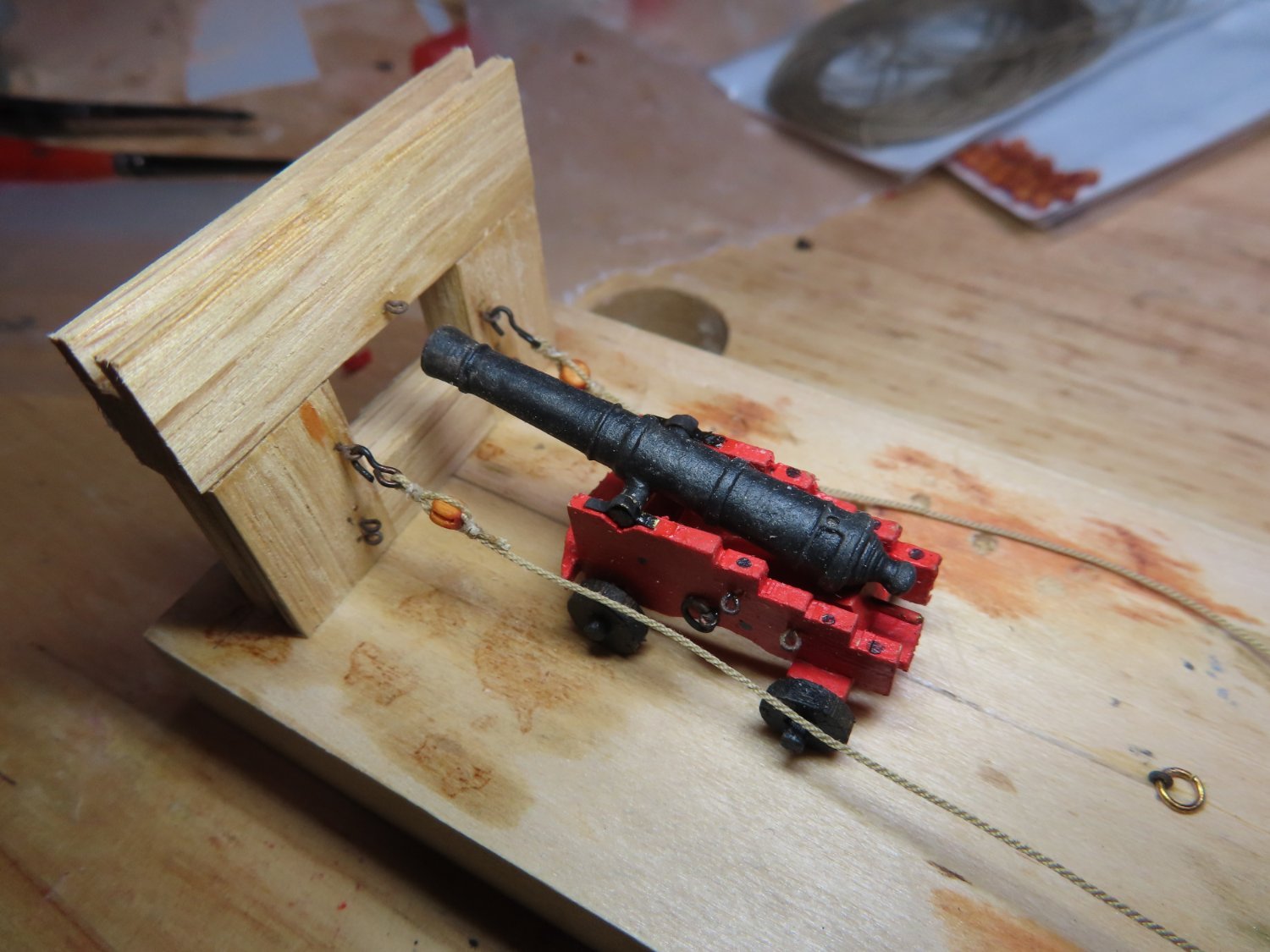
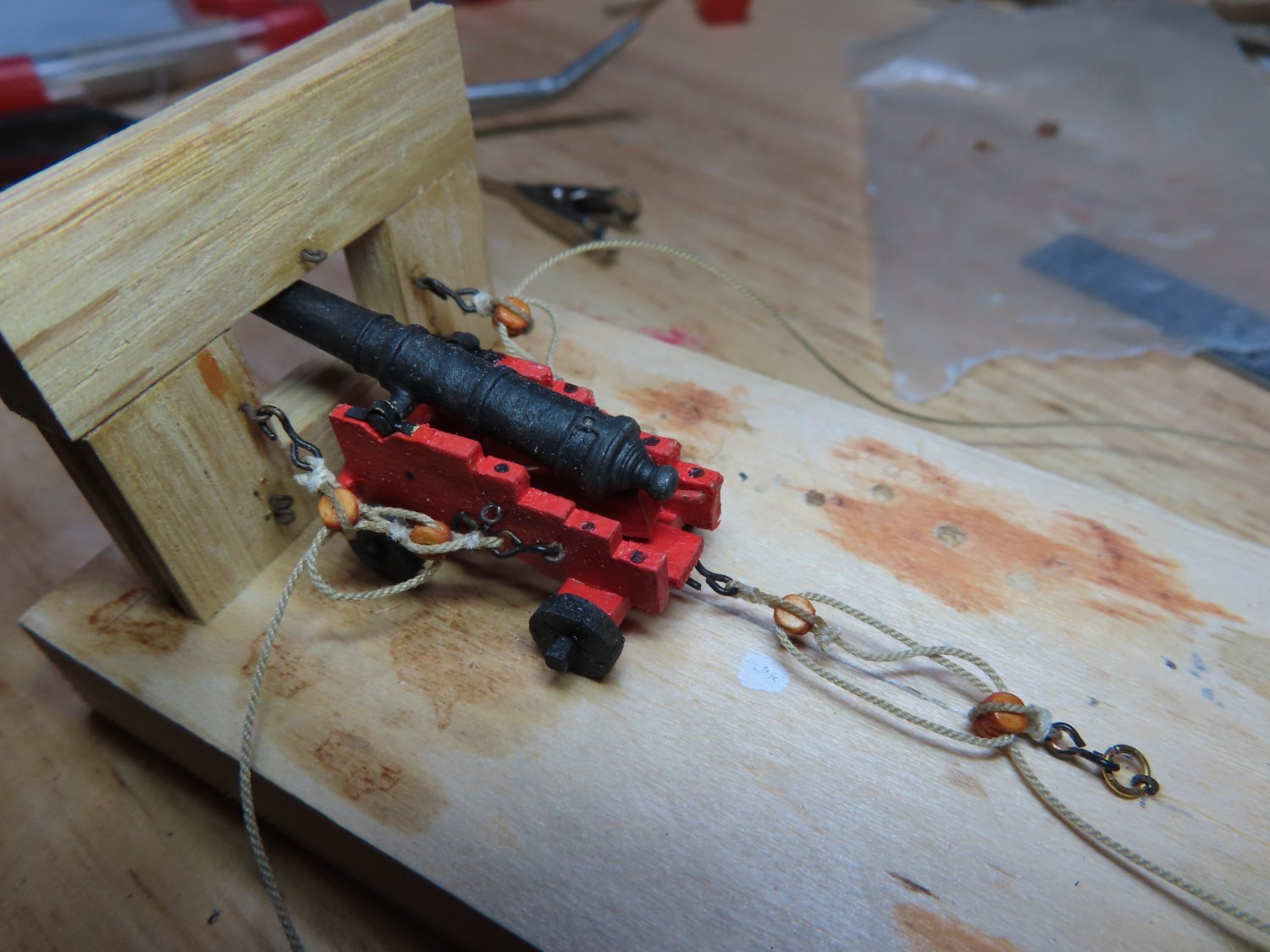
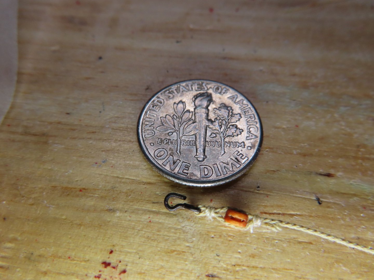
 Initially I had difficulty threading the rope through the block sheaves. I’m pretty certain that the holes that were originally drilled into the Syren blocks were of the correct size for the scale, but the scale rope was definitely not going to fit. I first re-drilled the holes to match the size of the rope diameter. Then I applied CA glue to the tip of the rope to hardenite it into a needle point. I eventually got one rope through the single block sheave, but it took a lot of time, patience, and tenacity. So, I increased the sheave holes size twice more before I got a reasonable result. The holes may not be to scale, but no one will notice. In the first picture below, the 3/32 single blocks were for illustration purposes hooked to the bulwarks but eventually were attached to the carriage and the double blocks to the bulwark in the second image.

-
The blocks were stained with Minwax Gunstock 231, then the hooks were attached to blocks. Because of the small scale, wrapping the miniature rope around the block and seizing it was slow.
-
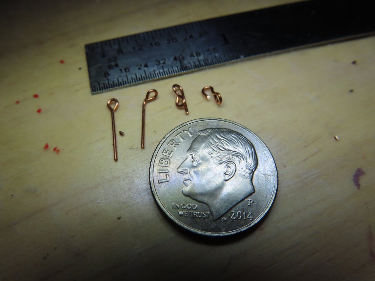
I took Usetosail’s suggestion and used the 1/32” eyebolts to make the hooks so they look like mtbediz’s results. They were then blackened (not shown).
-
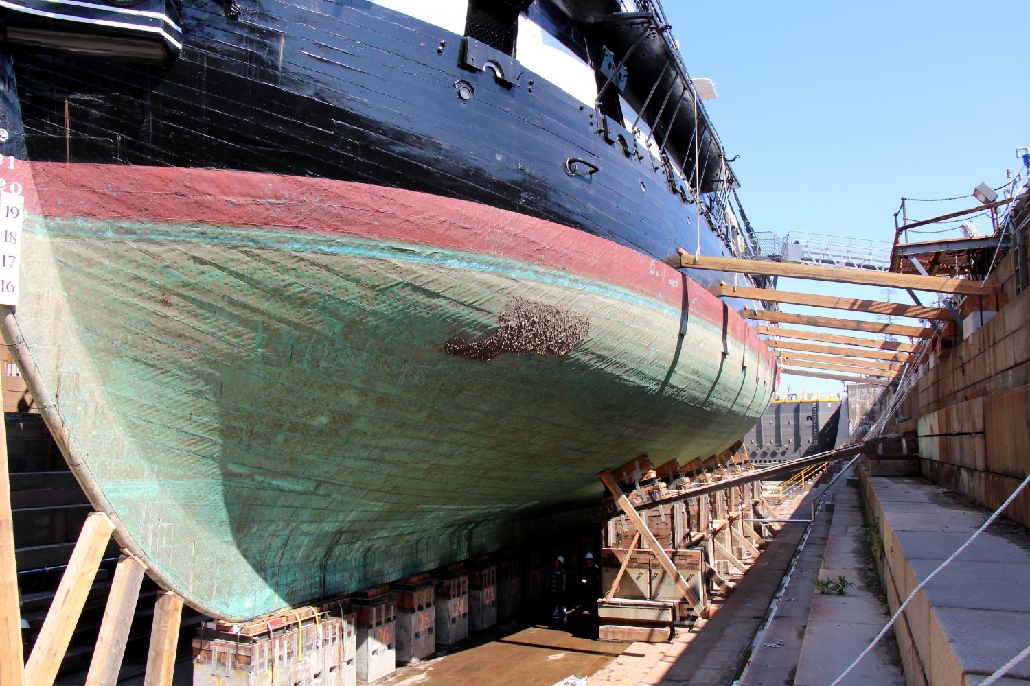
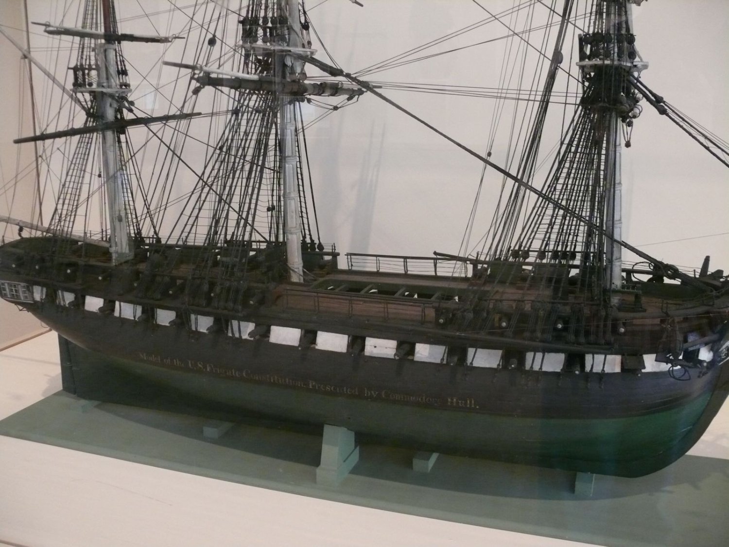
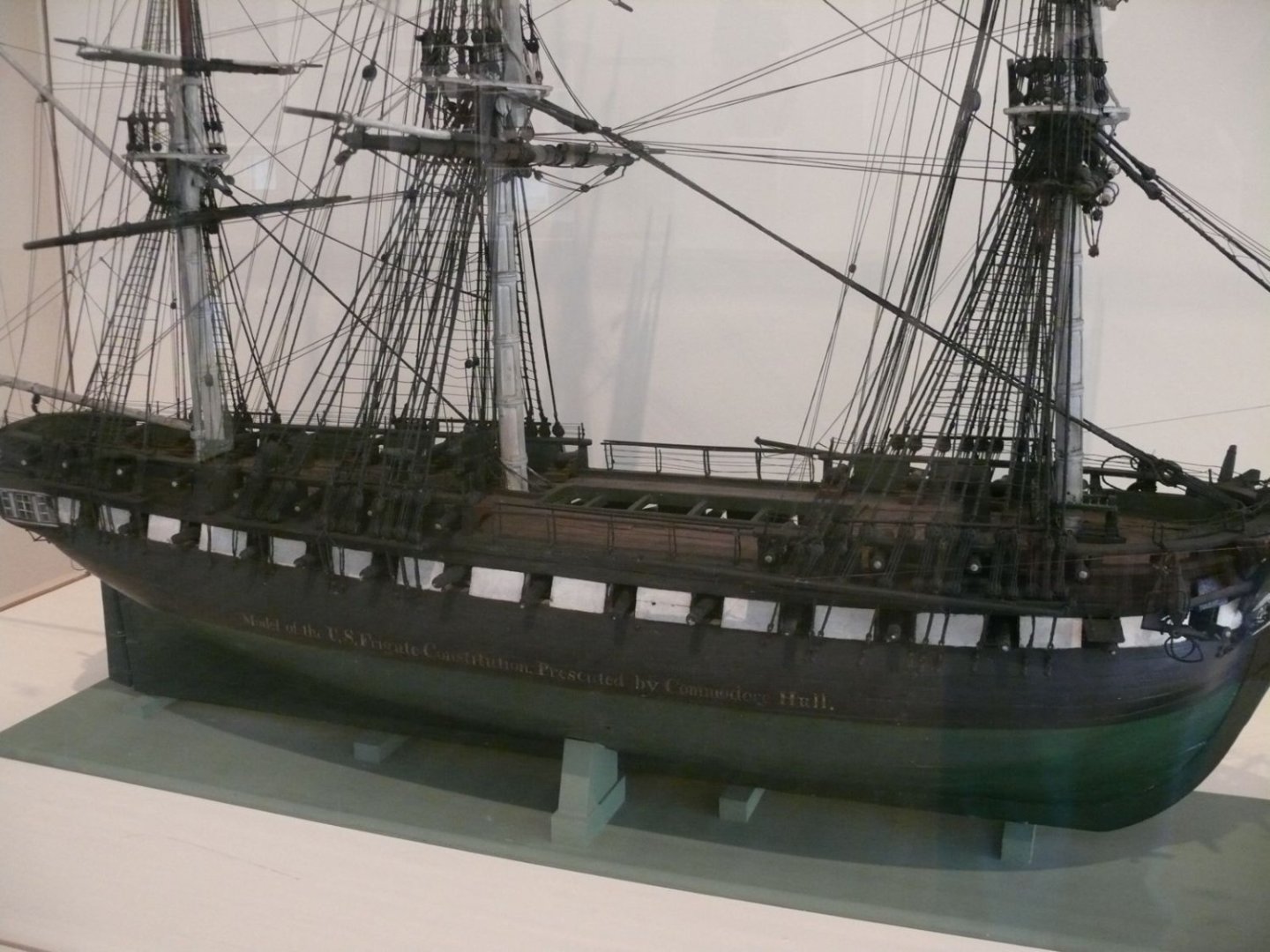
I expect my copper cladding to turn to the color of an old penny. If my model survives long enough, I expect it to turn green like the actual ship looks just before a restoration or the great Statue of Liberty. Even the 1812 Issacs Hull model had the hull painted green to represent the cladding. No disrespect to you, but to me, having it look bright and shiny is unrealistic unless you want the ship to look like it just came out of dry dock. Just my opinion for what its worth. Jon

-
Sounds like a plan Unegawahya, but since I would like 10-12 figurines, they got to be cheap. A custom printed figurine that costs $5 or so apiece would be about $50 or $60 for the group plus shipping which really more than I want to spend. My Rattlesnake (1:64 scale) has 6 figurines and that provided the visual scale for the 2-ft model but those figurines are too big this model (scale 1:76.8). The MS Conny is going to be 4-ft, so twice as many would be nice. Jon
-
When I get there, I'll probably modify the 3D parts as well. Now, if I could only find scale figurines to add to the eventual finished model to give the ship a sense of scale. I would like some period sailors about .75" tall (at a reasonable cost), but have had no success so far. Jon
-
Thanks for the 3-D printing site. I looked at their carronades and would have liked them better if the carriages were separate, but other than that, they looked fine. Jon
-
Good idea Tom! Jon
-
Der Alte Rentner: I didn't know I was a muse! I thought I was just an old fart😁
-
Mtbediz: Your hook style was what I was originally thinking of doing. It was just the sheer number of them that seemed daunting that I considered purchasing them. Hand crafted hooks might still be the way to go. I'm not certain that twisting flat plastic or PE hooks is worth the appearance or effort. Geoff: I agree with you 100%. You can't get bored with this build and I've been at it since 2017. Jon
-
Thanks for the possible solutions. I have some plastic ones to experiment on. I'll have to think about an easy, safe, effective, and efficient heat source. Jon
-
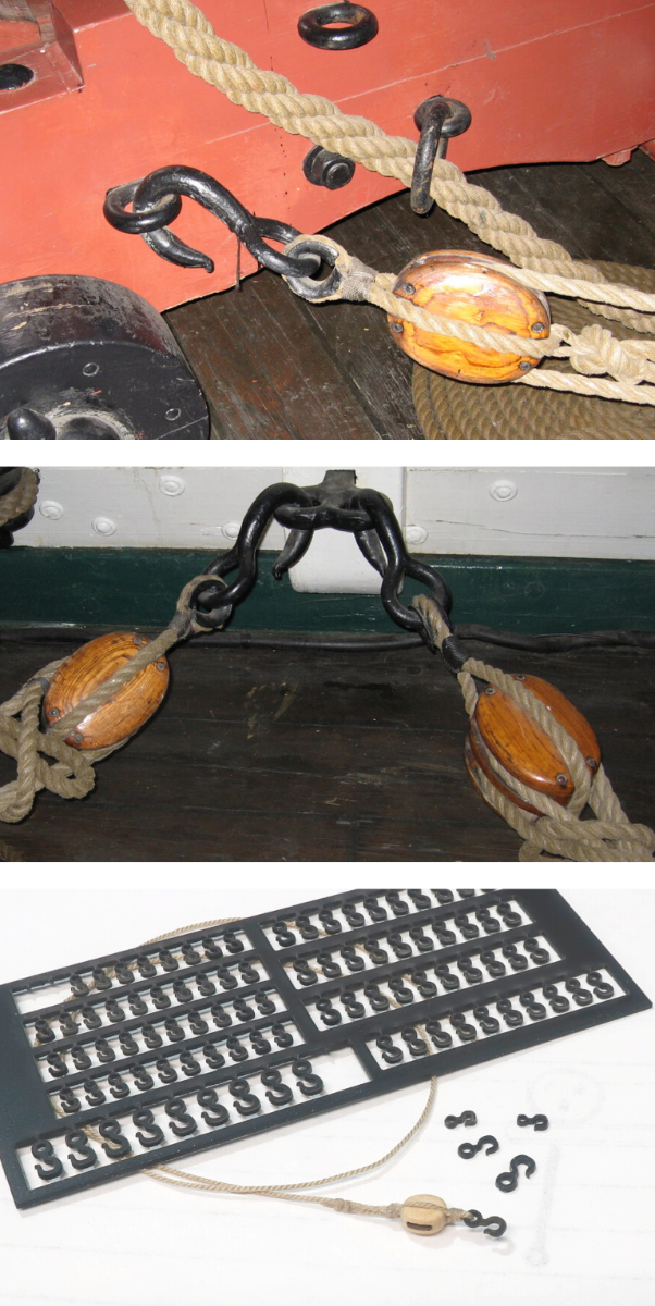
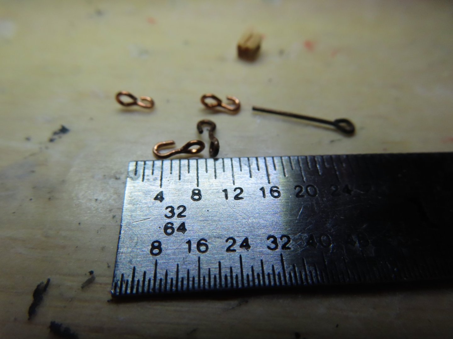
Things are going to get crowded on the gun deck. To install the guns, the anchor ropes and chain need to be installed first, as the guns’ tackle will lie on top of the anchor cables. Also, the structural elements such as the diagonal knees, stanchions, and spar deck beams and braces all need to be installed in concert as I move down the length of the gun deck. Don’t forget, all the gun deck furniture that was fabricated earlier needs to be installed as well. So, to start off simply, gun rigging also requires six hooks per gun which need to be either fabricated or purchased. Syren offers plastic hooks but unfortunately, there is a problem. The problem exists not only with Syren’s product, but with other manufactures as well, be it plastic or photo-etched. The eye of the hooks is parallel with the hook itself. In the picture below, you can see the actual hooks have the eye turned at a right angle to the hook. It appears, I will have to fabricate at least 132 1/8” hooks just for the gun deck. I haven’t checked out what the kit has supplied for the spar deck. If anyone knows a cheap supply of properly formed hooks, I would be very interested.

-
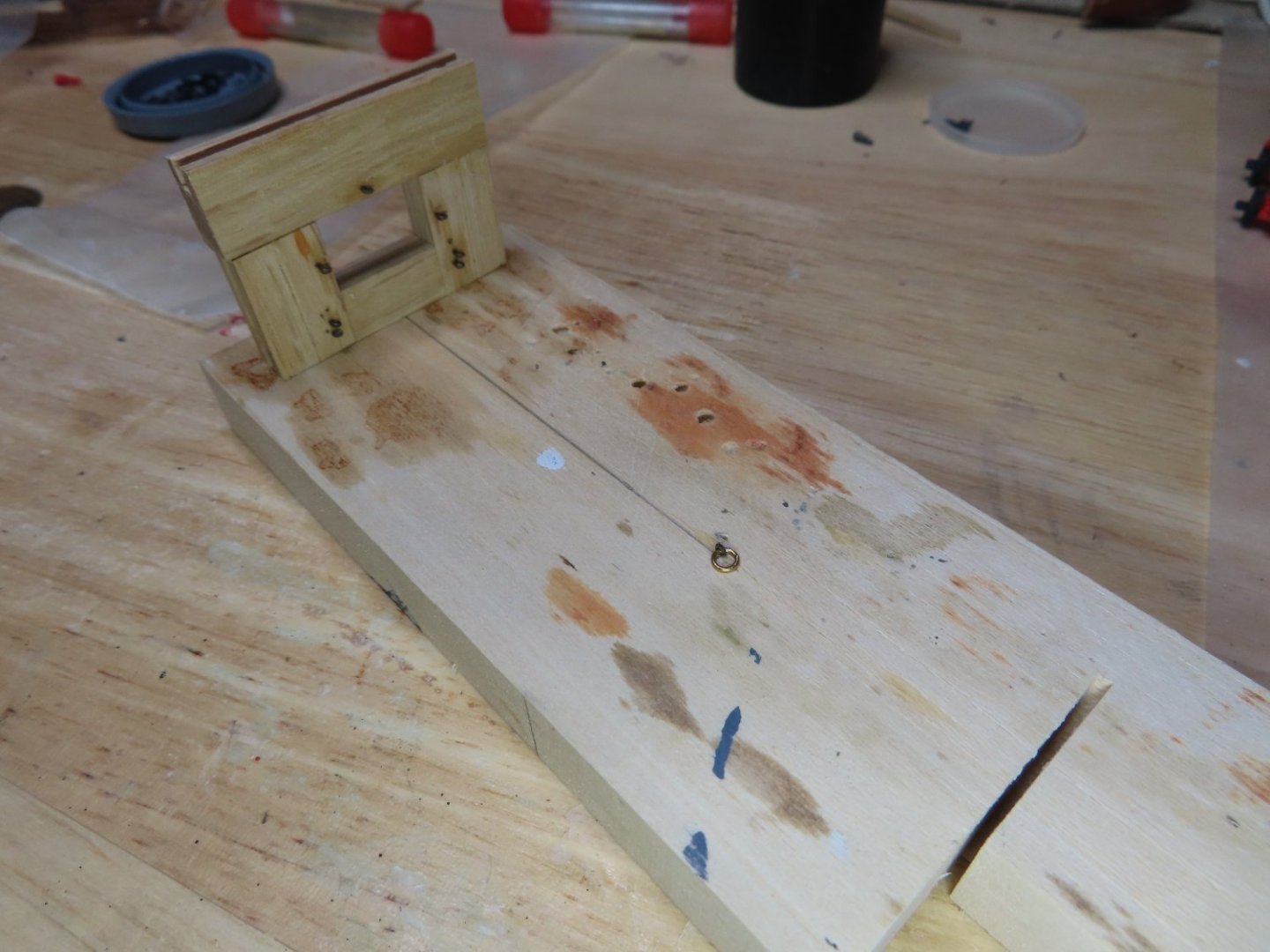
In preparation for the fabrication of the guns’ train tackle and breeching lines, a jig was made to facilitate the fabrication of those lines off-ship. Because the kit obviously does not have any supplies for the gun-deck guns’ rigging, 3/32” single blocks, 1/8” double blocks, 0.018” and 0.030” scale rope was ordered from Syren Ship Model Co. Those should arrive next week.
-
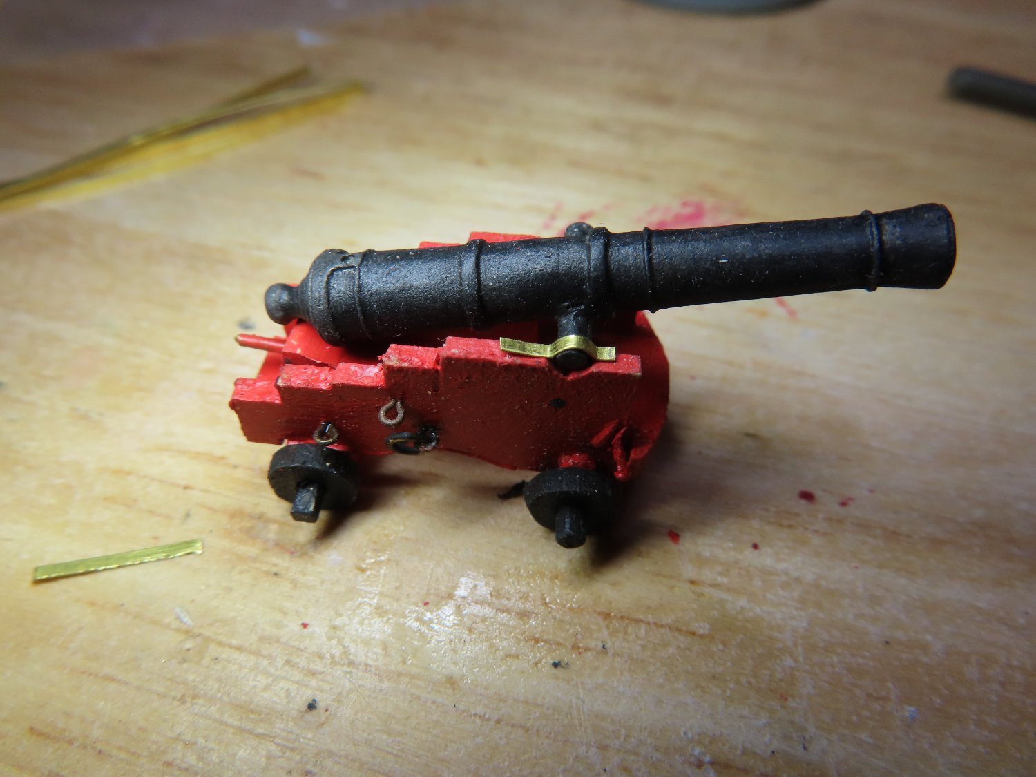
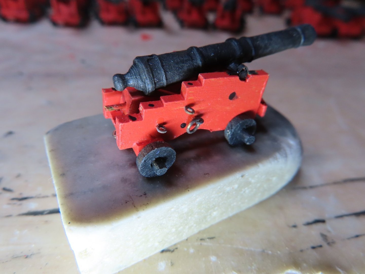
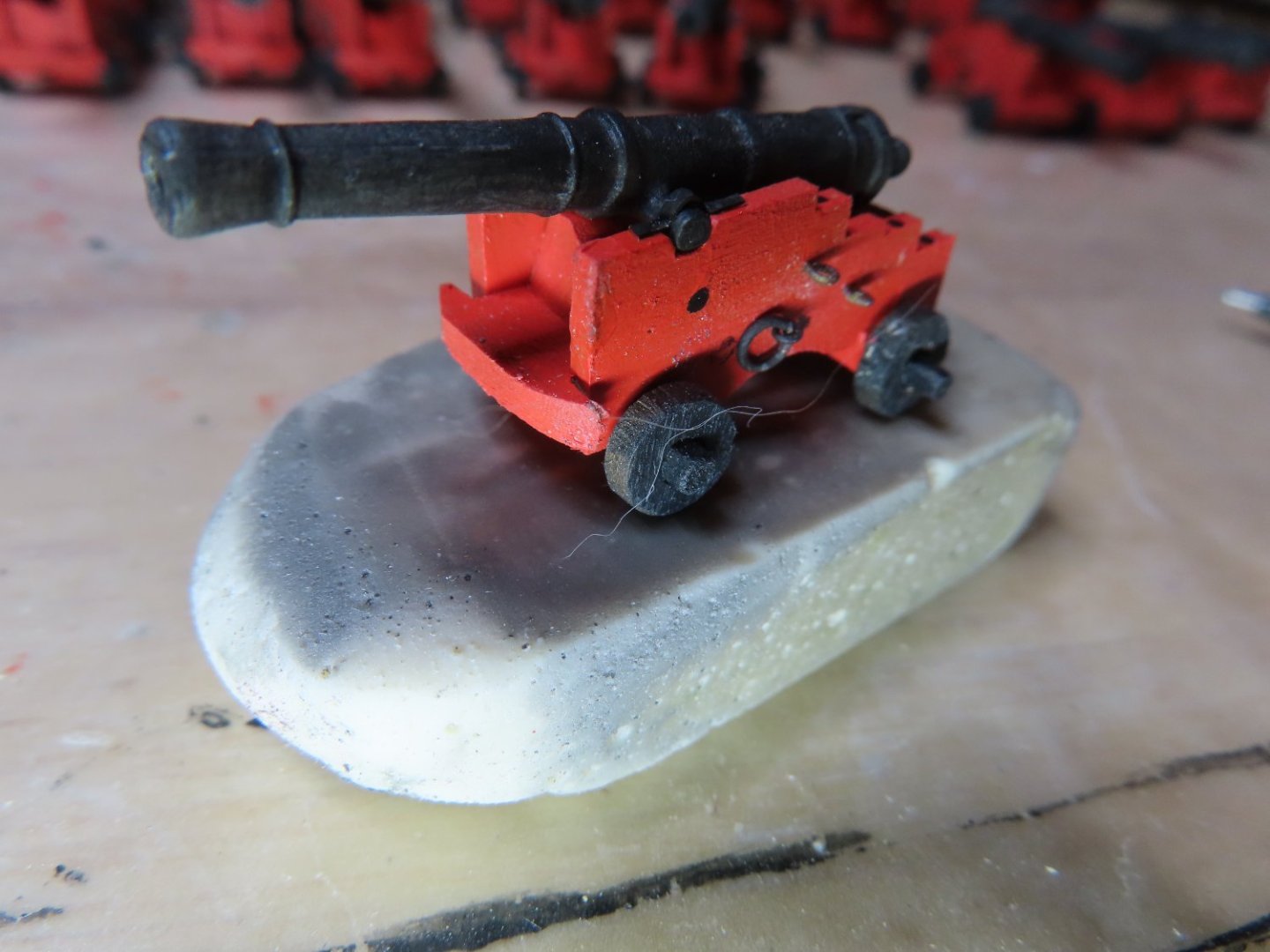
Jax Black arrived and seemed to work just like Blacken-It, so all the trunnion caps were blackened. They were fastened to the carriage with CA very carefully so that the barrel could still rotate for final adjustment when the guns are placed in their final positions. Due to their function, the quoins are not glued in place awaiting that final placement. In addition, black dots were painted on the carriages to represent the black bolts. At this scale and final viewing location, that’s all that is needed. When I looked back at the practicum for the spar deck, that is exactly what Mr. Hunt did for the cannonades’ bolts.
-
Helmar: I will definitely drop your name should I concede in my attempt to fabricate the companionways. Thanks for the info. Jon
-
Helmarsowick: Thanks for the info, I'm tempted. If I may ask, what/how does he charge? I've got the kit's and the US Navy plans. Be that as it may, I think before I do that, I would want to give it a shot myself following Ken's lead. I mean, it's the point of building a model. I just need to know my skill limits. Jon
-
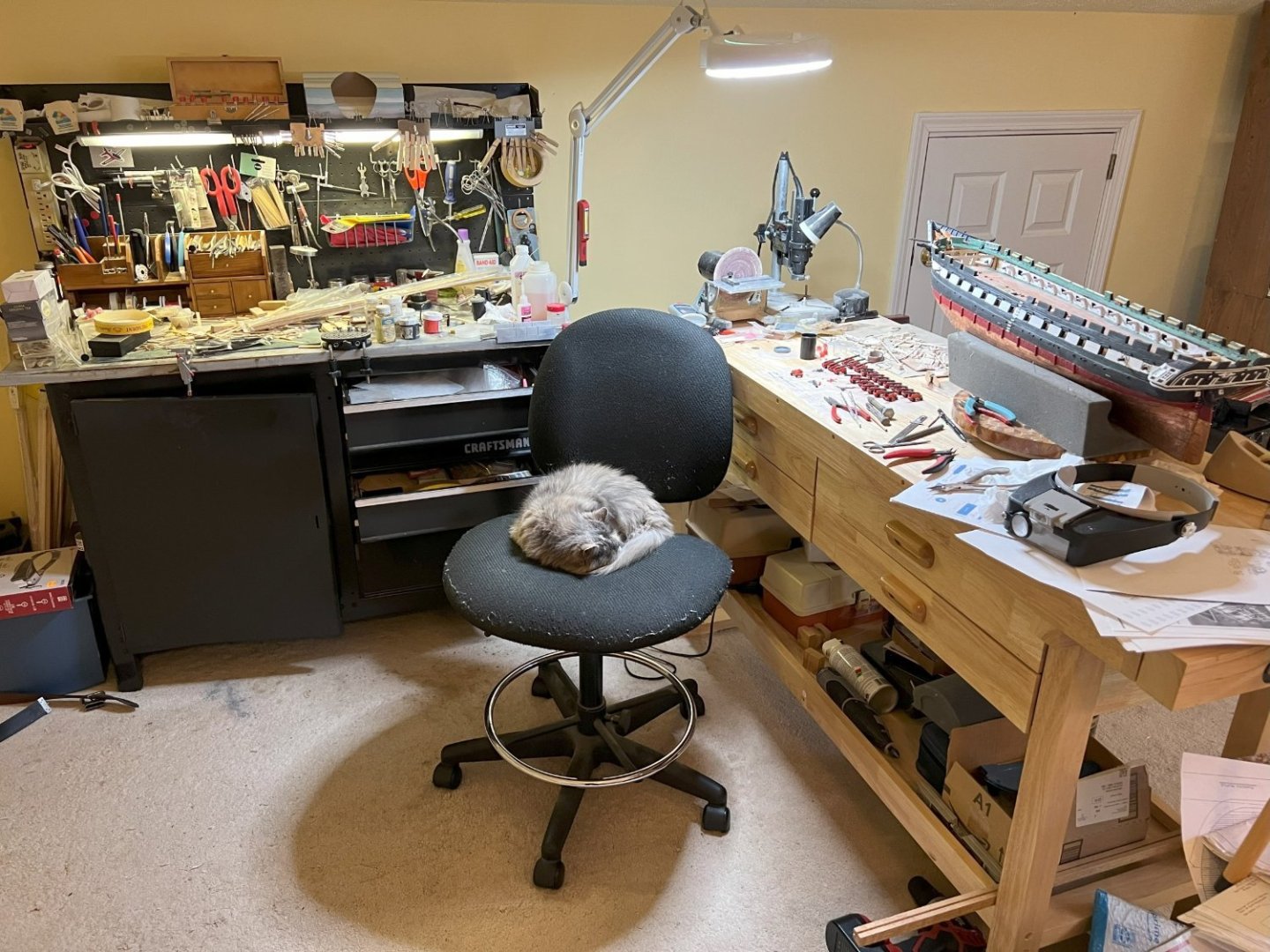
GGibson: The lazy susan was made as a mosaic pattern with blocks of wood by my uncle. I inherited it in 2020 and found it quite useful. The only "problem" is that I would like to be able to lock it in a fixed position at times, but haven't spent much time figuring out a solution yet. BTW, Peaches is a she and is 14 yrs old. Not once has she ever touched my work benches. She's a really good girl. Helmarsowick: Those companionways you made are glorious. There a number of them on the Constitution that I will have to fabricate and plan to follow xKen's (Ken Forman) build log for them. He silver soldered his. He designed the cross section kit of the Constitution for Model Shipways. I think you put are giving him a run for the money. Is that one solid piece straight out of 3D printer?
-
Helmarsowick, that's basically what I did for the Rattlesnake. I got the unassembled unfinished case from Model Expo and the table from another online source. I had to cut the vertical corners to size and buy the plexiglass. The table was complete, no work to complete. Still, it wasn't cheap; and this model is twice as big as the Rattlesnake! But, I can put it off for a while at the rate I'm building the model. See picture below for one of the reasons I'm so slow Jon
-
GGibson: I'm anxious too! Geoff: Not only do we have to encase this baby, but I'll need to buy a table to put the case on (see my Rattlesnake), and find a space in my house to display it. Since I don't have any normal sized wood working tools or the cabinetmaking experience/skills in using them even if I had them, I'll have to buy a custom case or pay someone to make the case for me. Any way I look at it, it's going to cost a bit of money. Jon
-
I've kit bashed my build by adding the gun deck. I now am in the process of fabricating 22 gun carriages (I've already have eight dummy guns) and still have to rig them all. I will be doing a complete carriage rig so, I understand how you feel. Jon
-
Good to have you back. I look forward to your future posts. Jon
-
When I tried to blacken the caps, I realized that the last of my Blacken-it solution had lost its potency. It seems that the company that made the stuff is no longer in business. So, I must wait until my order of Jax Black arrives. I’ve never used this product, so we’ll see how it goes. In the meantime, I’ll be adding all of the eyebolts and rings to the remaining 21 gun carriages. In the image below, the cap is dry fitted and unblacken.

-
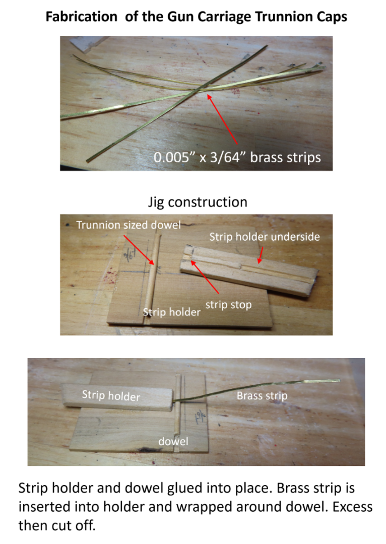
Gun Carriage Eyebolts, Rings, and Trunnion Caps Gun carriages have several eyebolts and rings to facilitate the movement of the gun assembly during firing and positioning. In numerous builds I’ve seen posted, it appeared to me that the eyebolts used on their gun carriage were way out of scale – much too large. Relative to those, mine may appear too small to many viewers. Using the US Navy plans for the 24” pdr. gun carriage as my guide, it shows for each carriage side, three horizontal eyebolts at approximate 1½” ID or (0.02”) 1/64” at scale. Making that size eyebolt is nearly impossible (for me) and not practical, so I’m using 1/32” eyebolts. These I have purchased from Model Expo and used over the years. One of the eyebolts has a 2½” ID or (0.036”) 1/32” at scale ring attached. To maintain the illusion of size difference, I used a 3/64” ring. The eyebolts on the forward and aft axials are 1¾” or (0.023) 1/32” at scale. Again, to maintain the illusion of size difference, I used a 3/64” eyebolt. In lieu of black paint, the hardware was blackened. The trunnion caps although simple in construction, were a little trickier to handle and form due to their size. I made mine 3/64” wide by approximately ¼” raw length. It shortens up when shaped around the trunnions. To facilitate its fabrication, 0.005” thick brass plate was cut into 3/64” strips using the Byrnes saw. These strips were fitted into a simple jig to form their cap shape. The jig basically held down one end of the strip at fixed length, while the remainder was pressed over an equivalent trunnion diameter dowel. Then the opposite end of the cap snipped off the remaining length of the strip.
-
I re-read your build log because you have long surpassed me and now I’m following you. It was then I realized that you did not use the cannons or cannonades that came with the kit, but purchased them. You also purchased the ships stove which I tried to recreate from scratch. Where did you get them from? Once I get to the spar deck, I plan on modifying or replacing the kit’s cannonades so that it reflects the actual cannonades used in 1812. The present ones are incorrect replicas except for the two that use a screw to adjust elevation. I’ll have to scratch build all the carriages as well. You did a beautiful job. Jon
-
Greg, that is a lot of reading; I impressed. Thank you for looking in. Jon