JSGerson
-
Posts
2,635 -
Joined
-
Last visited
Content Type
Profiles
Forums
Gallery
Events
Everything posted by JSGerson
-

USS Constitution by mtbediz - 1:76
JSGerson replied to mtbediz's topic in - Build logs for subjects built 1751 - 1800
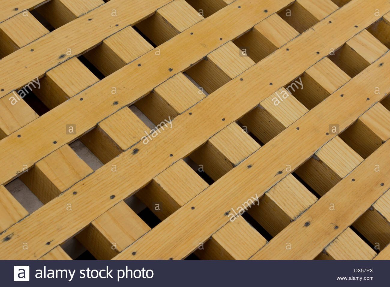
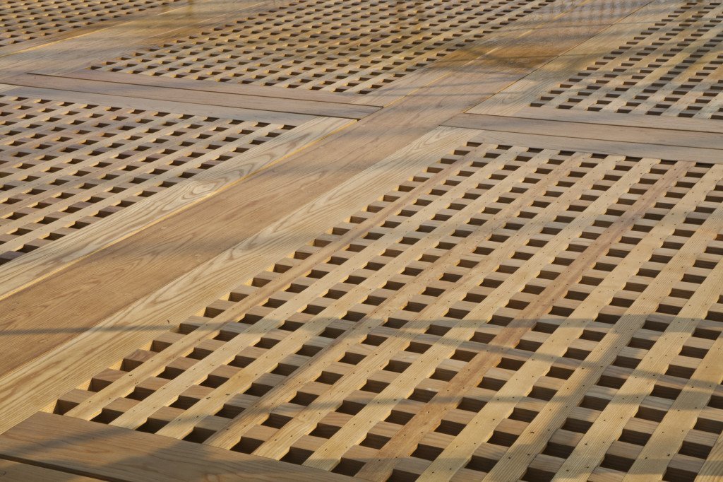
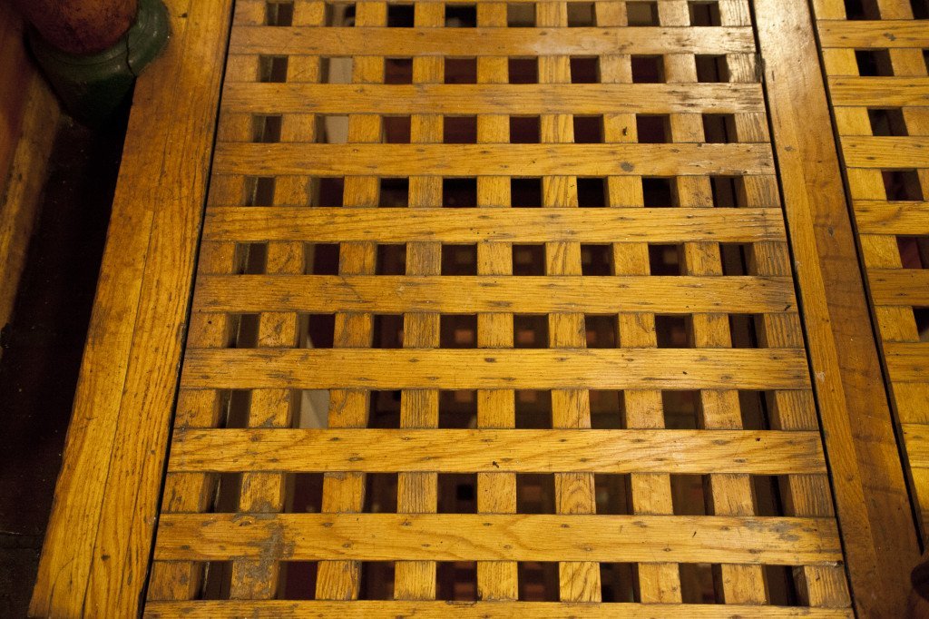
Beautifully done gratings. They look exactly like the real thing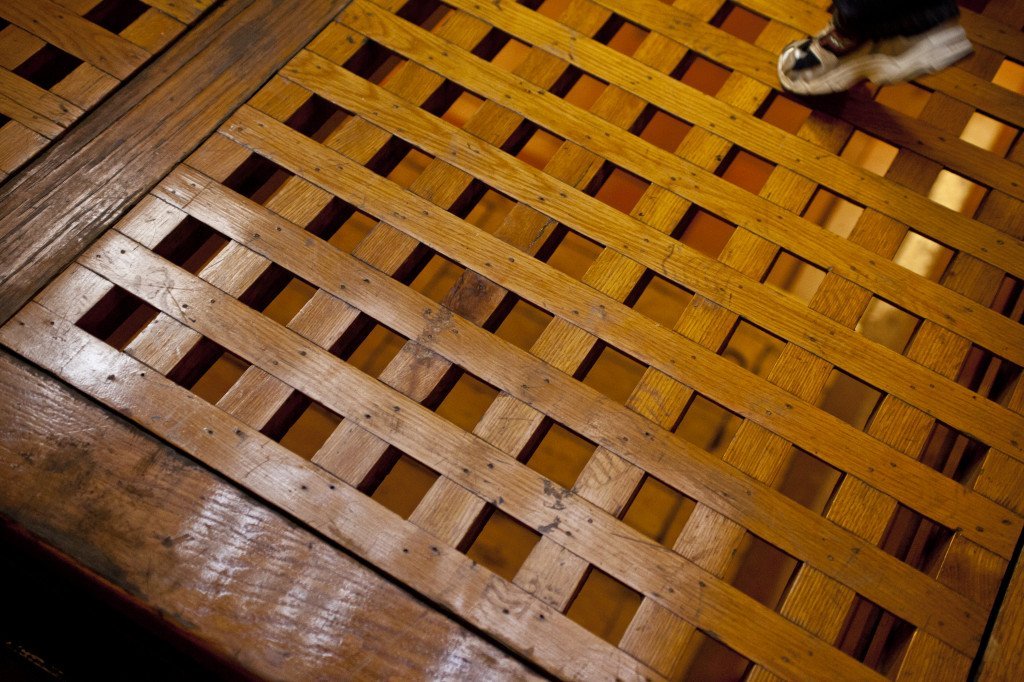
-
Like you. I did a lot of research and as you read my log, you will find that I rely a lot on the US Navy plans which you can still download for free from the US Constitution Museum. The collection of plans is not complete and range in dates from the 1800s to recent times. The MS kit is based on the 1927 restoration so if you follow the kit faithfully, it won't look exactly like it is today after the 2017 restoration, which what I'm making. Also I've built up an extensive library of images (approx. 4,000) so if you need a view or a "better" view of something, there is a good chance I may be able to help. I write my log in Word as well, but crop, group, and annotate images in PowerPoint. I group the final picture if there are multiple images, then "save as picture" as a png file. The text is simply copy and paste straight from Word into the online log. Mr. Hunt is an excellent builder but he has his quirks. I followed him fatefully for my first square rigger, the Rattlesnake and found that as I progressed into the practicum, he started to cut corners or did not address certain details. He stated that he is the first to admit that his way may or may not be the best way to do something. His practicums are like a diary written in real time, so if he makes a mistake, you will make the same mistake until he tells you oops, have to do this over later in his instructions. If something is not clear, check other builds to see how well they handled the problem. I am using him as a suggested guide for my Conny. As you read my log, I inform the reader when I'm deviating from the practicum and why. Two big deviations are I am adding the gun deck interior (scratch built) and have removed the topgallant rail (the one above the top rail) which was added in1927 but found to be not accurate to the ship so it was removed in the 1970s I think. The ship is a chameleon and changes its look over time, so if you haven't decided what era your model is representing, now is the time to choose. Jonathan
-
I just discovered your build log in the past couple of weeks due to your comments on UsedtoSail's log. As I started to read your log, it seems you found me first, crediting me with pointing you to Mr. Robert Hunt's practicum. You had listed a number of build logs that you were following, but I was surprised you did not list (or maybe you haven't discovered) Ken Forman's (xKen) build log. Ken is a professional model maker and kit designer. He designed the Model Shipway's USS Constitution Cross Section model. His is a worthy log to read. I am curious though, are you posting on two build logs? I ask this because your posts on this site are pdf files from another document. You are the first one I've run into using pdf files. I mirror my ModelShipWorld posts on ModelShipBuilder. Looking forward to your future posts. Jonathan
-
See if the attached US Navy file helps Jon 4513172a - Fore, Main & Mizzen Rigging Channels.pdf
-
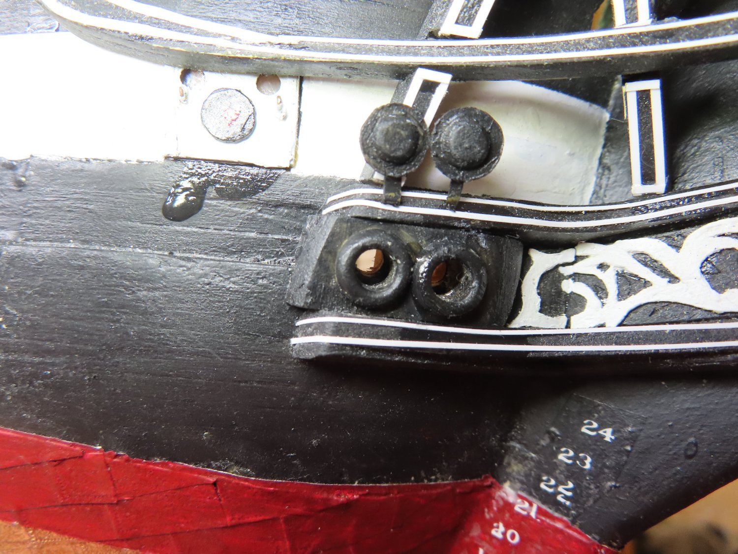
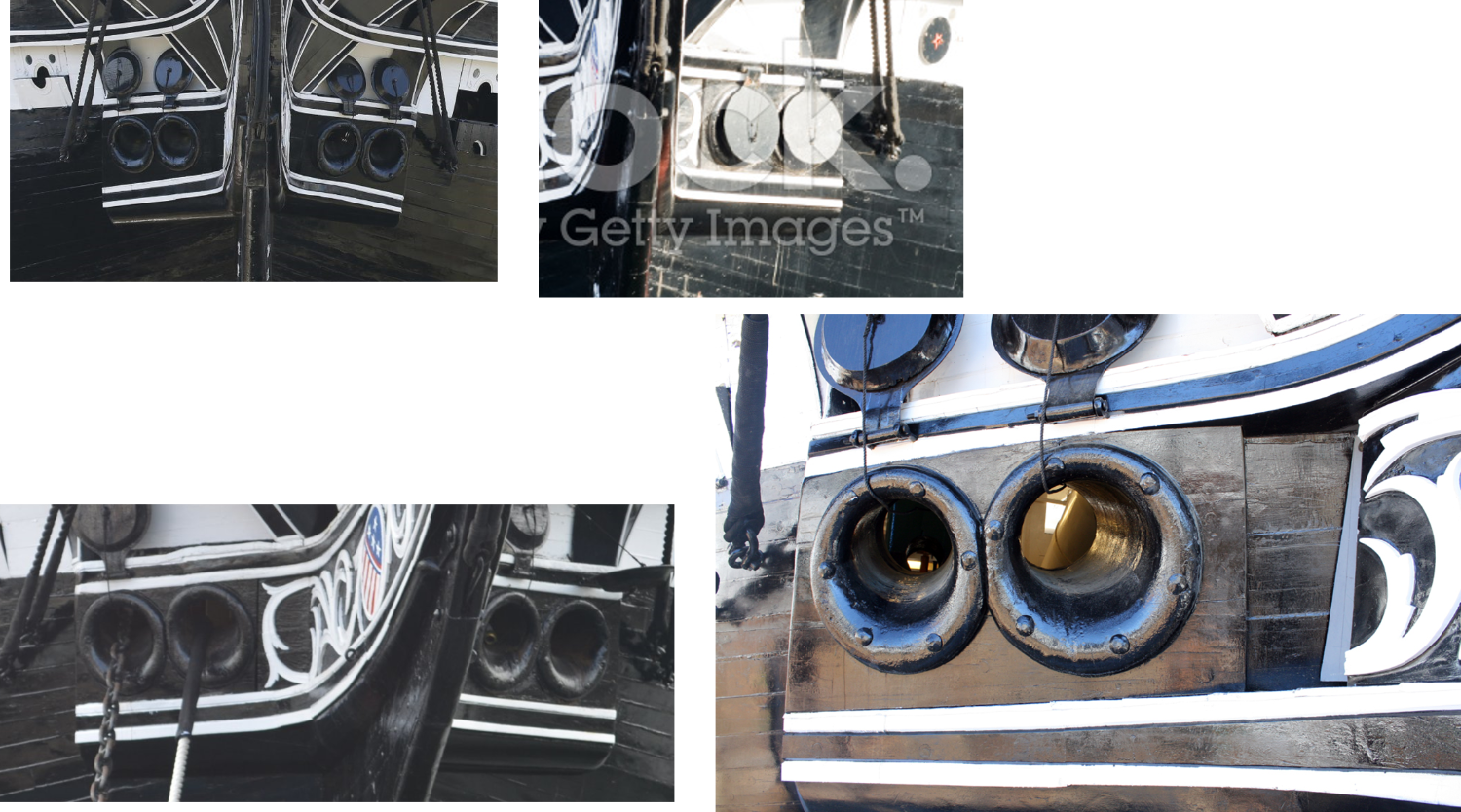
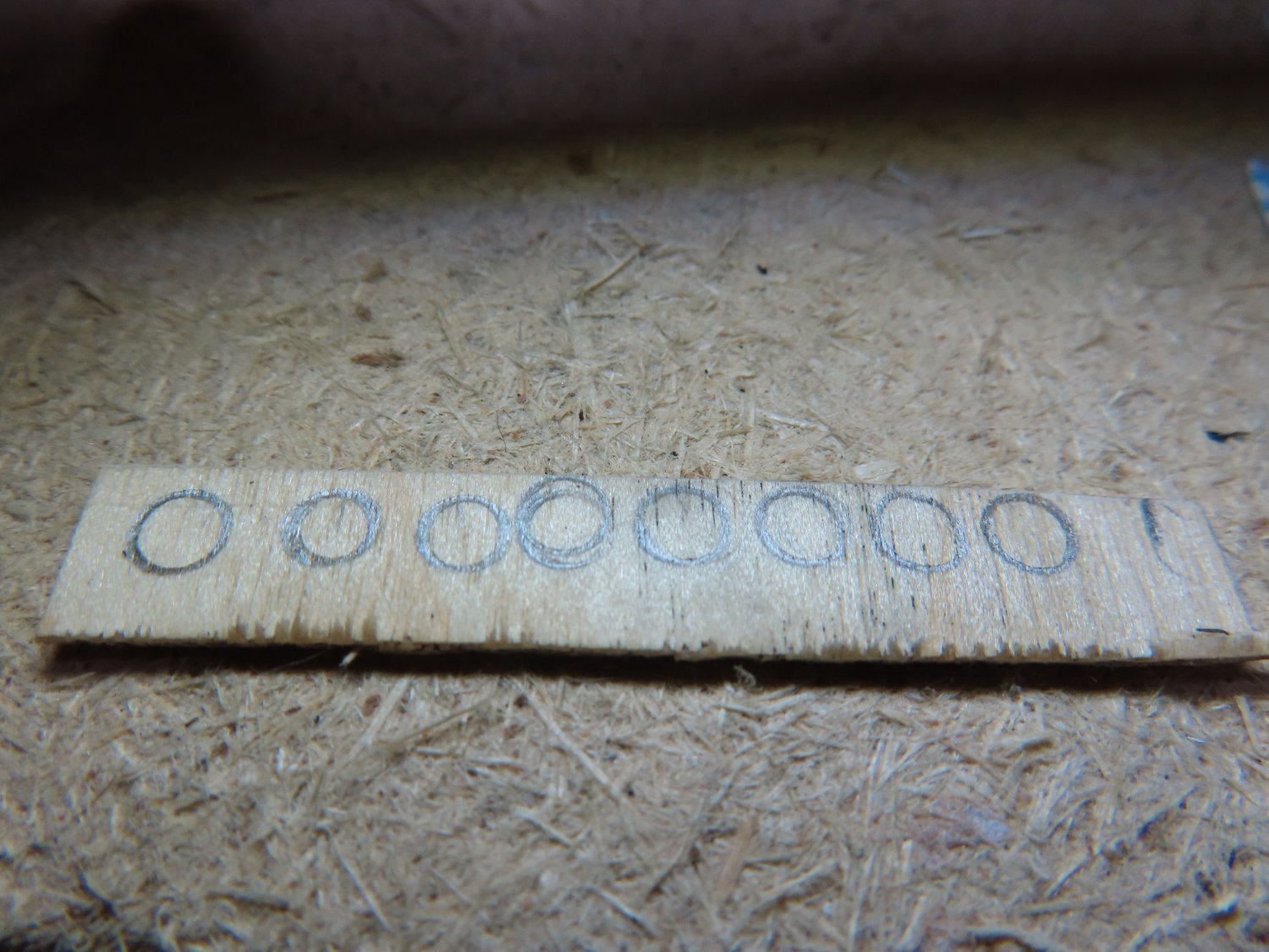
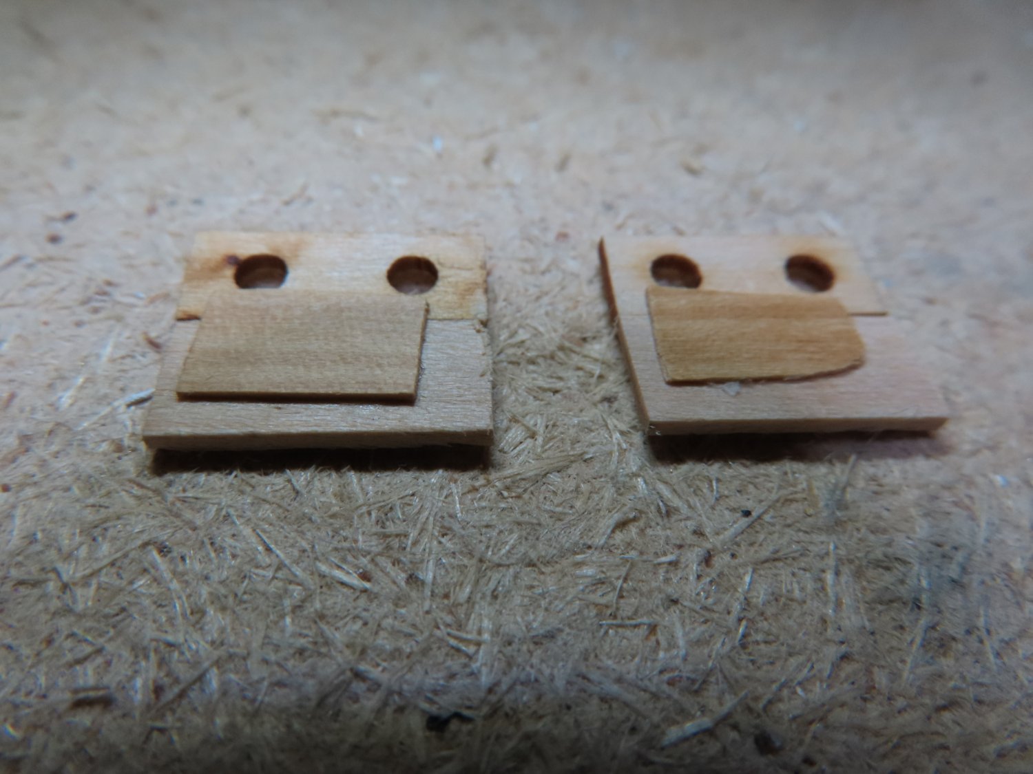
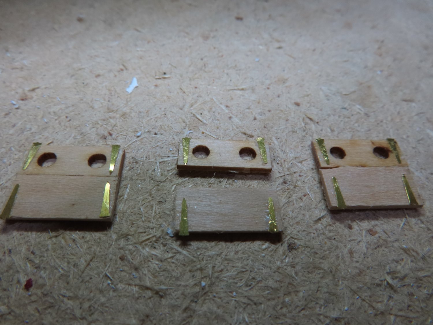
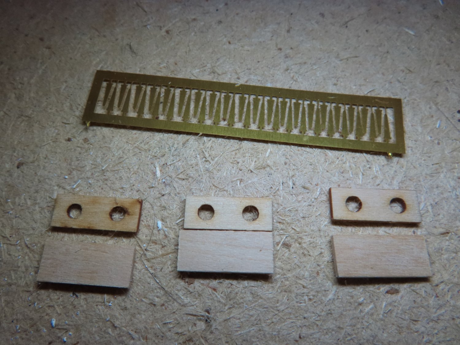
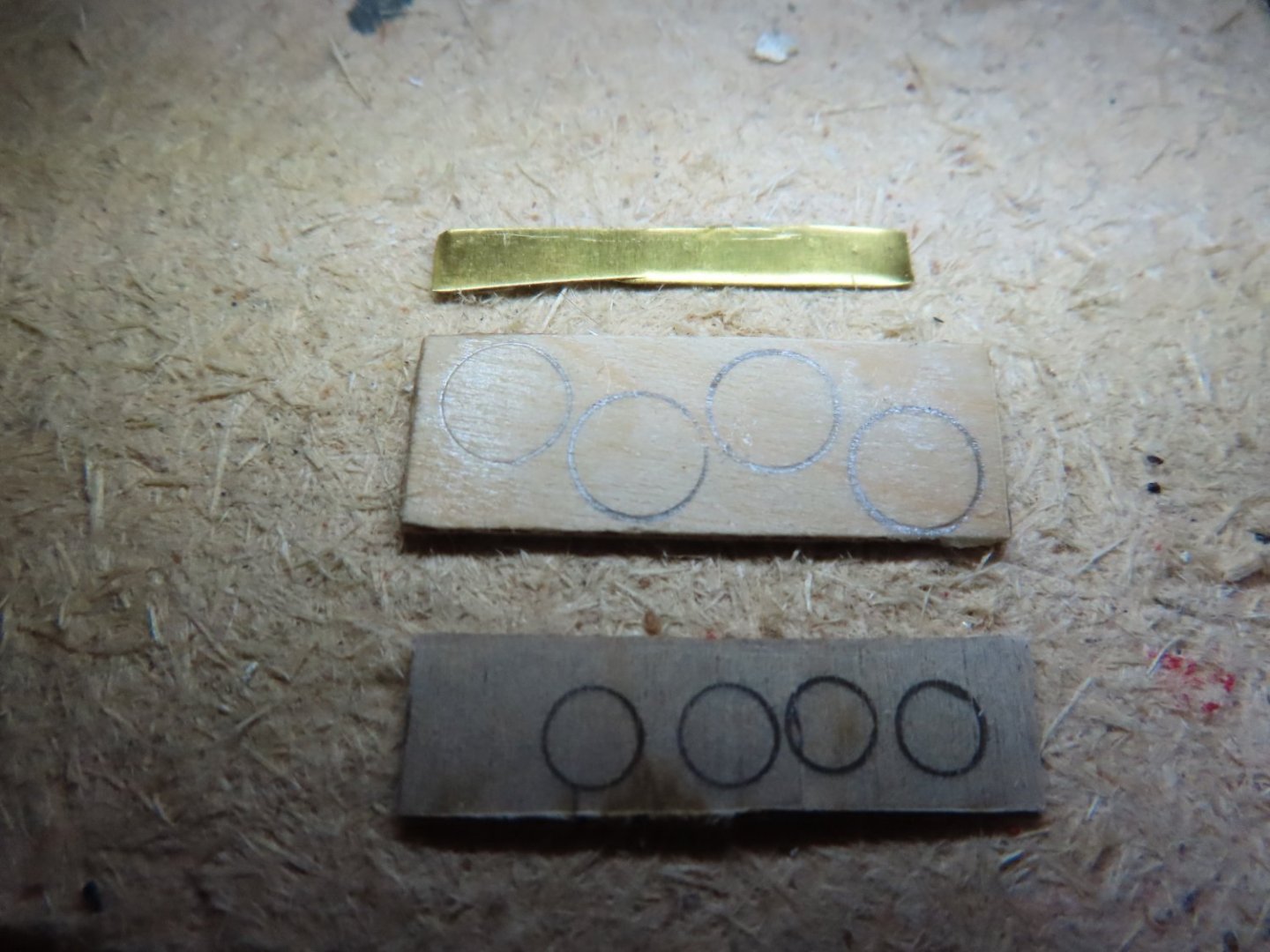
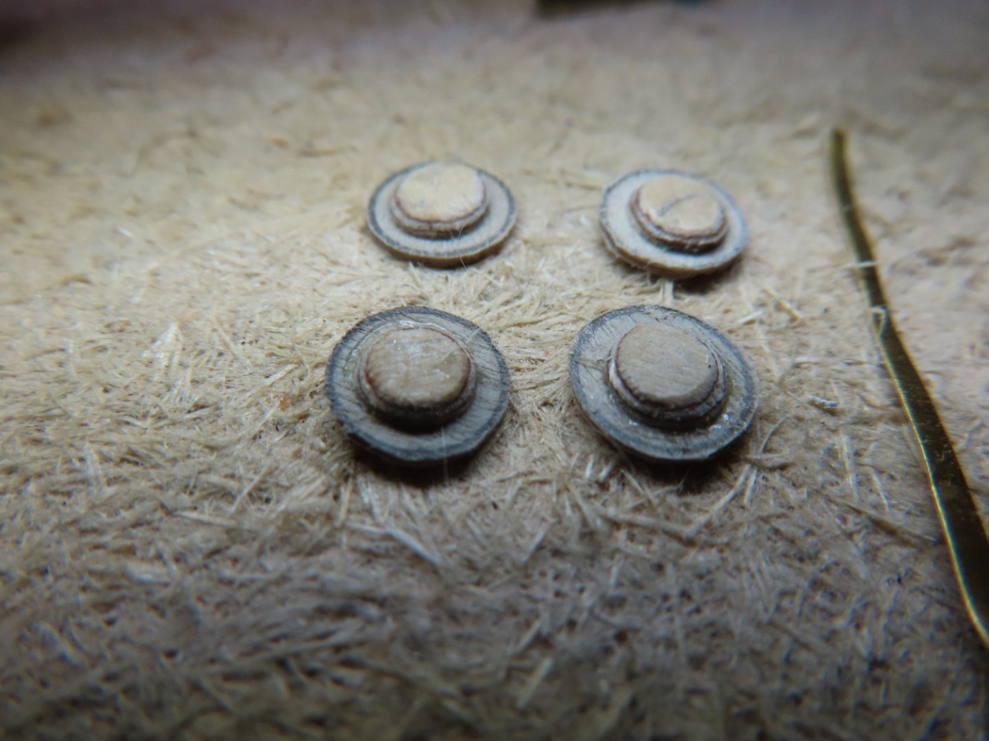
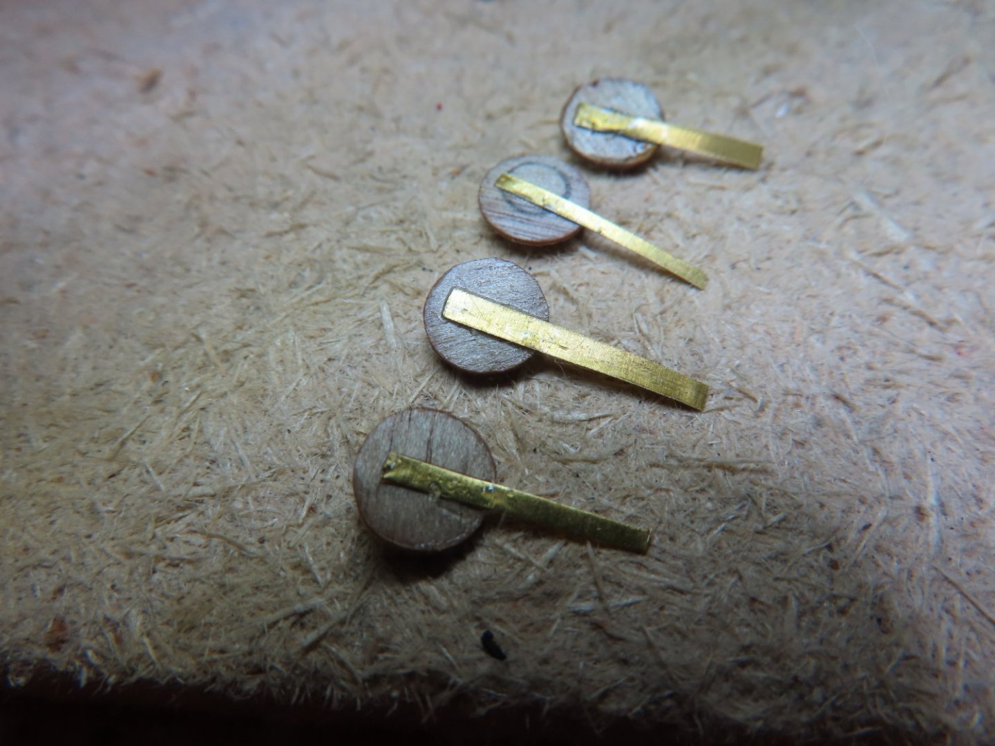
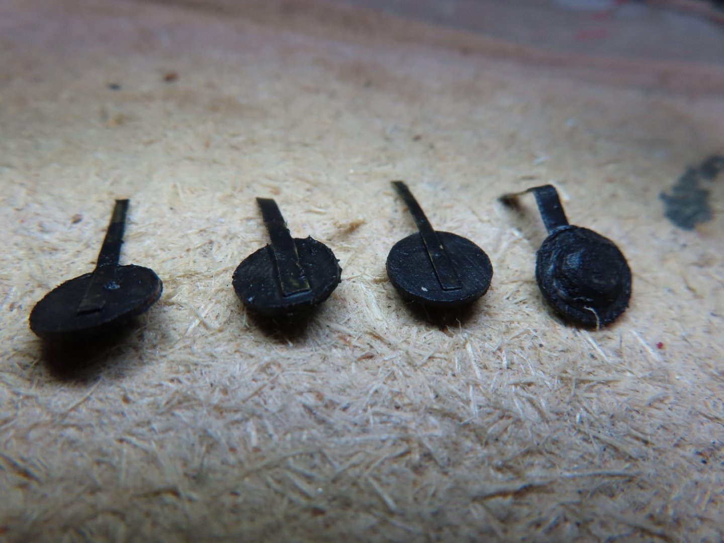
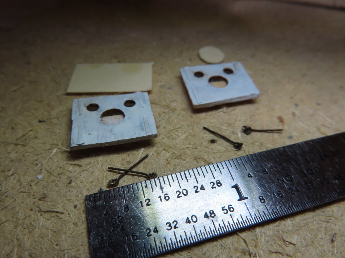
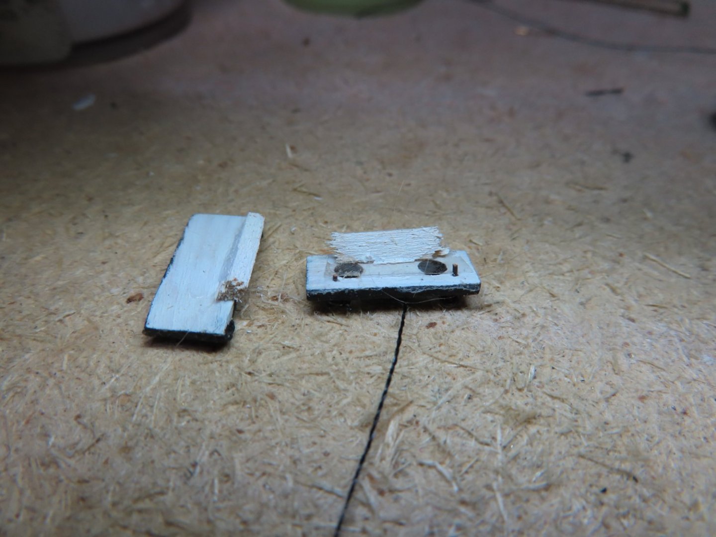
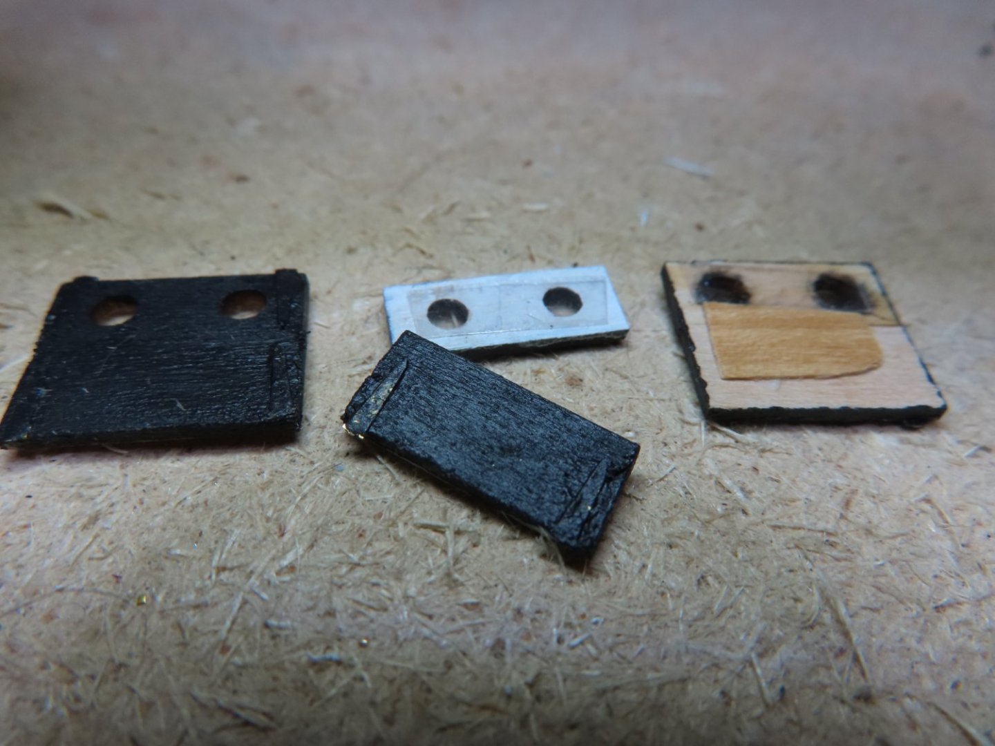
The ¼” rim circle was cut from 1/64” plywood while the 5/32” plug circle was cut from 1/32” plywood. The plug circle edges were filed to slope inward to form a short, truncated cone. The hinge was cut from 0.005” brass sheet into 1/16” wide strips. First, the rim and plugs components were wood glued together on center. Then the brass strip was CA glued to the backside almost across the full diameter of the rim piece to provide the maximum gluing surface. After the CA glue dried solid, the plugs were painted black. Slits were formed in the rail just above the hawsers with an X-acto knife for the flat brass hinge to slip into. To install the plugs, the brass strip was bent 90° so that the plug would be in the open position when inserted into the hull. The open position is needed to allow anchor ropes and chains to pass through the hawser later in the build.

-
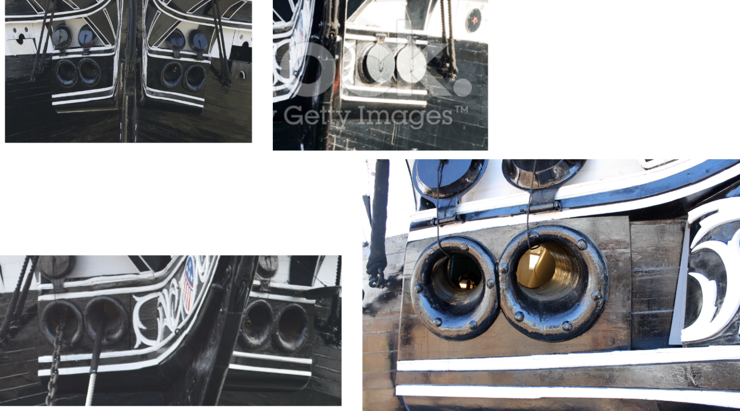
Hawser Plugs This one I almost missed, the hawser plugs, which BTW are not covered in the practicum. I thought they were going to be a little tricky; but they weren’t. Once more, I used plywood for added strength for these items due to their size. There were only three components that made up the plug: the outer rim, the inner plug, and the hinge.
-
The gun port lids were assembled and installed with the dummy guns.


-
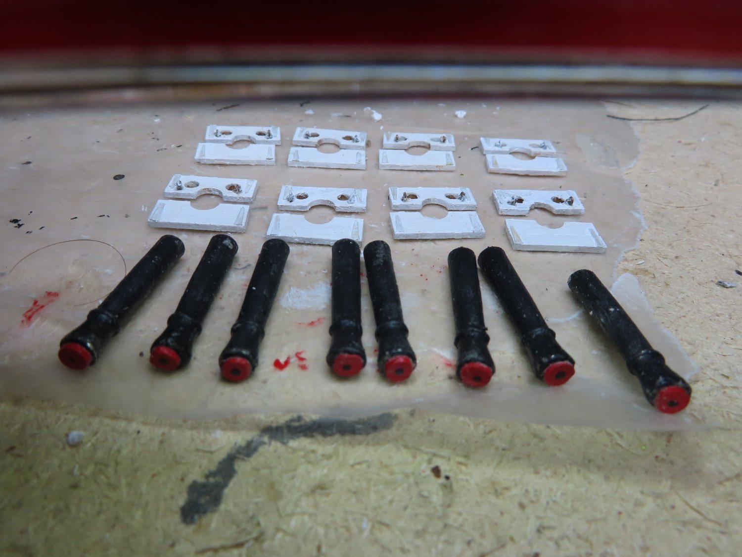
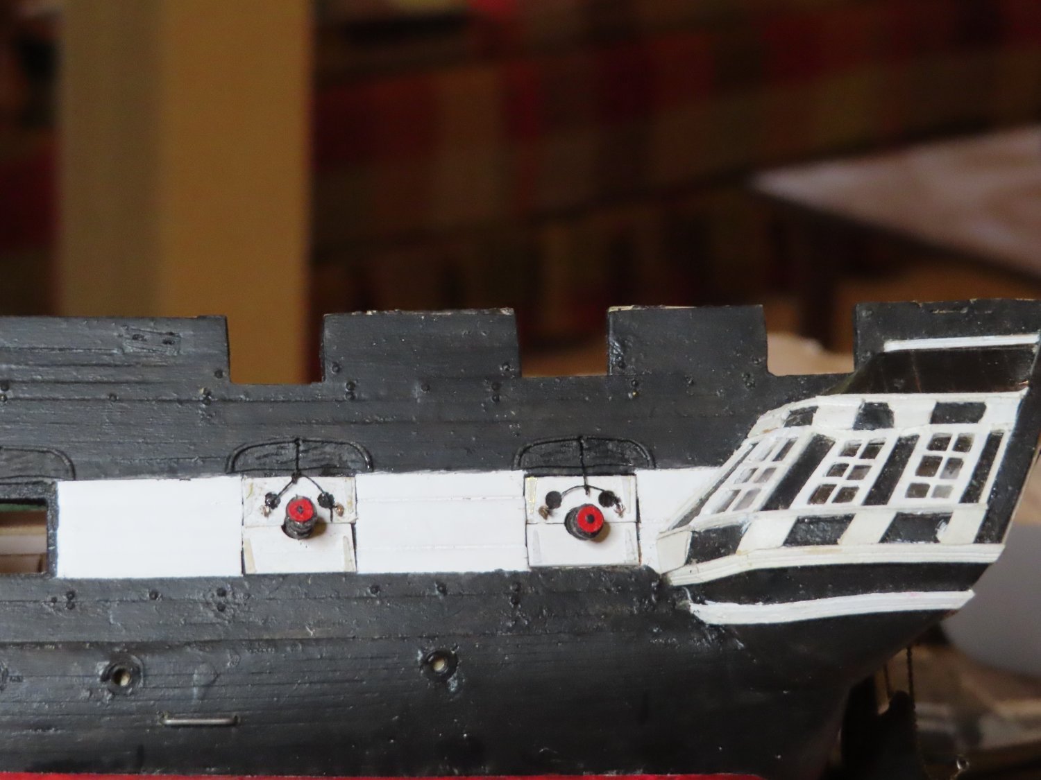
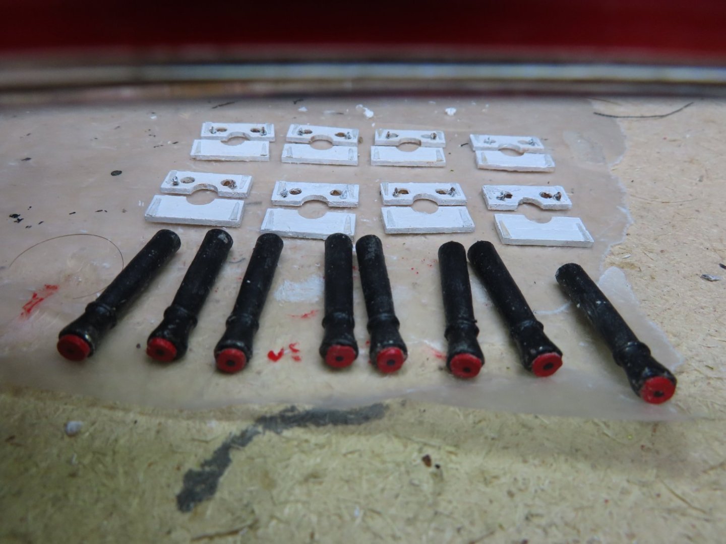
Again, the tampions were made from plywood, but this time, 1/32” thick. Looking at the photos, they look at least 2 inches thick beyond the face of the muzzle. That translates to 1/32” scale. Once again, I painted a dot in lieu of the star, this time black on red. I abandoned hanging a ring from an eye bolt in the center of the tampion as it was too small to make at scale.


-
Tampion fitted Guns The kit’s cast metal guns are OK but not great. Looking directly at the muzzles you can tell they are not perfectly round, so some detailing was required. They were painted black,

-
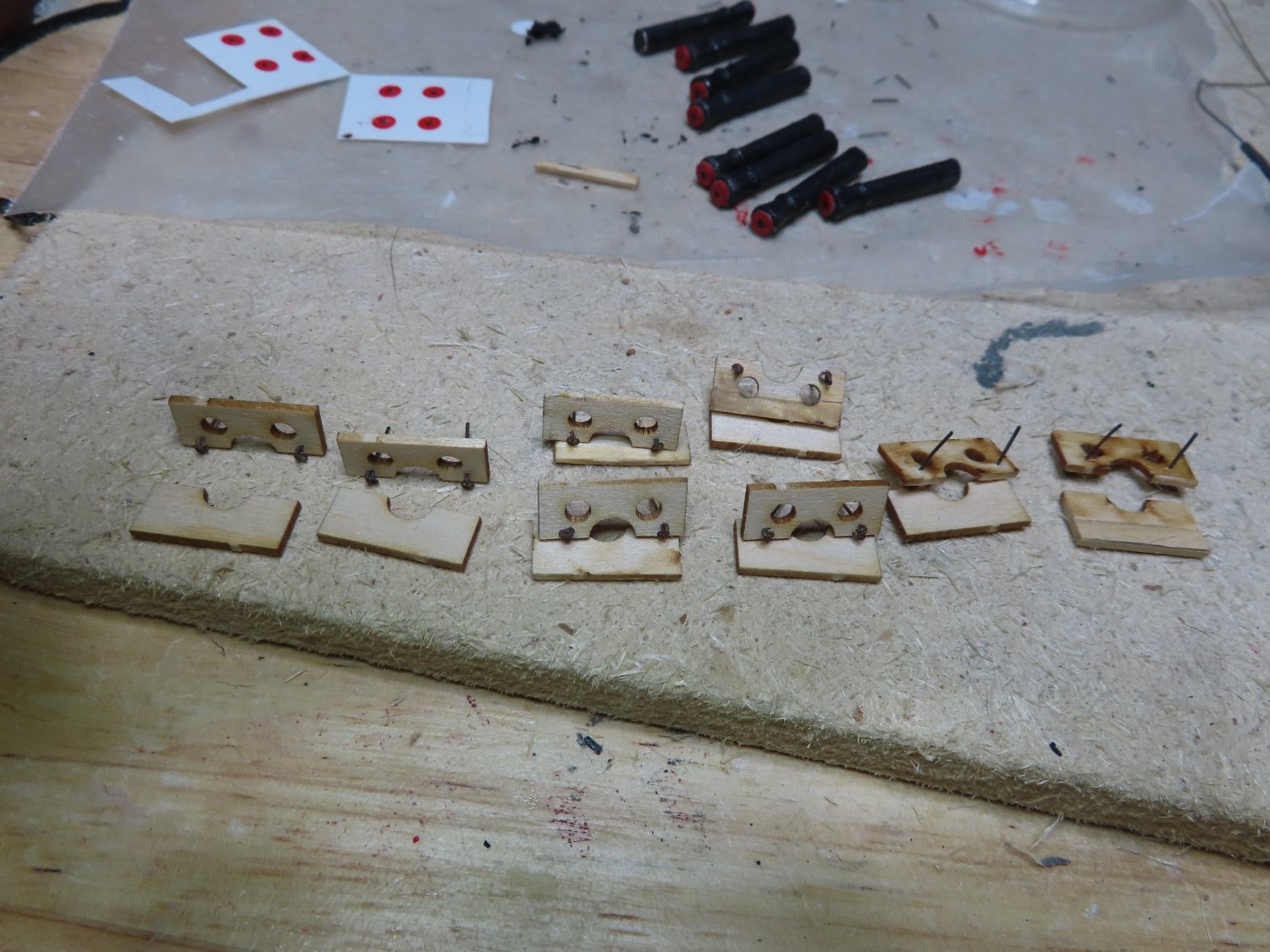
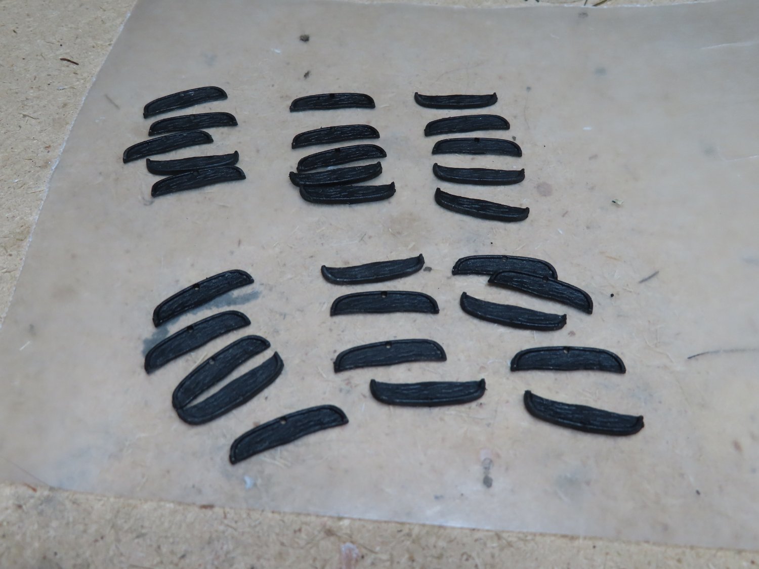
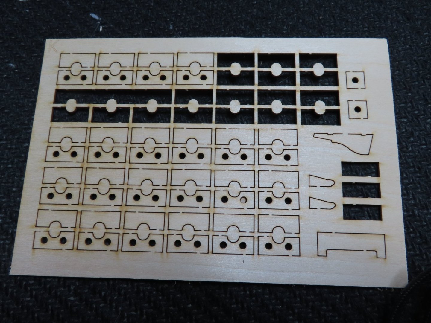
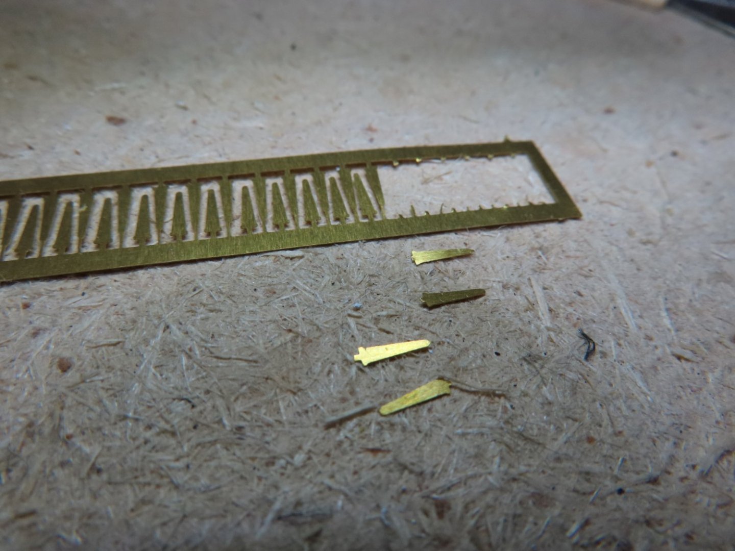
Bow Gun Port Lids Like on the transom ports, 1/32” eyebolts and scratch made 1/32” rings were used. Shown below are the parts for the bow lids. The tampions were made from 1/64” thick plywood. I tried to make a decal for the tampion so that the black star could be seen, but the resolution for this small image was quite poor and had low contrast. Instead, a red dot was painted directly on the black painted surface of the tampion which looked just fine from a foot away.
-
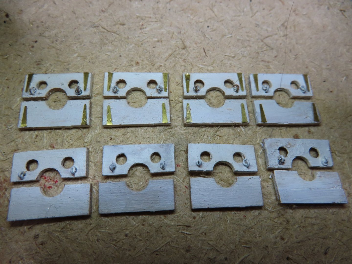
The raw gun port lids are provided by the kit which consists of an upper and lower part. The upper has two window port openings and the top half muzzle opening for the gun. The bottom lid just has the bottom half muzzle opening. The kit also provides pseudo photo-etched hinges. Mr. Hunt’s practicum creates the pull mechanism out styrene which I didn’t like. As with the port lids on the transom, the upper lid opening mechanism consisted of an eyebolt and ring assembly on either side of the lid. All the ports except the bow port will have pull lines to open the top lid. As simple as these port lids look, there are a lot of components for each one. Ten in total. 2 raw lids (upper and lower) 2 eyebolts 2 rings 4 pseudo hinges 1 thread line between the two eyebolt ring assemblies (excluding bow lid) 1 draw line thread from center of assembly line through the port gutter to inside the hull (excluding bow lid) 2 pieces of mica for the two windows openings (backside of lid) White paint
-
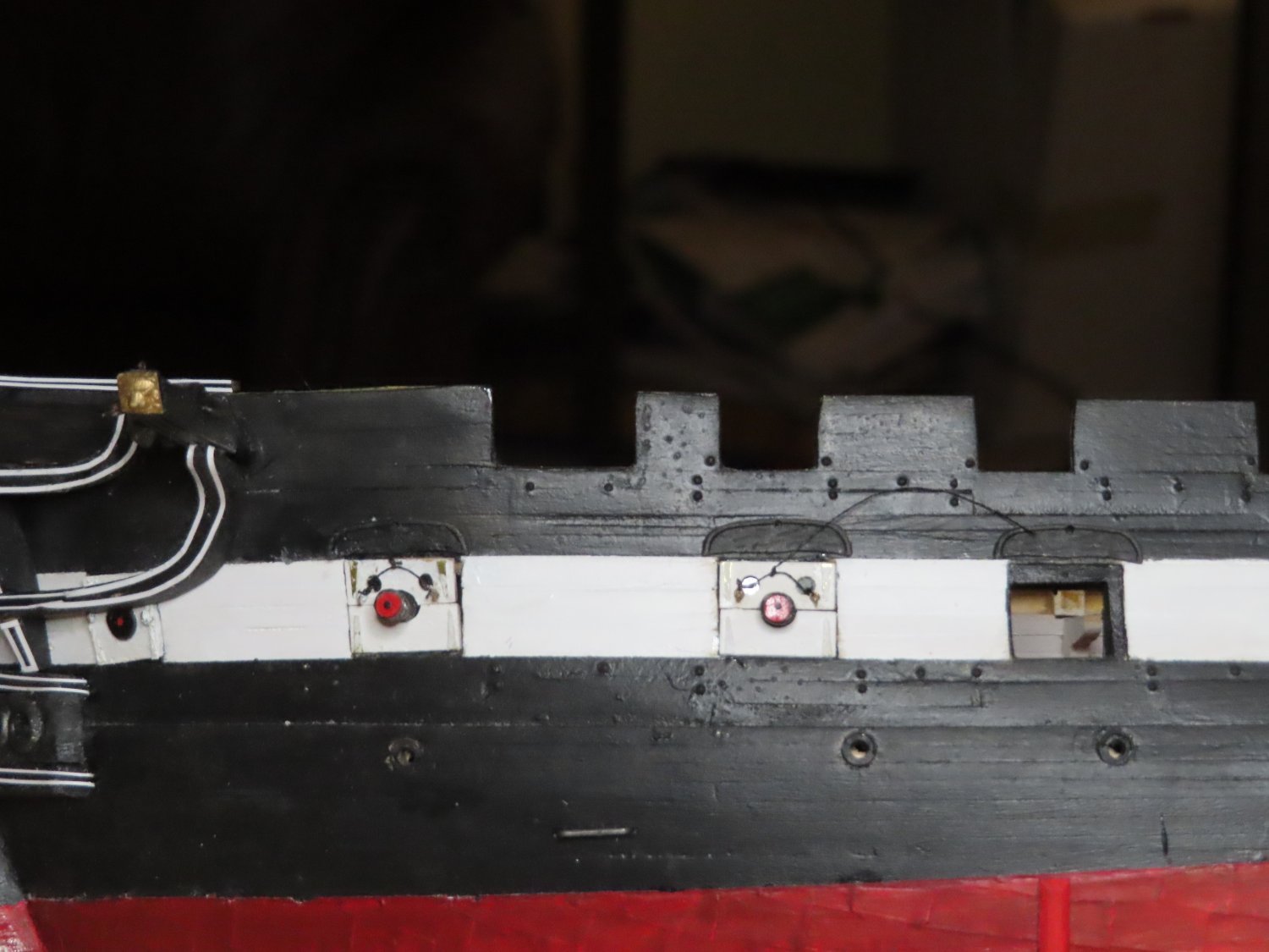
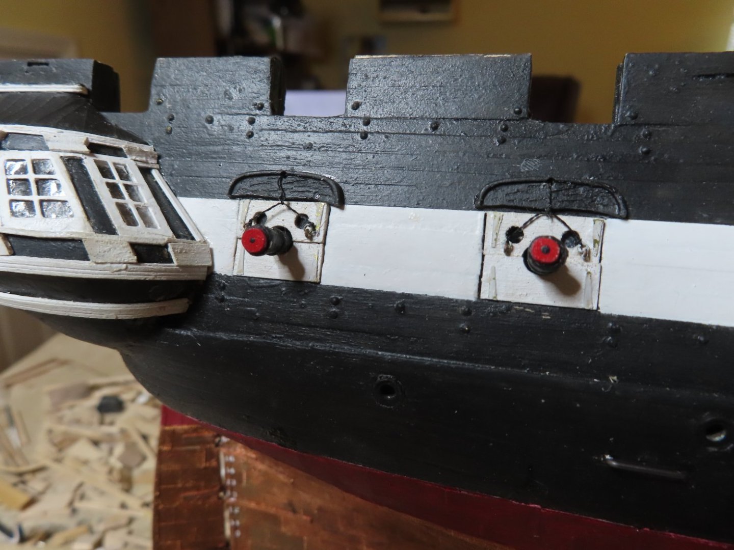
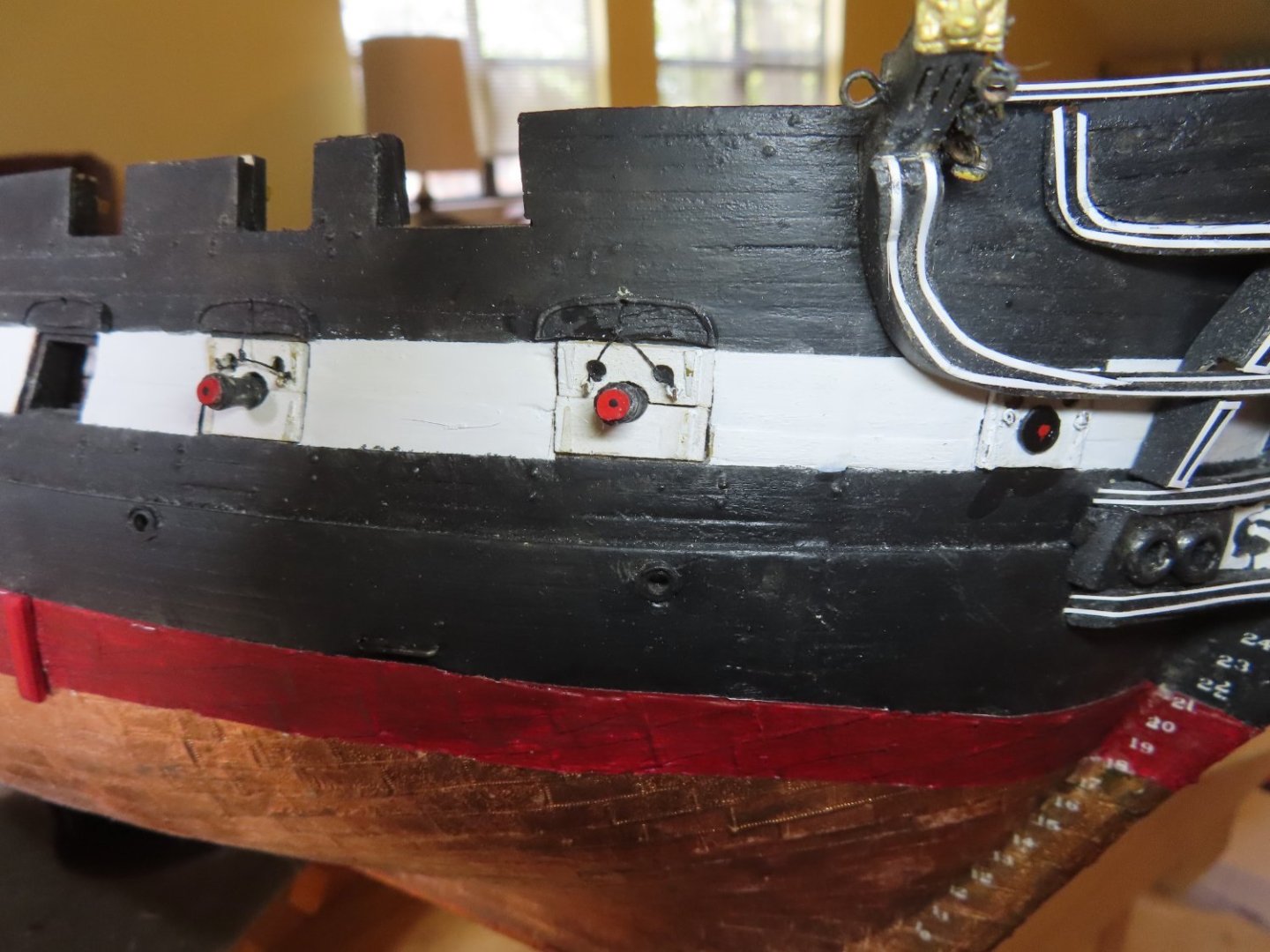
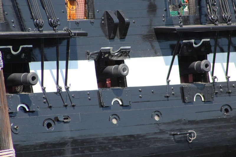
The next two guns positions moving aft on my model will also have their lids closed, but their gun muzzles will be exposed poking through the lid opening. Their tampions will be painted red with a black star. Additionally, the first two gun ports from the stern will also be presented in this manner as well. Finally, the remaining guns will be in their firing positions with their lids opened, tampions removed, extending out of the ports, and fully rigged. This will present the guns in two positions which will reduce the number of gun positions that will require full rigging. The eight guns with tampions will be dummy guns having no trucks or rigging in view. Only their tampion covered muzzles will be in view.
-
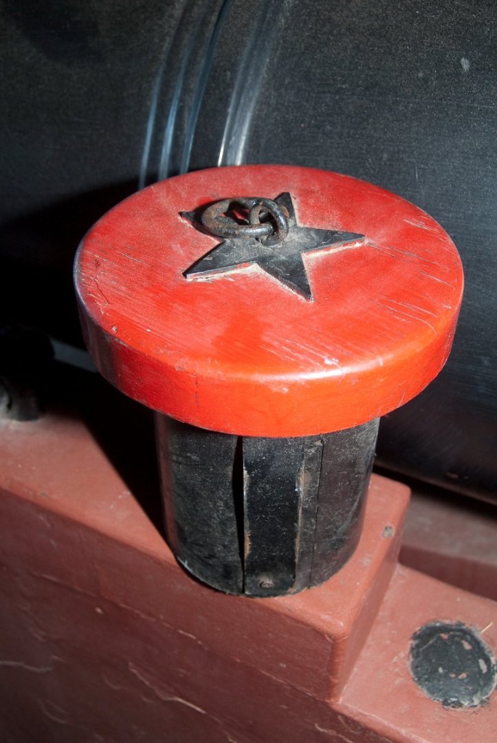
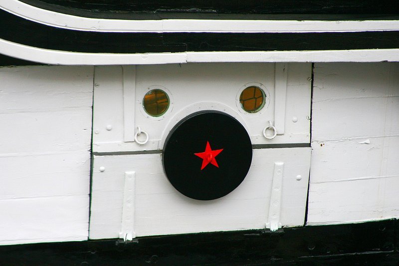
Guns with Tampions Tampions are wooden muzzle stoppers. The first gun port starting at the bow does not have a gun as there is no room for one in the interior of the bow. As a result, the lids are usually kept closed and the muzzle opening is closed with a special tampion, which is a bit larger than the a muzzle tampion. This tampion is painted black with a red star in the center.
-
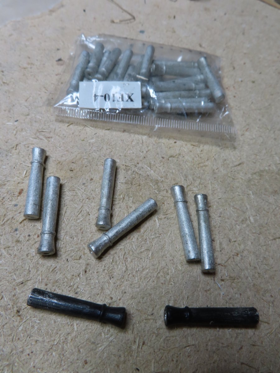
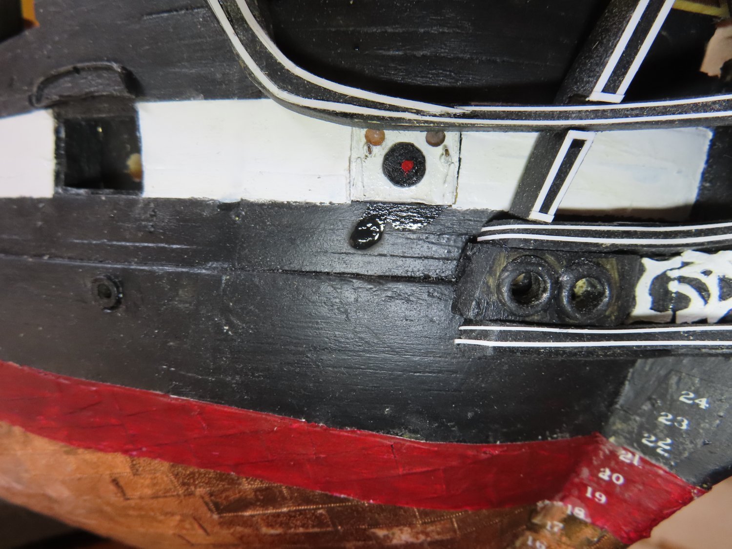
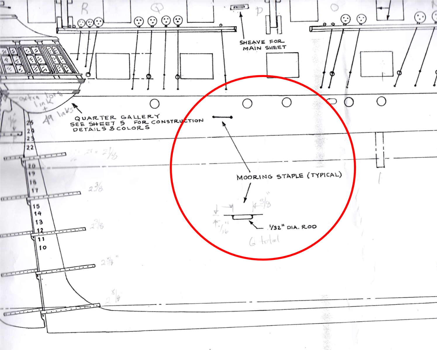
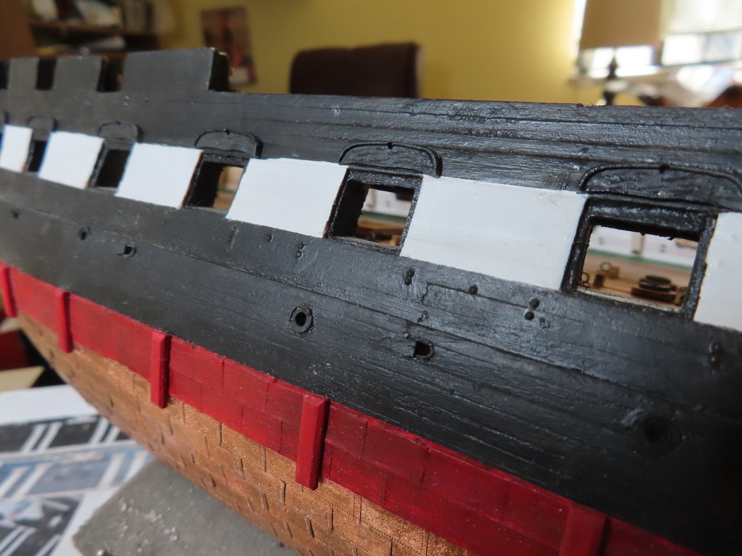
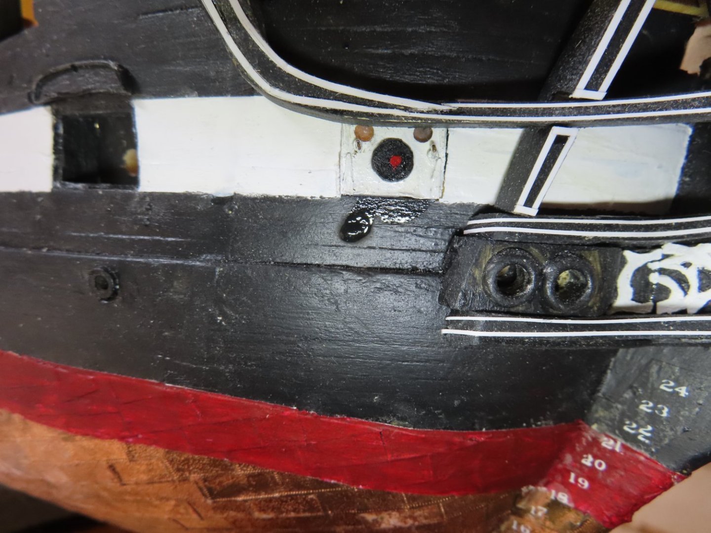
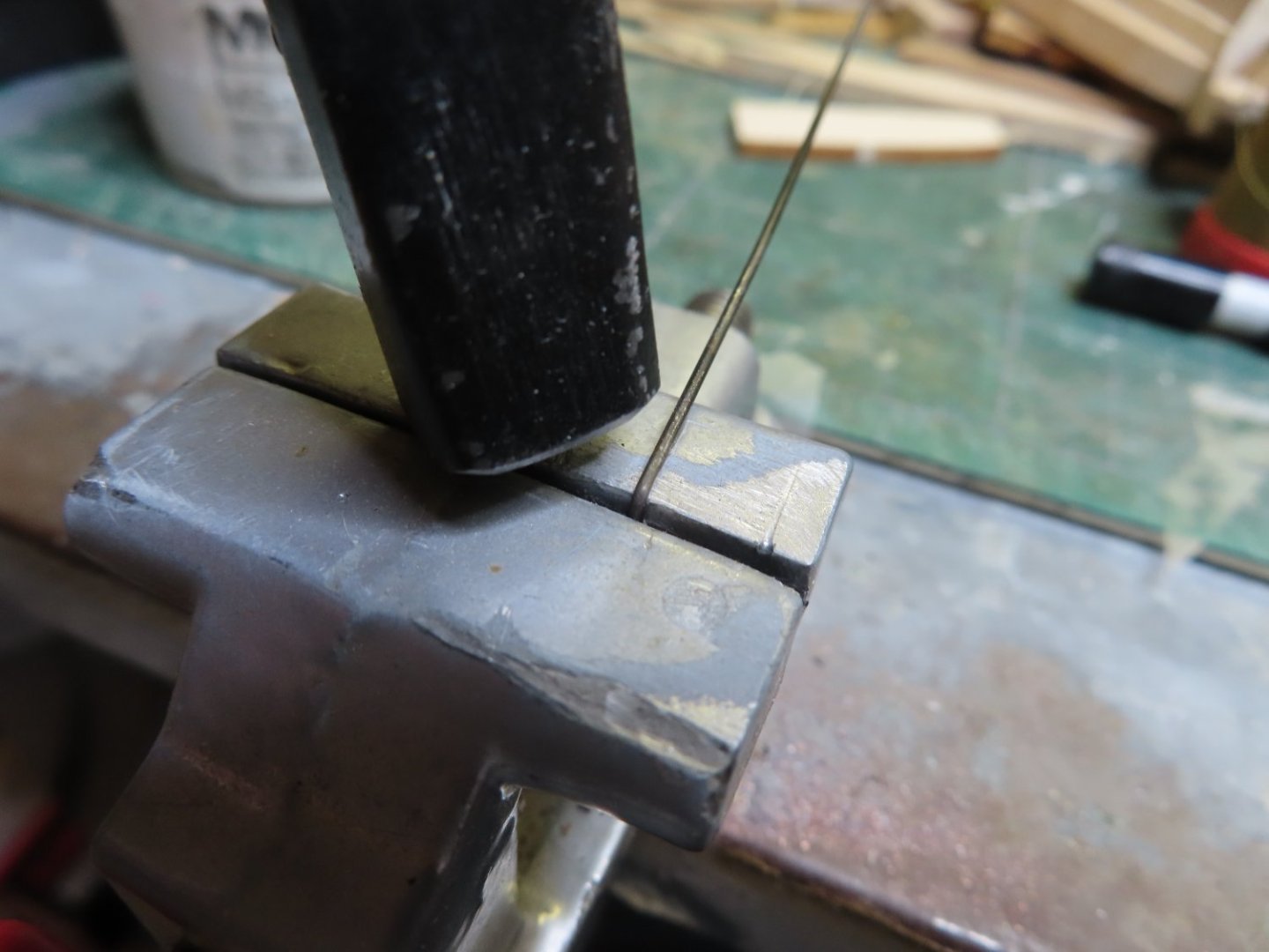
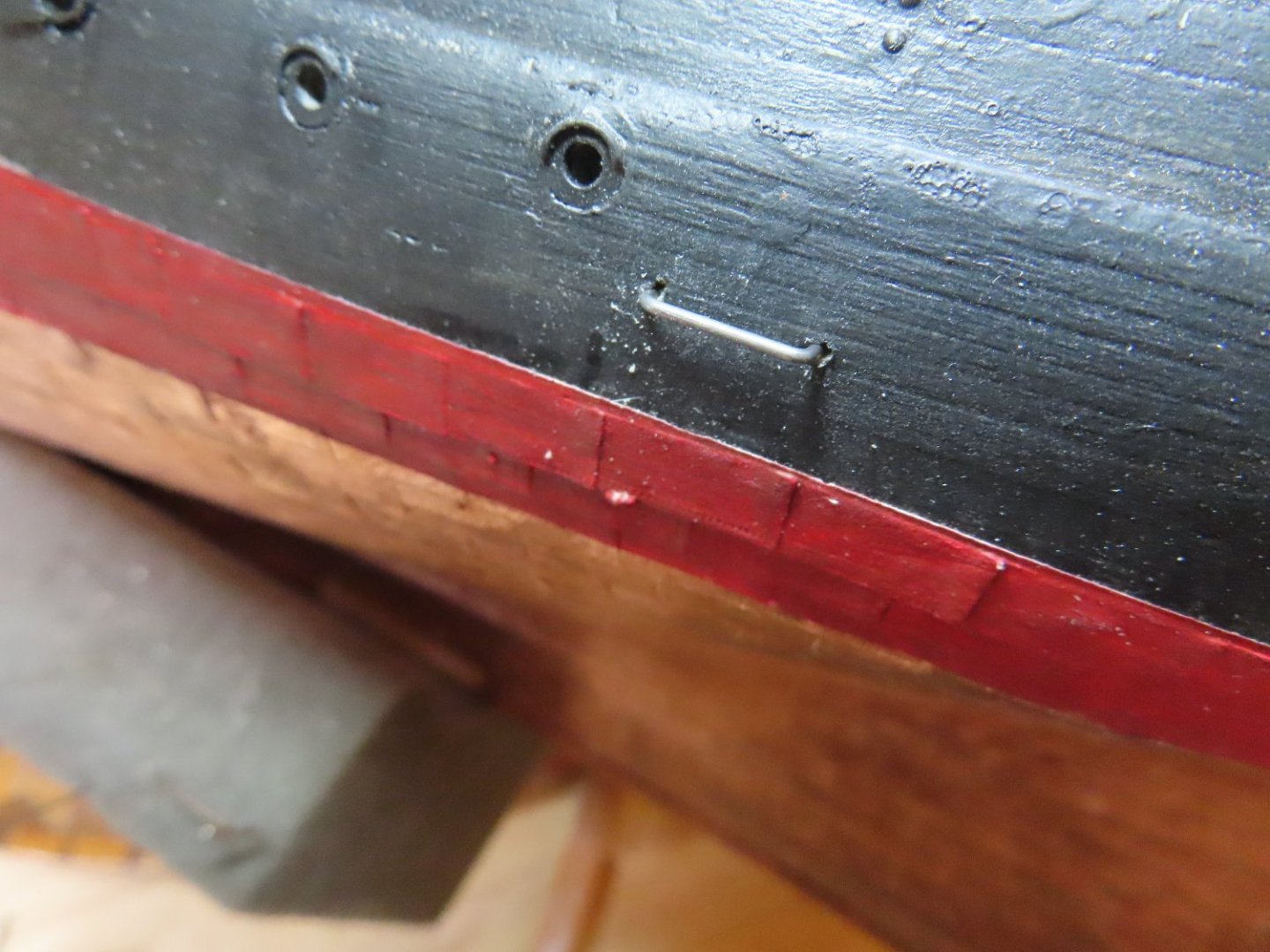
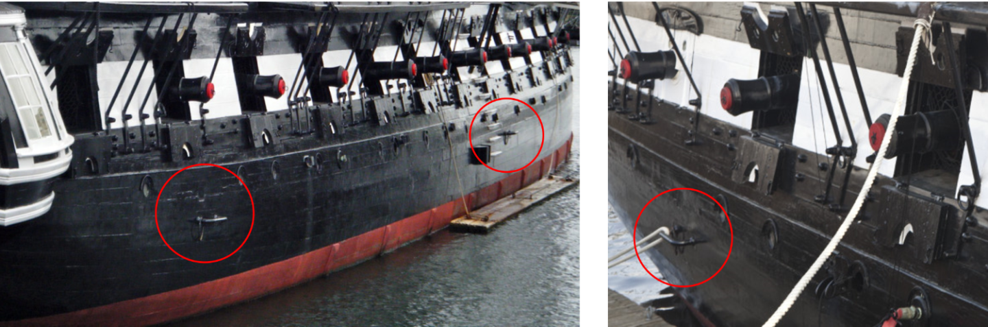
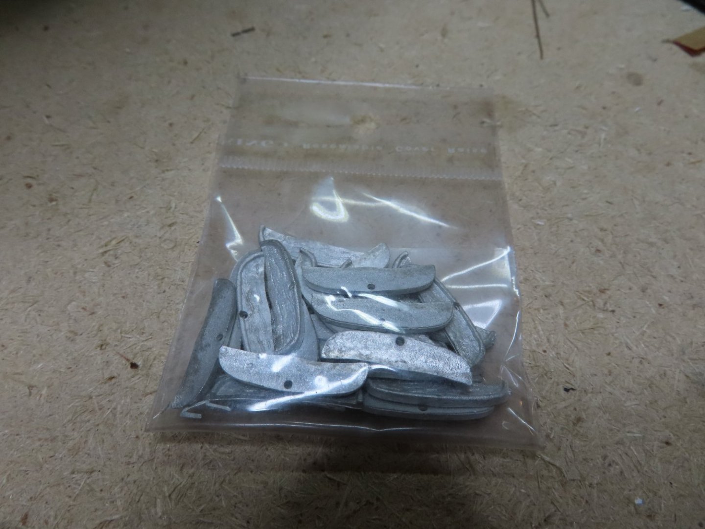
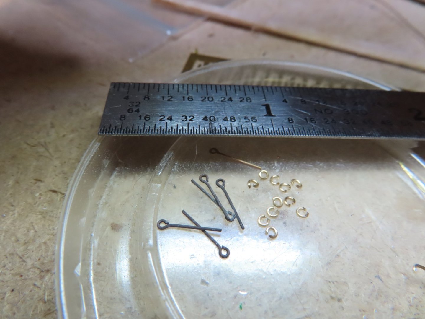
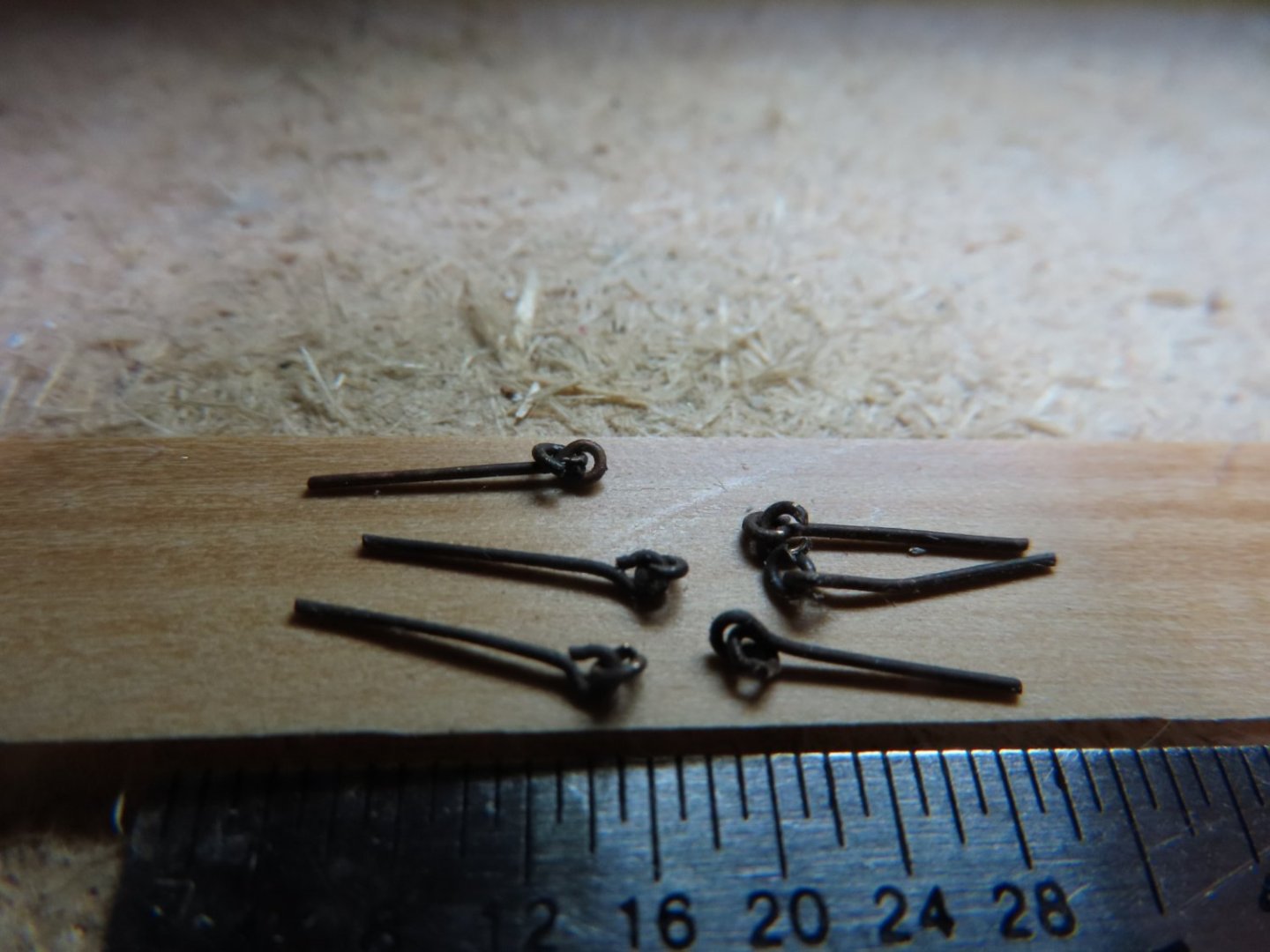
The staples were made from 0.032” music wire, close enough to the 1/32” (0.03125”) rod called out by the plans. Music wire was chosen because it won’t deform easily, and it’s dark in color. The wire was bent while in the grasp of a small vise and using a light hammer forming two 90° legs to the shape of a staple. The staples were glued into pre drilled holes in the hull.
-
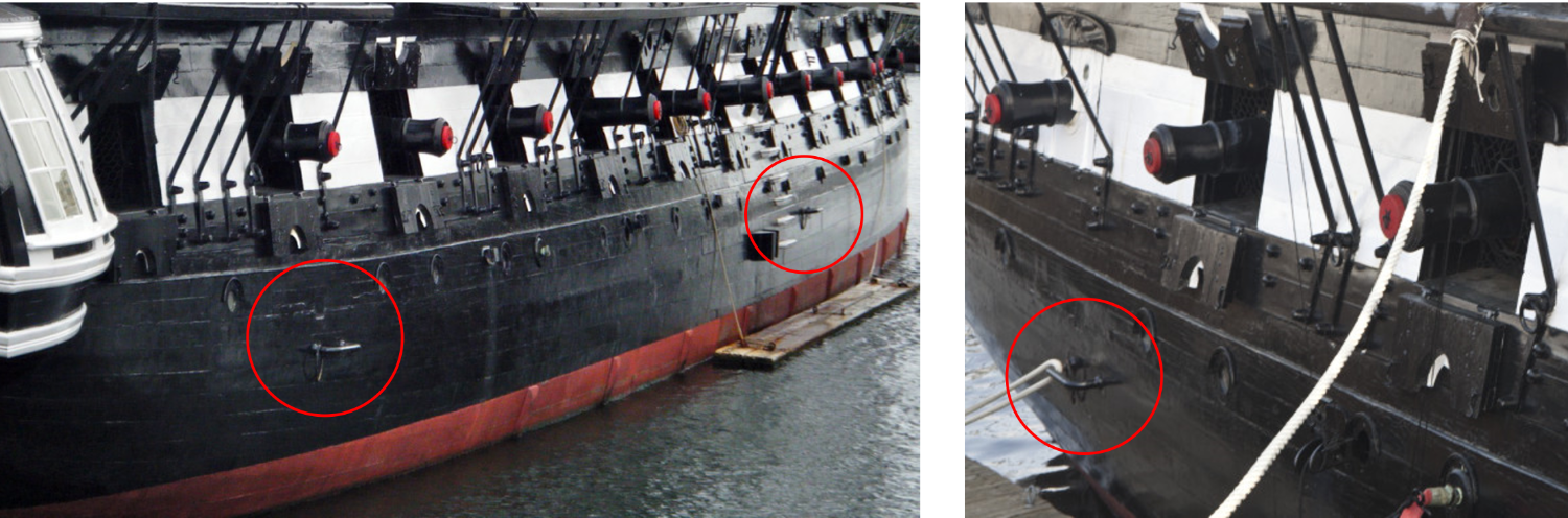
Mooring Staples Here is an item that is easy to overlook on the plans, the mooring staples. There are three of them at the waterline on each side of the hull, near the stern, amidships, and the bow. I could not find a direct image of these staples, but I was able to get glimpses of them in some photos. From what little the photos showed, there was very little detail to them other than what is shown on the MS plans.

-
Mr. Hunt's practicums were/are critical in my two wooden ship builds. My first one Rattlesnake, I followed his instructions line by line as this was my first POB wooden square rigged ship.. As the build progressed, I noticed he was taking some short cuts which I didn't care for compared to other build logs. The second build, USS Constitution, is still ongoing after 5 years. Here, based on my experience with the Rattlesnake, I am using his practicum as a guide, along with checking out any and all build logs I can lay my hands on. I had gained enough confidence building Rattlesnake to attempt a scratch built gun deck on the USS Constitution. Mr. Hunt is not perfect and even he will say there other ways of doing things, so where I have deviated from his instructions, I explain why and what I did. Jon
-
Just a minor update. In my last post, I waxed on about what the proper name was for the gun port gutters. According to Cornwall Model Boats, they are called “drip shields” and some readers in Ships of Scale site call them “wriggles.” Take your pick. BTW, since my last post, I had to take a break from the shipyard as my computer, with all my research and reference material, refused to run after 45 minutes. It would shut down like someone pulled the plug. I suspected it had to do with something related to the cooling system; mine is liquid cooled. It’s also six years old and can’t be upgraded to Windows 11. Since Microsoft won’t support Windows 10 after October 2025, I reluctantly decided to put my money into a new computer than try to fix a soon to be obsolete computer. I got the new computer from an online company I trust, and it worked as advertised. However, Windows 11 with Office 365 is a whole other animal. Because Office out of the box runs in the “cloud.” It wouldn’t read files on the hard drive or thumb drives. To use pre-existing files, you had to move them to the cloud first. I’ve got ¾ Terabyte worth of files on two hard drives I wanted to install, so that wasn’t going to happen. Long story short, I finally got the hard drives installed with help from the computer company and downloaded an offline version of Office from Microsoft. This took me away from the shipyard. But now everything is up and running save for the audio, but that’s another story.
-
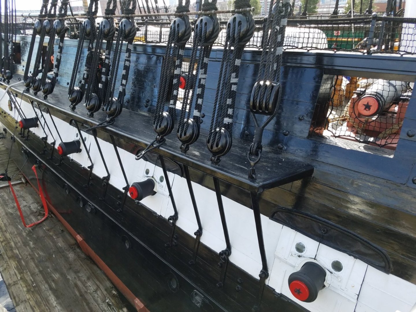
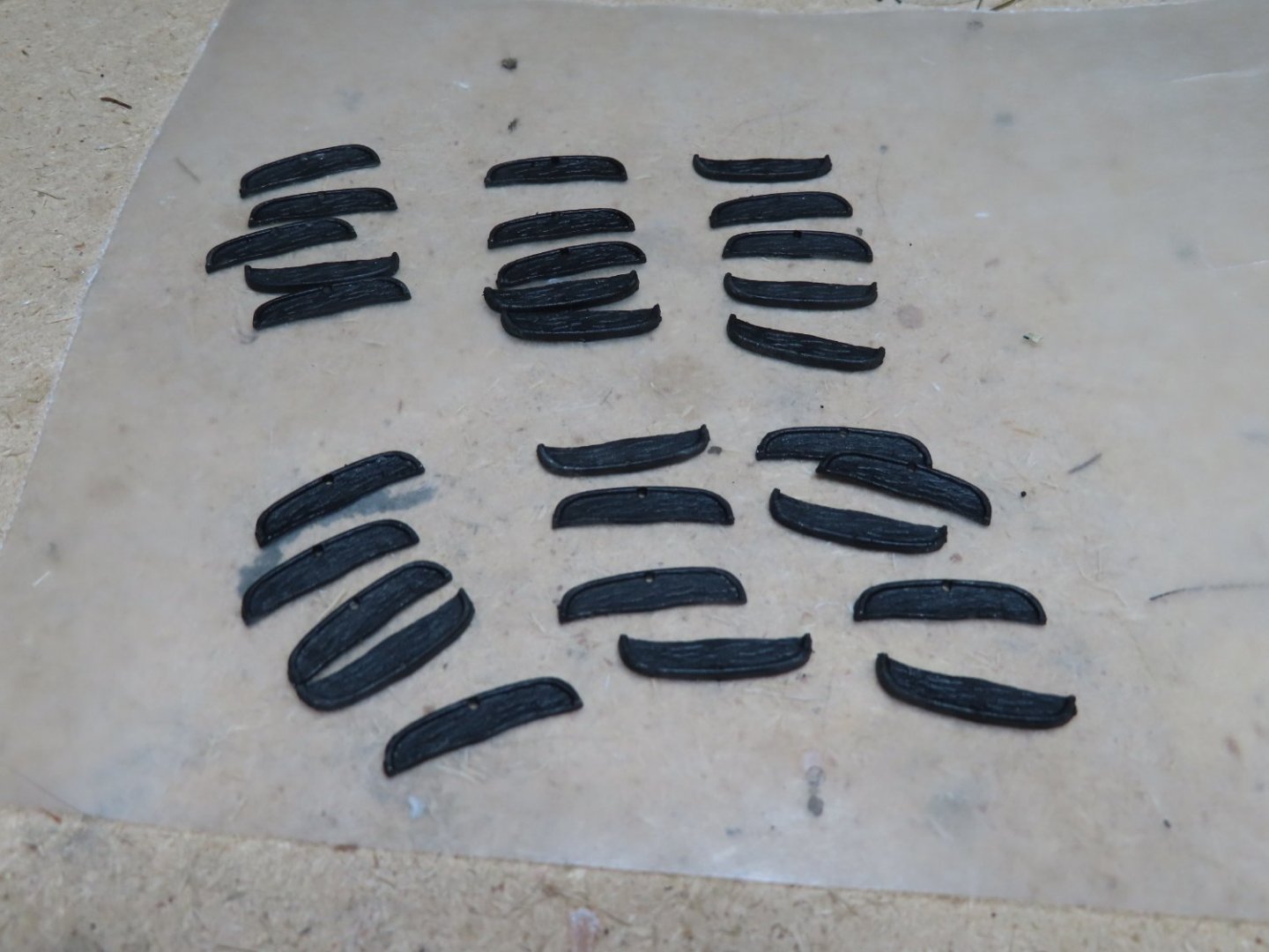
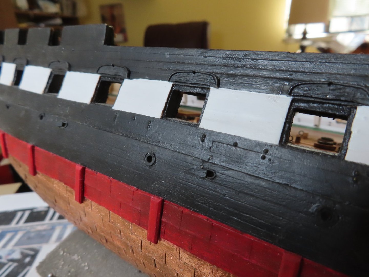
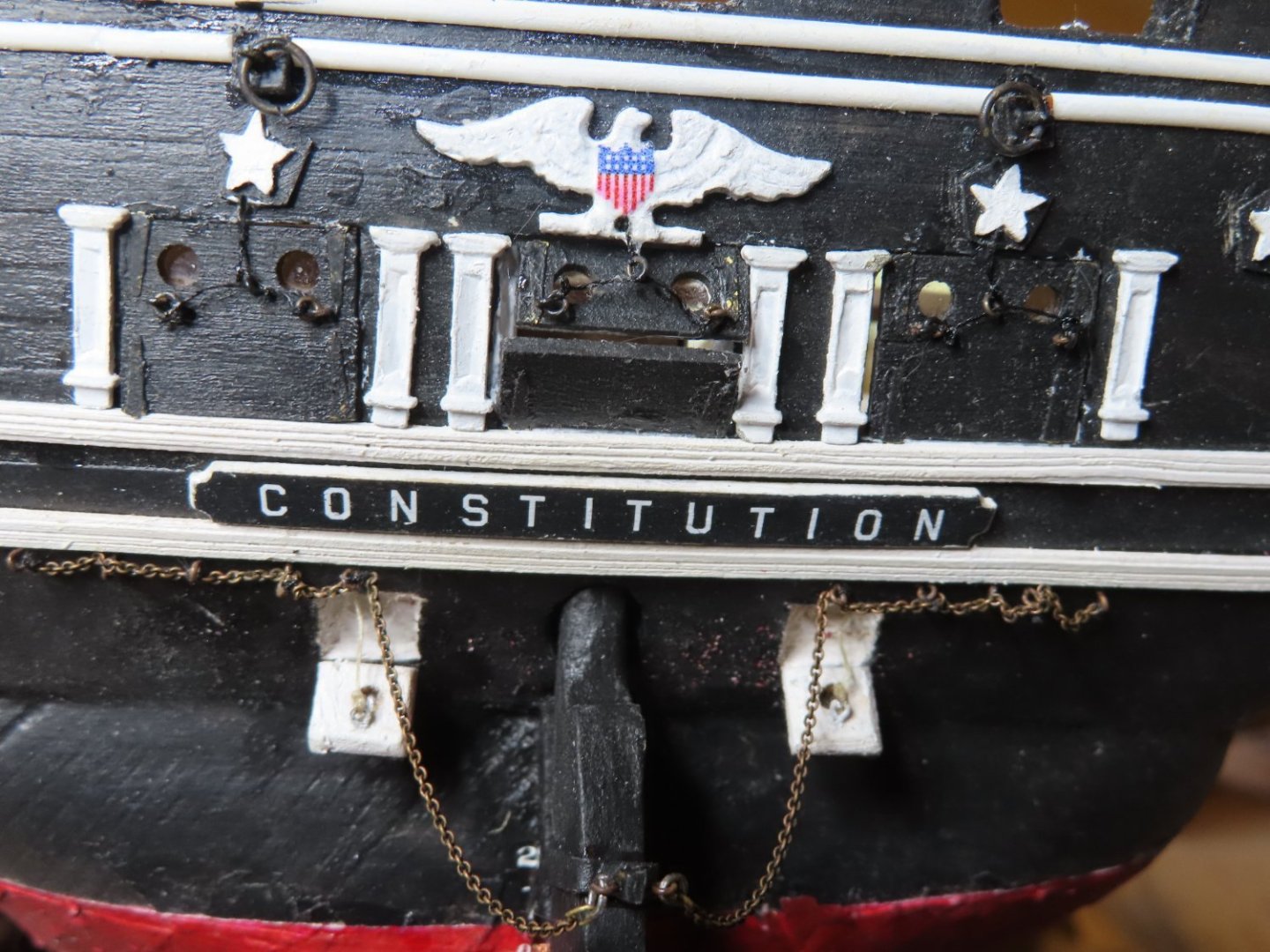
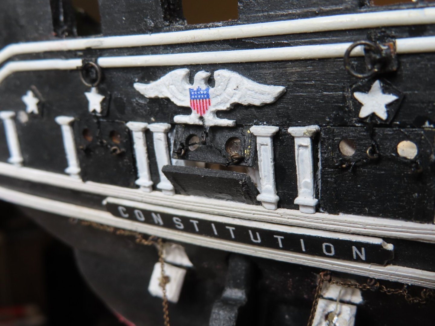
Gun Port Gutters I am not sure what the structure above the gun ports are officially called. The kit refers to them as “carved boards,” the practicum refers to them as “curtains”, and I’ve read on other build logs as being called “eyebrows.” Then there is the question, what are they made of. The kit drawing states they were a “decorative carved surface” while the practicum states were a “wrinkled canvas.” My first impression was that they were painted copper sheeting. In any case, the purpose of them was to shed water away from the guns port openings. In other words, a gutter. Luckly the kit provided these structures as nicely cast metal parts. All I had to do was paint and apply them to the hull.

-
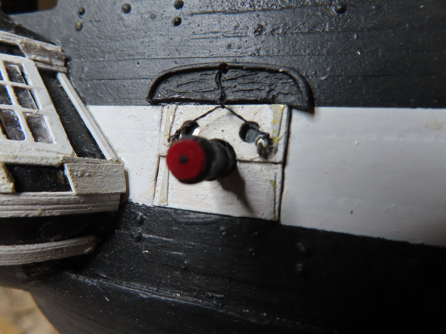
Installing the two outer doors was easy enough, just glue them in place. The center lids were to be partially open which would reduce the gluing surface, so a piece of wood was added to the edge of those half lids to establish the lid ajar angle and a gluing surface. After the lids were secured in their final positions, the loose line attached to the sliding ring was glued into position. Initially, holes were drilled into the transom to accept the pull cords, but was just easier to glue the end of the thread at the hole with no one being wiser.
-
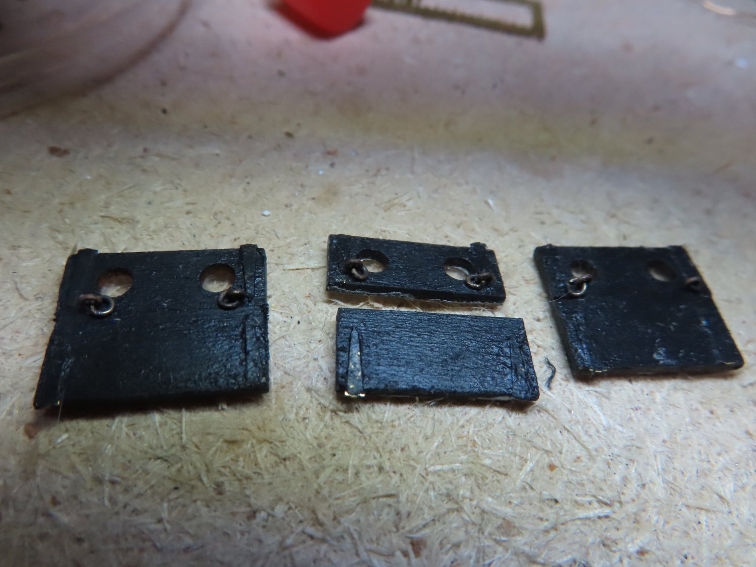
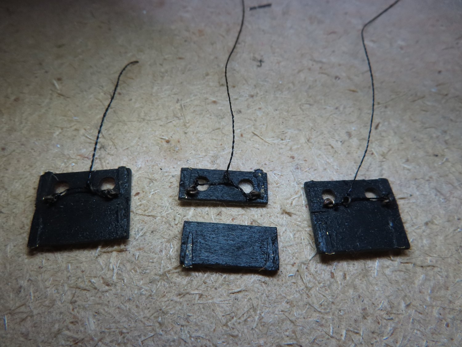
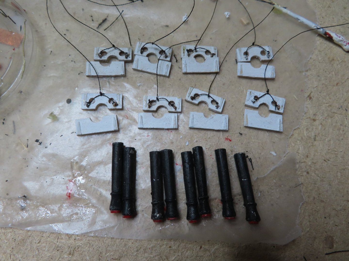
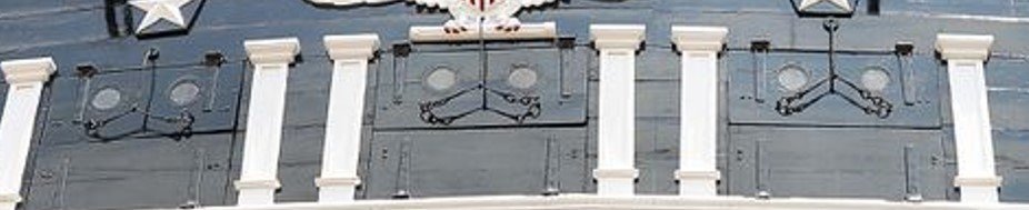
The front of the lids with the hinges attached were painted black, while the center port lids additionally had their backs painted white because they could possibly be partially visible. Then the eyebolts with their rings were inserted into the top lids. Finally, black thread was attached to the first ring in the door while the loose end was threaded through a ring tied to another thread. Finally, the loose end was tied to the remaining bolt ring on the door. As near as I could tell, the pull line was not tied to the line that went from eyebolt to eyebolt, but to a ring that could slide back and forth. This would always provide even tension to both door rings.


-
The kit does provide the 1/32” eyebolts, but I didn’t know which part of the kit they were intended for. The practicum doesn’t use them because Mr. Hunt used styrene to simulate the cord lines. I used mine that I bought as a bag of 100, years ago from Model Expo. They have come in handy many times. In addition to the eye bolts, I noticed that cord used to open the port doors is not simply tied to the eye bolts directly but have additional rings and accoutrements. Because I believe even my 1/32” eyebolts are still oversized out of scale even at this size, trying to emulate the rigging exactly was out of the question, but I wanted to suggest it. I made 1/32” rings from brass wire (the diameter of a #77 drill) in the typical way by wrapping the wire around a standard stick pin to create a length of coil, and then the coil was sliced up its length to create the rings, which were then blackened. The rings were then inserted into the eyes of the bolts.
-
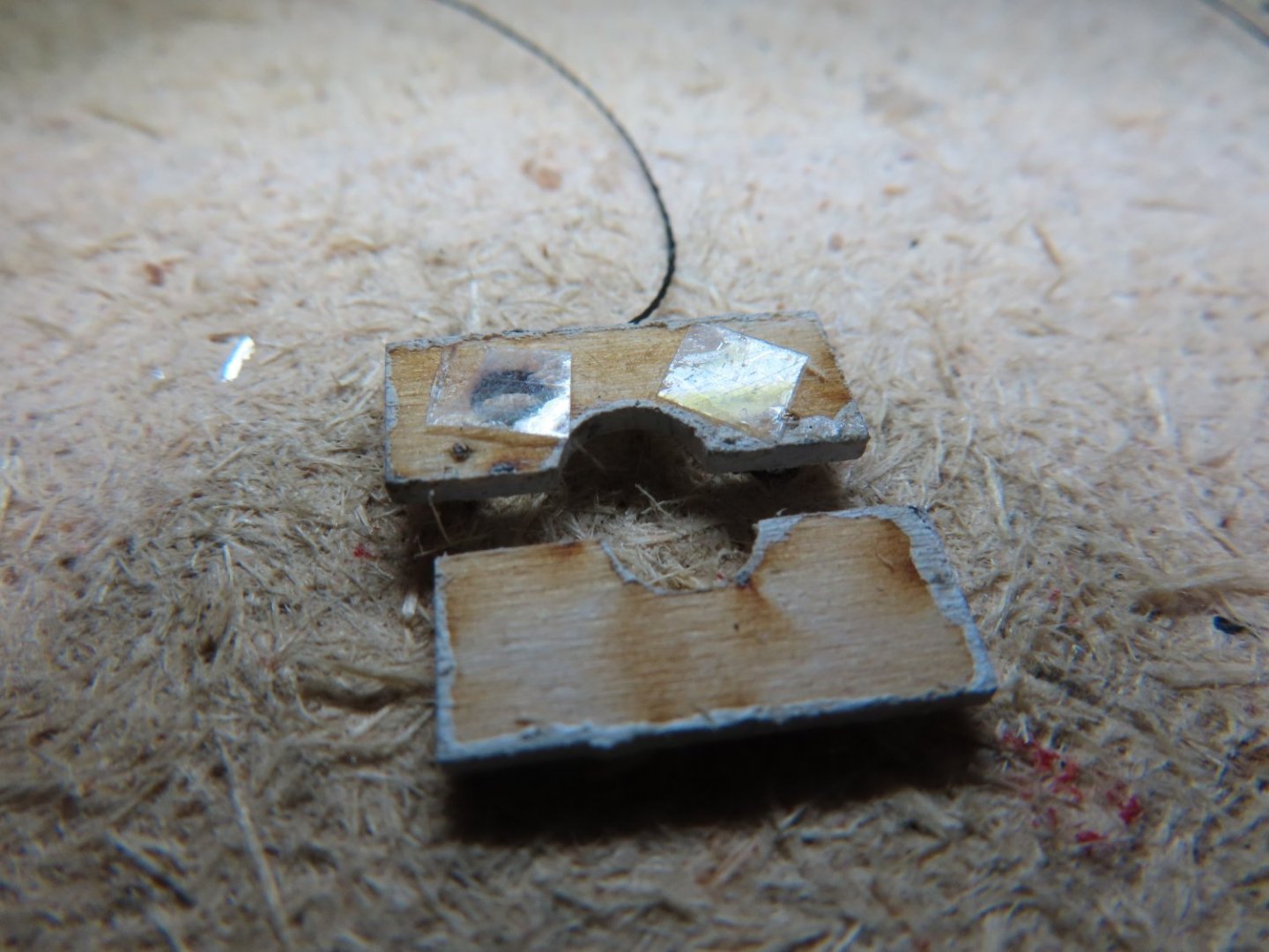
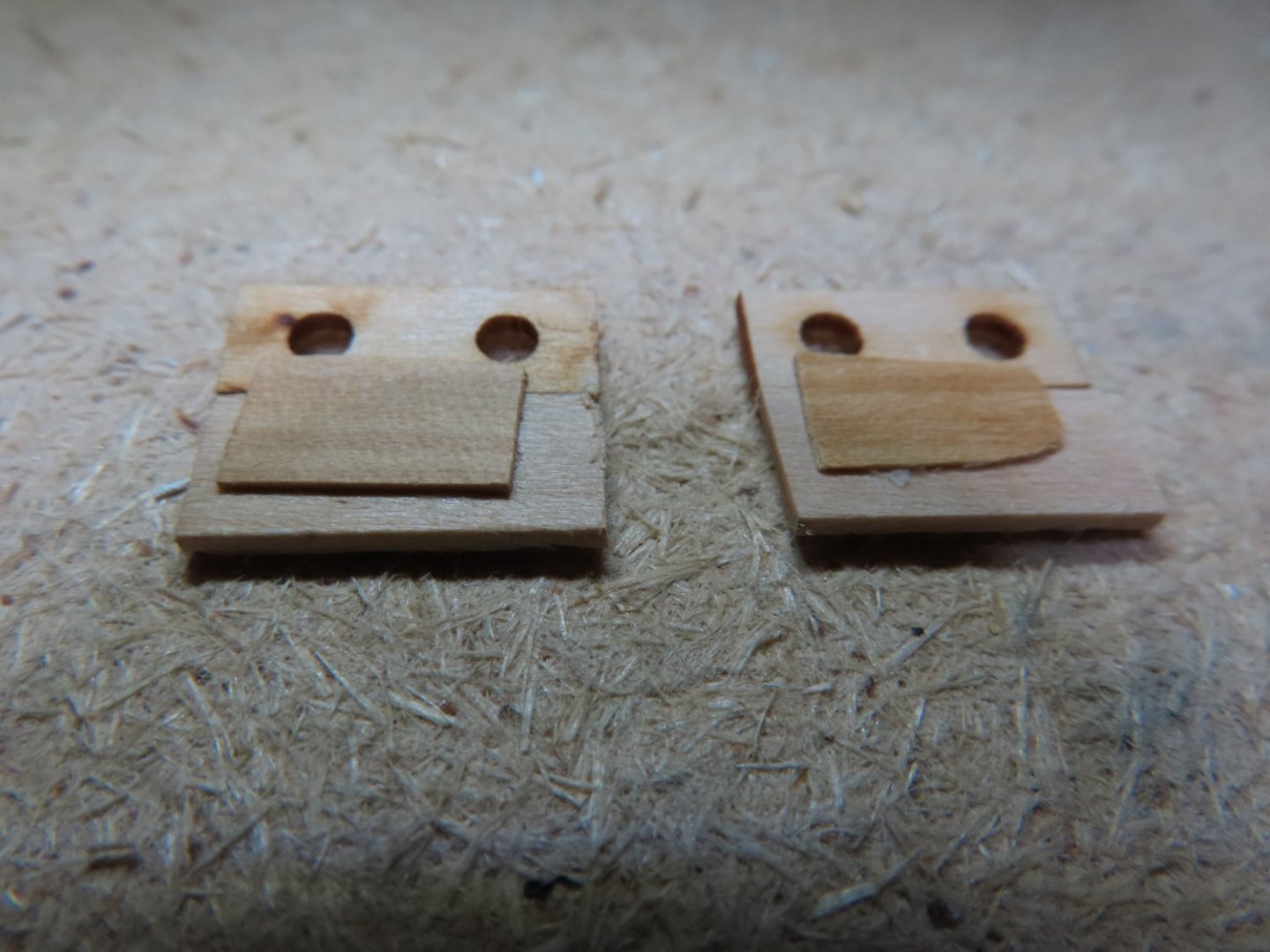
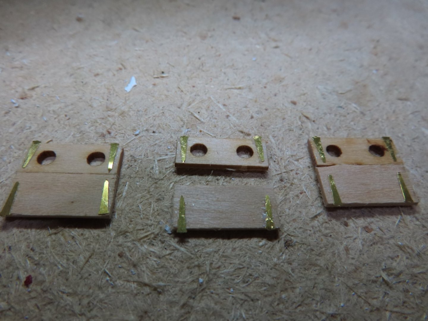
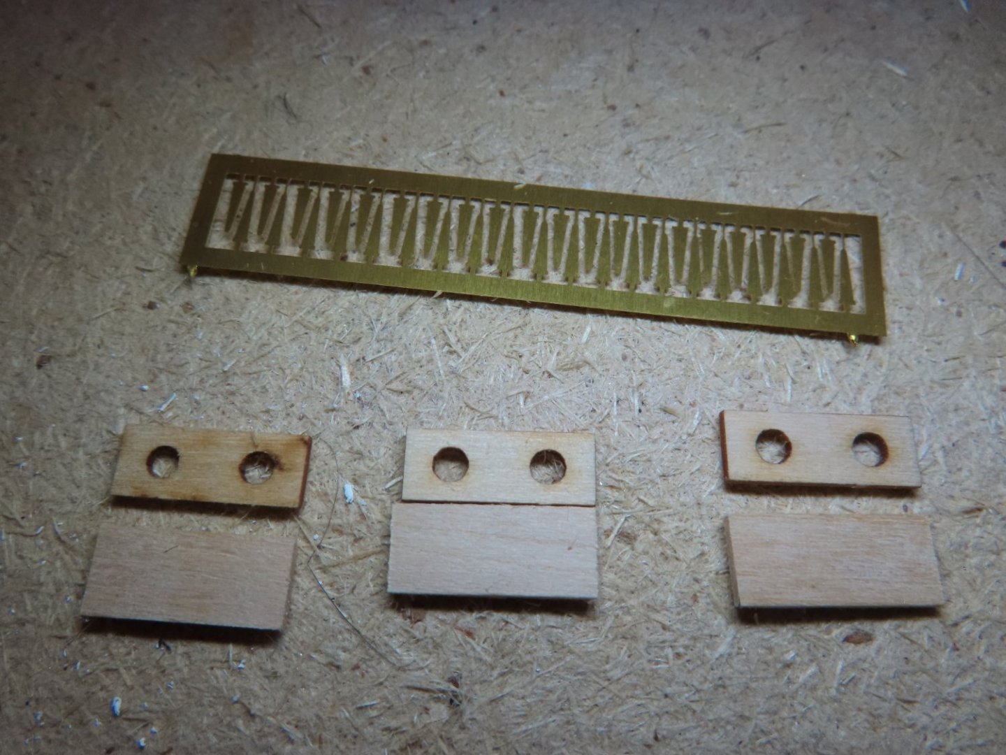
To ensure that the double lids are flush with each other, a backing was added which the top and bottom lids were glued to. Obviously, the backing won’t be seen when the port lids are installed. Then the photo etched hinges were glued on’
-
Stern Window Port Lids The last major item on the stern are the window port lids. These have changed their appearance over the years, but I am being consistent to model them as they are today, simple horizontal lid openings with no internal window sashes. The kit provides only the top half lids with the round window openings pre-cut out. The bottom lid halves are simply pieces of wood cut to size. The practicum fabricated all their lids in a closed position. I decided to open the center one partially because although there is nothing to see inside except my pseudo printed walls and flooring, I wanted the viewer to be aware that they opened. Photo-etched hinges were provided by the kit. They are just for looks and are not functional.
-
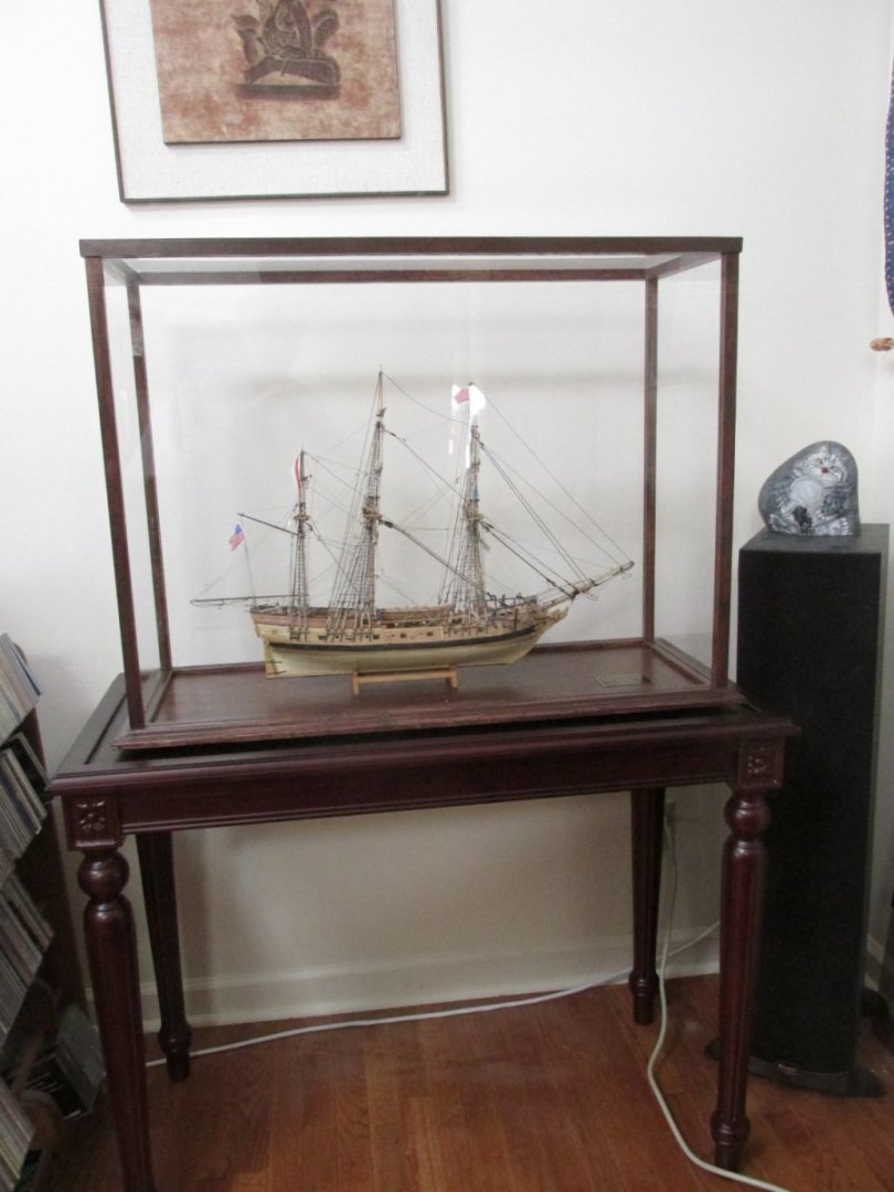
I don't remember what I paid 5 or 6 years ago for the display case, but here is the Model Expo web page I used with the current prices: https://modelexpo-online.com/Ship-Model-Displays Then I paid about as much for the table to hold the display. I also had to buy the Plexi-glass and stain the case to match the table. So all told, ballpark about $500. You can find other websites that also sell premade displays, and there are build logs which conclude their ship build with a description as to how they made their own displays. I don't have any woodworking skills or tools other than for model making so I had to buy my display.
- 88 replies
-
- 1
-

-
- Constitution
- billing boats
- (and 1 more)
-
I bought one of the cases offered by Model Expo for my 2-foot Rattlesnake. I bought the table it sits on separately from a furniture online site. I had to stain the case myself to match the table. Model Expo subcontracts out the cases to a workshop that makes the cases for them excluding the transparent material. I chose to use Plexi-glass in lieu of glass. And yes, they are not cheap. The case for my 4-foot long Constitution is going to be even more expensive.
- 88 replies
-
- 3
-
-

-
- Constitution
- billing boats
- (and 1 more)