JSGerson
-
Posts
2,646 -
Joined
-
Last visited
Content Type
Profiles
Forums
Gallery
Events
Everything posted by JSGerson
-
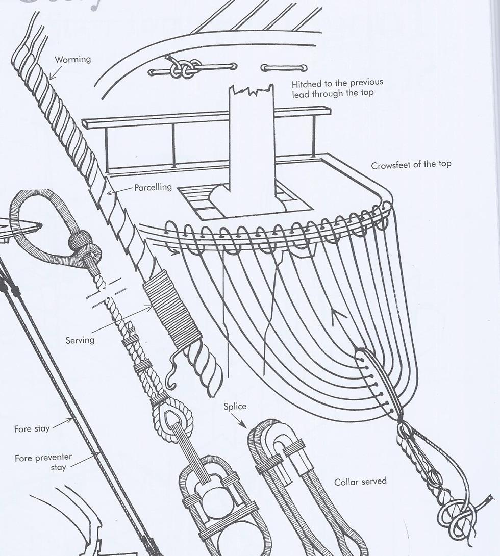
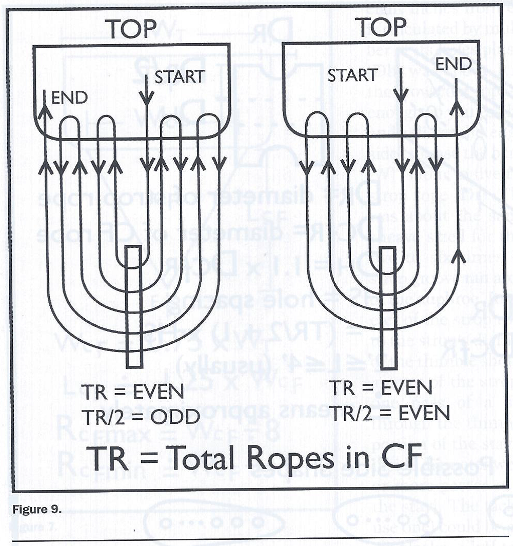
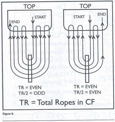
 Crowsfoot According to David Antscherl, it is now time to make the three crowsfeet. As it happens, the latest issue of the Nautical Research Guild’s Journal (Vol. 60, No. 2 Summer 2015) has an eight page article complete with photos, formulas, and diagrams by William E. Sproul entitled “Making a Crowsfoot Assembly.” How convenient…or so I thought. Up until this point I had initially followed Mr. Petersson (Rigging Period Ship Models) and then Mr. Antscherl, when I got his book. They seemed to match where their details over lapped. However Mr. Sproul appears very knowledgeable as well, but things became less certain with all the detail he provided. To determine the number of ropes that made up a crowsfoot, I counted (as best I could) the ropes in the crowsfoot as indicated on Harold Hahn’s plans and got 13. Neither the Mamoli nor the Model Shipways kit used the crowsfoot in their rigging plans. Antscherl’s book on rigging a sixth rate sloop, which is very similar to the Rattlesnake had 23 ropes. Mr. Sproul gave a formula to determine the number of ropes which he said was between 10 -24; so far so good. However he also stated that the number would have been an even number. He stated: Both Antscherl and Petersson show an odd number of lines and the crowsfoot line secured to the euphroe in direct contradiction to Mr. Sproul. Maybe it was done both ways, but since I had already drilled the holes in the tops with an odd number of holes, I will continue to follow Mr. Antscherl.
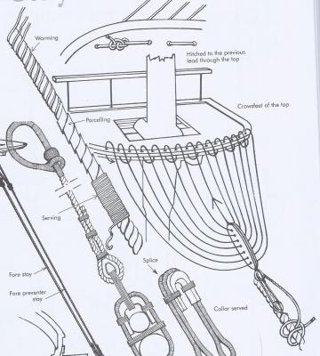
- 974 replies
-
- 3
-

-
- rattlesnake
- mamoli
- (and 1 more)
-
Fine work! I would strongly suggest that you add some pins to the stanchions so that you can anchor the assembly to the deck. I've read numerous build logs where the pin rails have been pulled off the deck when rigging lines were attached.
- 1,354 replies
-
- 4
-
-
- constitution
- model shipways
- (and 1 more)
-
Dave, I'm sure you can make the necessary fixes and most people won't know the difference. Be aware however, there may be ripple effects as a result of the repair down the line as I found out when I compensated for my mistakes. Once your fix is made you will have to check everything from that point forward for fit because now you have deviated from the plans. One of the results of my troubles with the transom was the rudder. I really didn't have much room for the rudder post. It came out of the deck a bit too close to the transom wall, so again I had to be a bit creative.
-
I feel for you. As you know, I had problems with the transom as well. Now I don’t know if this had anything to do with your problems, I documented a correction I had to make that the Practicum did not address. If you look at the image of the transom on Hahn’s plans, you are looking at a foreshortened view. A true view would be perpendicular to the face of transom. As a result, if you made your transom template directly from the Hahn plans, it was too short. I looked back over your build log and didn’t see anything where you addressed this (at least in the log). A first glance, your transom, as compared to Mr. Hunt’s appears to be installed higher. I counted the planks below your transom windows and got five, the same as Mr. Hunt’s. On my model, I ended up with four. I think if you had four planks, the transom would shift down giving more room at the top. If you made the mistake I described above and corrected it, then that would make the transom taller and also force you to increase the angle from the vertical. I don’t know if I helped or hindered you. Do what you have to otherwise you won’t feel right about the model. I’m not saying make it perfect, but make it something that you can accept and live with. Good luck Jonathan
-
Well, they built the replicate ship from something, maybe those people can point you where you need to go to get plans.
-
RevKB - Try this site for the kit: Victory Model Ships
-
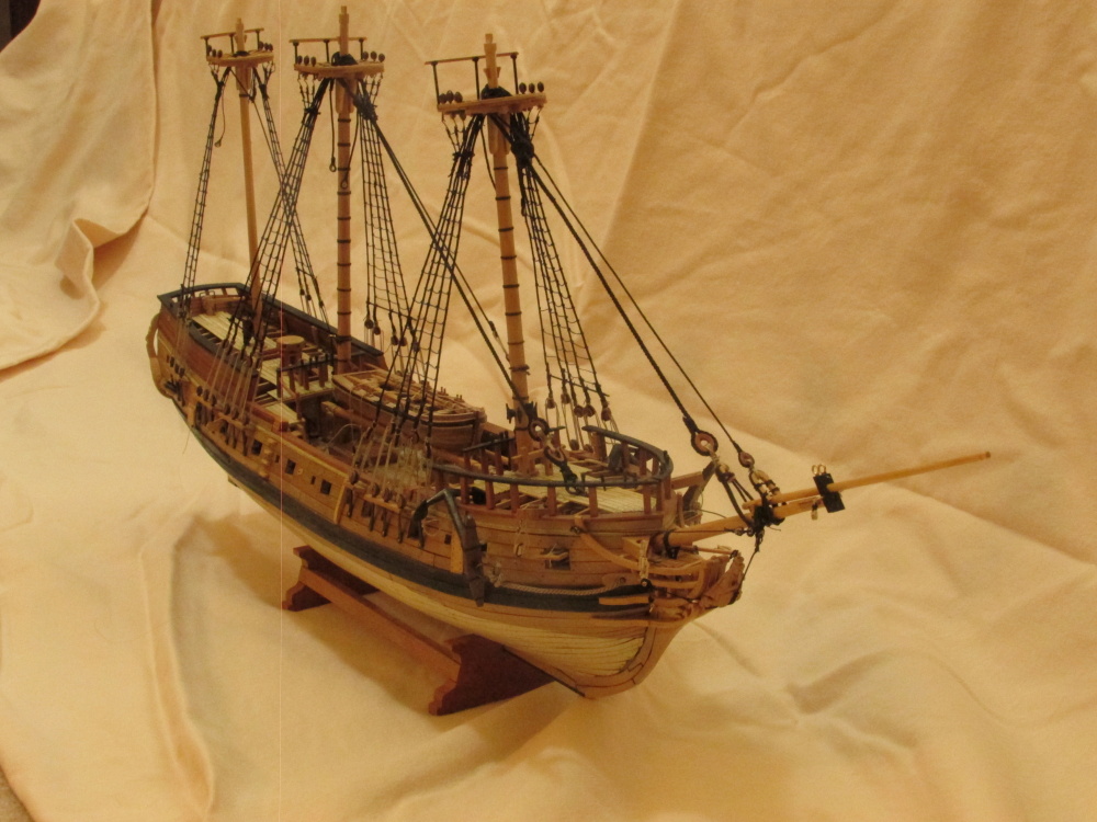
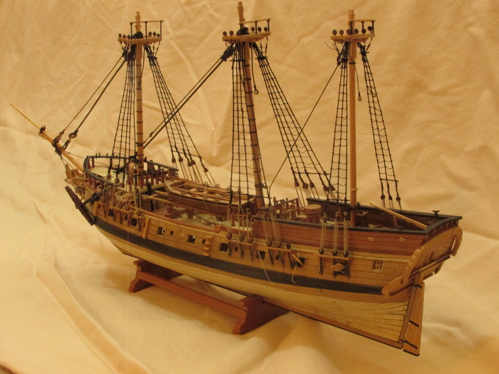
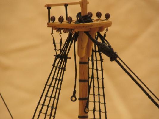
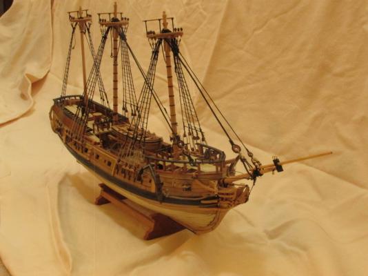
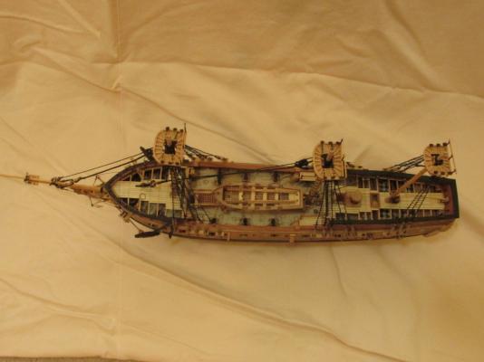
The remaining 17 futtock shrouds were made and installed. Then the shroud ratlines were installed just like before. Here is how the model looks at this stage.

- 974 replies
-
- 7
-
-
- rattlesnake
- mamoli
- (and 1 more)
-
Those were and still are my first and only carvings I've ever made. I just took it one small step at a time. All I can say is try it, you have nothing to lose (except wood and time) and who knows, you may be a unknown Michelangelo!
-
Even with your perceived errors, they appear very minor if at all detectable, in the images. Your planking looks like it well on its way to a handsome hull.
- 481 replies
-
- 1
-
-
- rattlesnake
- model shipways
- (and 1 more)
-
Thanks for the feed back. I always learn something from you.
- 515 replies
-
- 3
-
-
- artesania latina
- whaleboat
- (and 1 more)
-
How was the final height achieved? How did you trim the excess wood on something so fragile? Did you just file or sand paper it?
- 515 replies
-
- 2
-
-
- artesania latina
- whaleboat
- (and 1 more)
-
You had the same results as me on those moldings. Your triple molding doesn't look too bad from what I can see except the grooves aren't as pronounced as the double - same as I got. Those wooden molded surfaces are very delicate and will dent real easy. I immediately used a couple coats of poly-wipe to saturate the wood to protect them.
-
If the coals are hot in the oven, and there is a pot on the stove, then there has got to be something in the pot! Soup? Mush? Pot Roast?
- 572 replies
-
- 5
-
-
- constitution
- frigate
- (and 1 more)
-
I don't remember if I had the interference problem with the oar sweeps you described. but your solution would have been the same as I would have done (did?). Here is something else to consider at this point - the hull sheaves. Bob Hunt 's practicum discusses these much later (Chapter 9.7) as a simple add-on and look rather crude. I didn't even know they existed or what they were at this point in my build. However if I had known, this would have been the time to construct them or at least plan for them. Bob's method was to just drill a single hole in a small thin rectangular piece of wood and through the completed hull. This is actually a block built into the hull. It has a wide opening, a pulley wheel inside,.and is flush to the hull. Once I realized what they were, I tried to make mine at least look like they were built in. They are probably numerous ways to construct these, but one method is to drill two holes in a rectangular block whose thickness is a little bit thicker than the completed hull. The openings (both sides) are then carved to simulate a block. It is installed in the proper position in the hull frame. Once the planking is completed around it (inside and out) the excess wood is sanded down flush to the hull surface. Jon
-
Your hull sheaves look a lot more realistic than mine since mine were added after the hull planking was done. I assume you drilled holes in a piece of wood, did some carving, and inserted the piece through the hull with some support pieces. What are the problems you discovered with the stern?
- 481 replies
-
- 1
-
-
- rattlesnake
- model shipways
- (and 1 more)
-
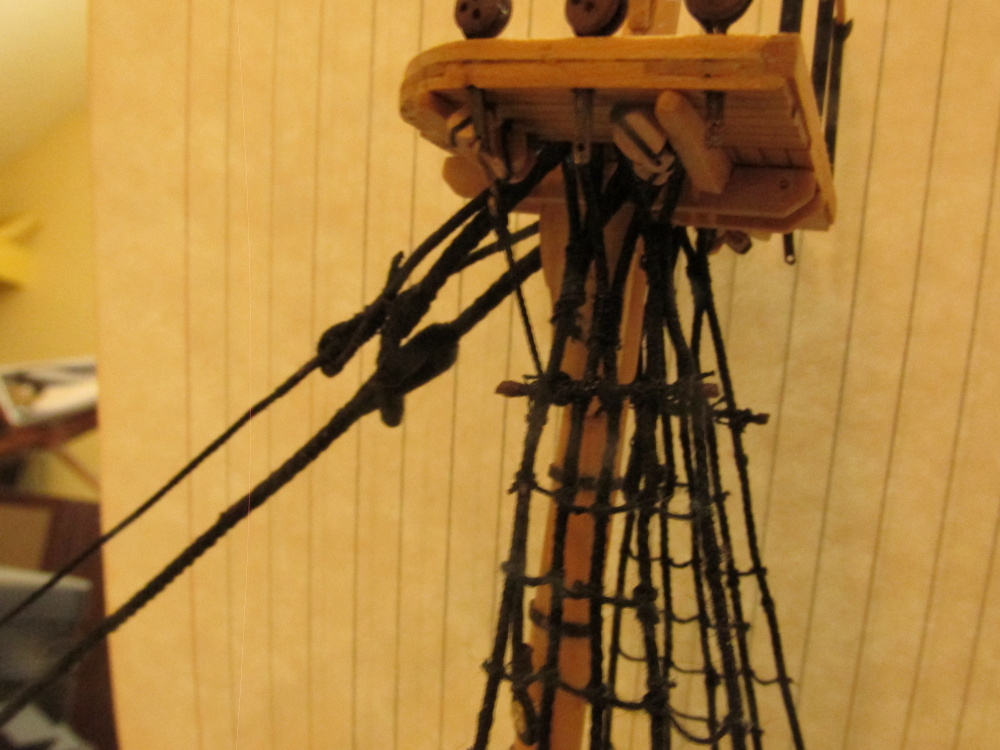
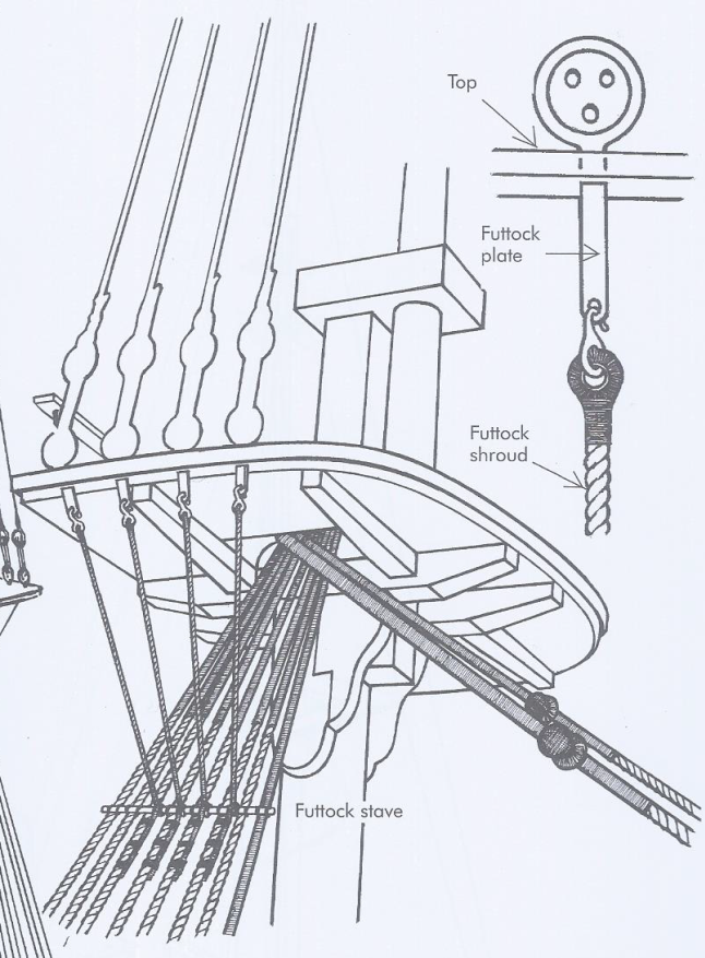
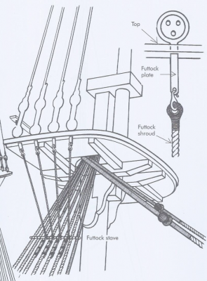
Finally, the futtock plate is bent to the required angle and the futtock shroud is hooked on. The other end of the futtock shroud is wrapped around the stave and lashed to the shroud. The diagram shows three lashings but I used two. One down, 17 to go.

- 974 replies
-
- 5
-
-
- rattlesnake
- mamoli
- (and 1 more)
-
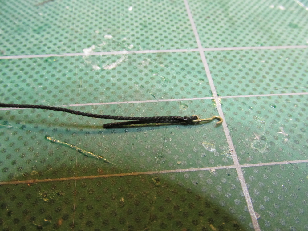
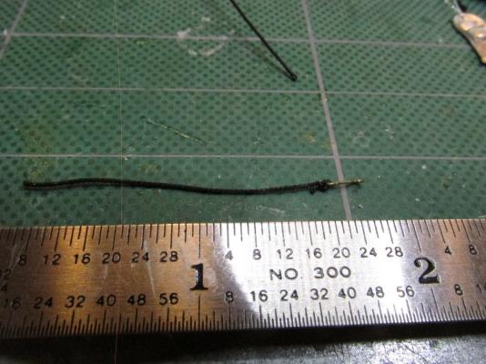
According to the references, the end of the futtock shroud was seized around the thimble. Since I wasn’t using a thimble I decided I would also forgo the seizing due to the scale. The seizing would have made making a small loop almost impossible Instead I used a technique I had seen described in various build log to make a pseudo eye splice and thus get the tiny splice I wanted. Basically one takes the end of the thread/rope and passes it through itself once to create the loop and a second time to create the pseudo splice and added strength. A tiny dab of glue holds it all together and then the excess thread/rope is trimmed.

- 974 replies
-
- 2
-
-
- rattlesnake
- mamoli
- (and 1 more)
-
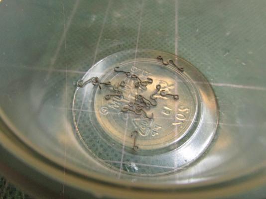
Next the hooks 18 in total, were blacken and were ready for use.
- 974 replies
-
- 1
-
-
- rattlesnake
- mamoli
- (and 1 more)
-
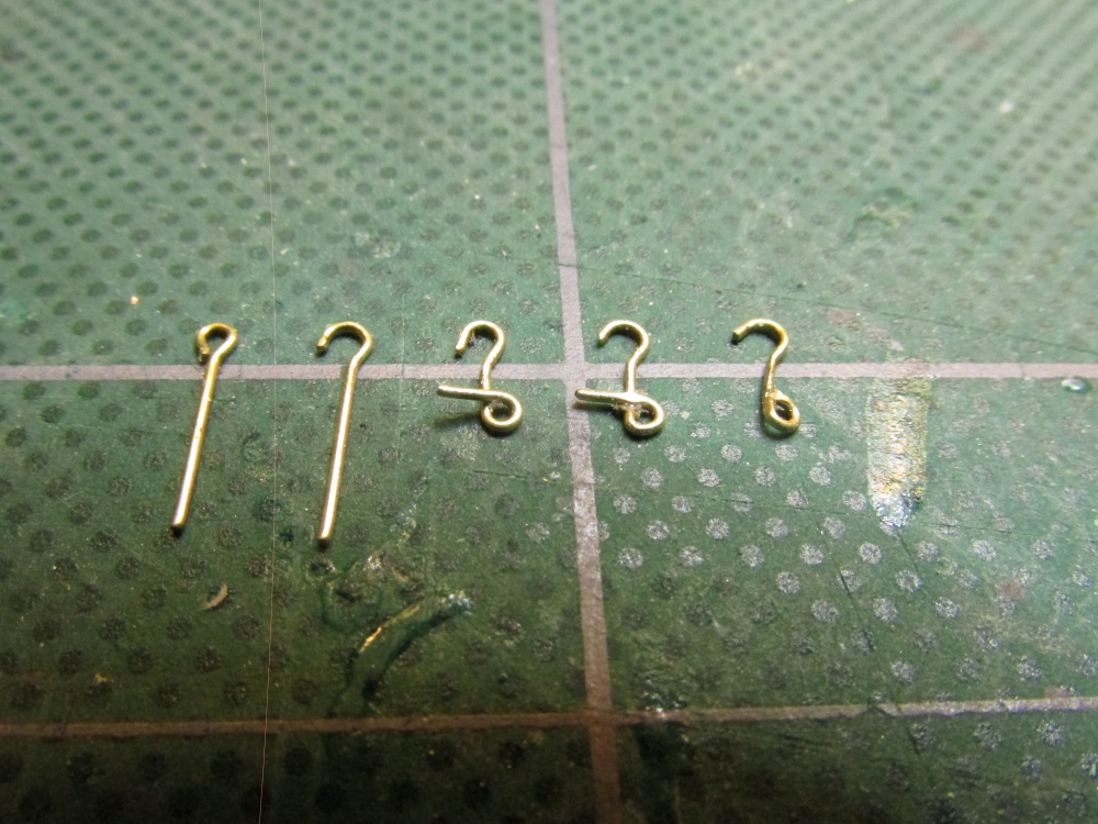
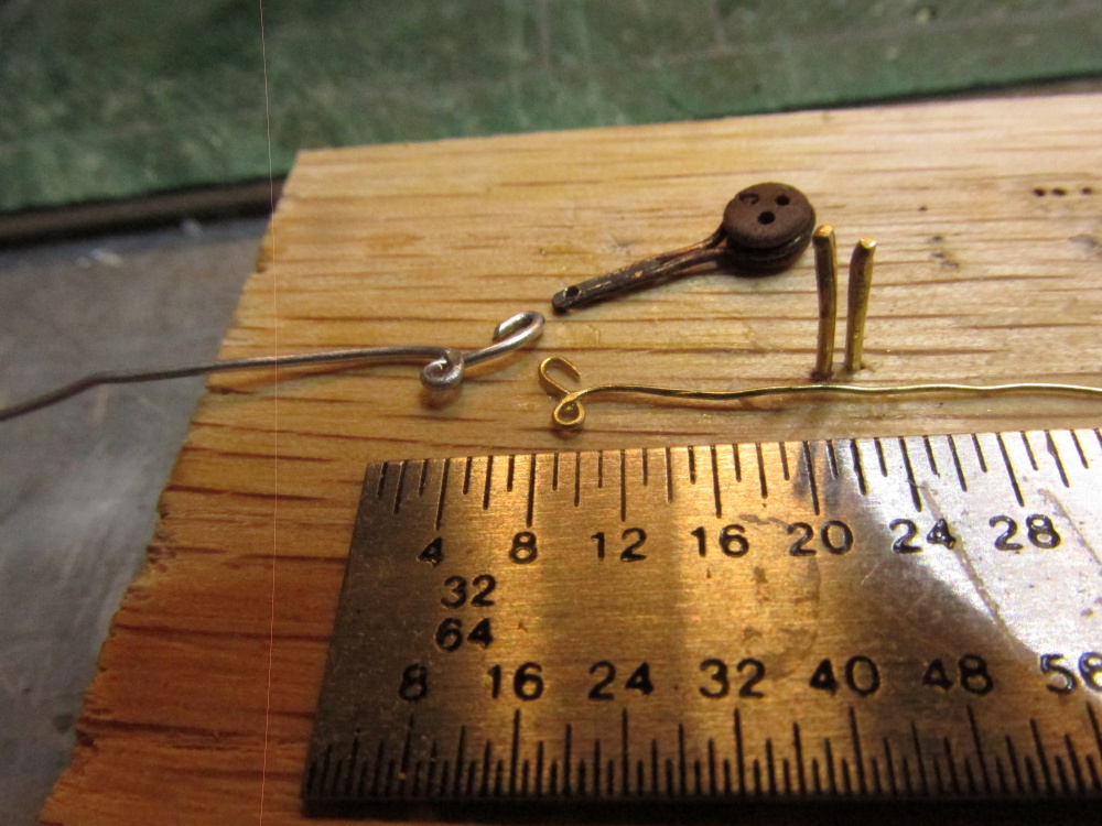
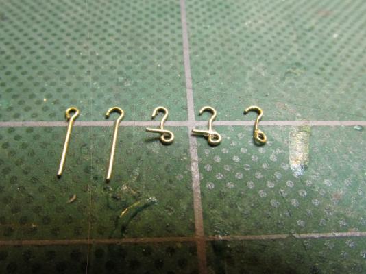
The hook was made by first opening up the eyelet and then wrapping it around two tiny nails used for planking to create the shape which you can see in the first picture. After the excess wire was trimmed off, the hook then was squeezed with a pair smooth jaw plyers to flatten it and then filed smooth.
- 974 replies
-
- 3
-
-
- rattlesnake
- mamoli
- (and 1 more)
-
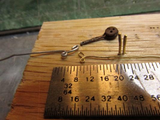
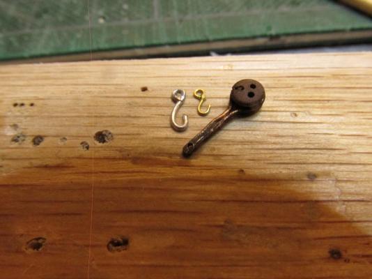
Then I tried using the smallest eyebolts I had - 1/16”. This appeared to work – the goldilocks zone. Here is a comparison:

- 974 replies
-
- 3
-
-
- rattlesnake
- mamoli
- (and 1 more)
-
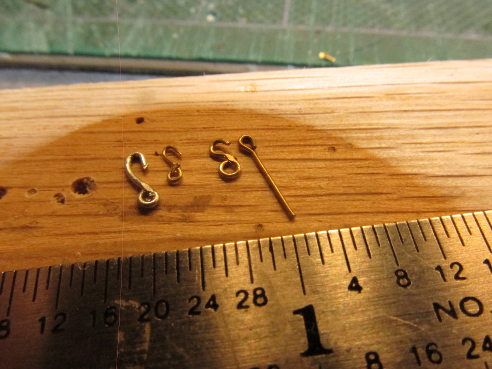
Chuck Passaro’s Syren Ship Model Company makes very nice laser-cut plastic hooks of various sizes. Unfortunately the physical hook of his smallest version will not pass through the hole I created when I made my futtock plates. That meant I had to make my own. First I tried some aluminum wire I had for the color – too thick. Then I tried some very fine brass wire and got a beautiful hook. Too bad the wire was so pliable, a simple tug and the hook would straighten out and fall off. I didn’t dare attempt to heat temper it for fear of burning it up – too weak.
- 974 replies
-
- 2
-
-
- rattlesnake
- mamoli
- (and 1 more)
-
Futtock Shrouds The futtock shrouds is connected to the futtock plates above via a hook and lashed to the shrouds below. Normally the metal hook connects to a metal thimble seized on the end of the futtock shroud. Due to the difficulty of constructing a thimble at this scale and the ability to even see it even if it were there, I have elected not to create these thimbles. The diagram below is from Rigging Period Ship Models, by Lennarth Petersson.
- 974 replies
-
- 3
-
-
- rattlesnake
- mamoli
- (and 1 more)
-
Now that I see more of the model I recognized it as a 1797 version built by Mark Antczak at 1:48 scale. The site is at.shipmodel.com
- 1,354 replies
-
- 2
-
-
- constitution
- model shipways
- (and 1 more)
-
GLakie - Are there more images the "72" version of the 1797 config."? I'm always looking for more sources to use when I finally start my attempt at the MS Constitution model. That probably won't be be for a year or two at the rate I building the Mamoli Rattlesnake. Is that model yours? It looks gorgeous.
- 1,354 replies
-
- 1
-
-
- constitution
- model shipways
- (and 1 more)