JSGerson
-
Posts
2,646 -
Joined
-
Last visited
Content Type
Profiles
Forums
Gallery
Events
Everything posted by JSGerson
-
 Thanks for the praise. It must be like watching paint dry at the pace that I'm going so I really appreciate it. Rigging is totally new to me. I have to understand the whys and hows before I do anything. I can sit and research or contemplate my naval for hours before I do anything; and that just might be tying a knot. 8-) Jon
- 974 replies
-
- 1
-

-
- rattlesnake
- mamoli
- (and 1 more)
-
The was a little twisting from the lashing but hopefully, that will get straightened out when the ratlines get installed later on.

- 974 replies
-
- 4
-
-
- rattlesnake
- mamoli
- (and 1 more)
-
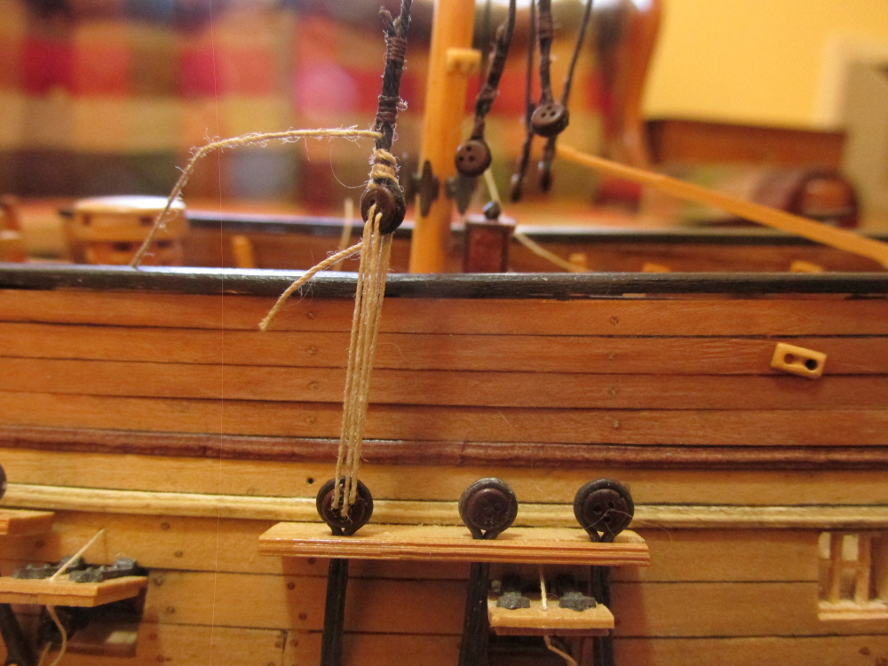
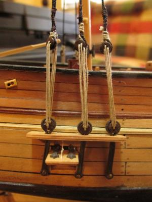
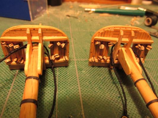
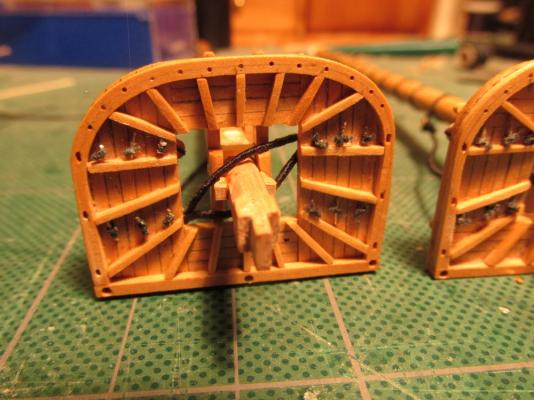
Following Mr. Lennarth Petersson’s Rigging Period Ship Models the deadeyes were lashed in the manner described. The image below is the Port side while the one above is the Starboard.

- 974 replies
-
- 3
-
-
- rattlesnake
- mamoli
- (and 1 more)
-
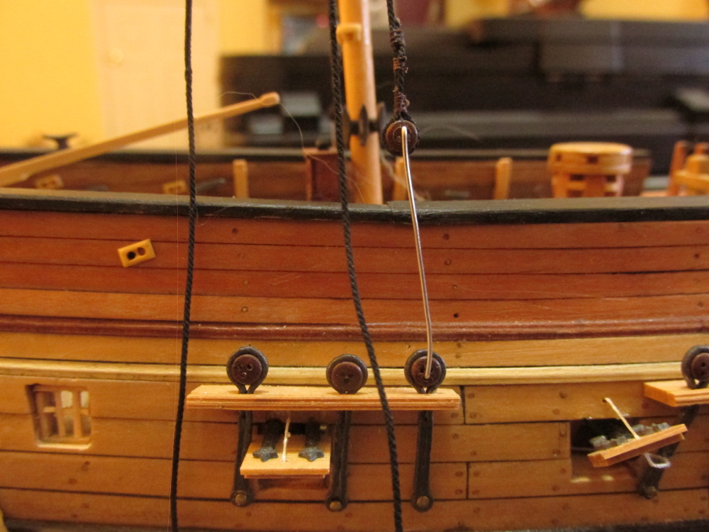
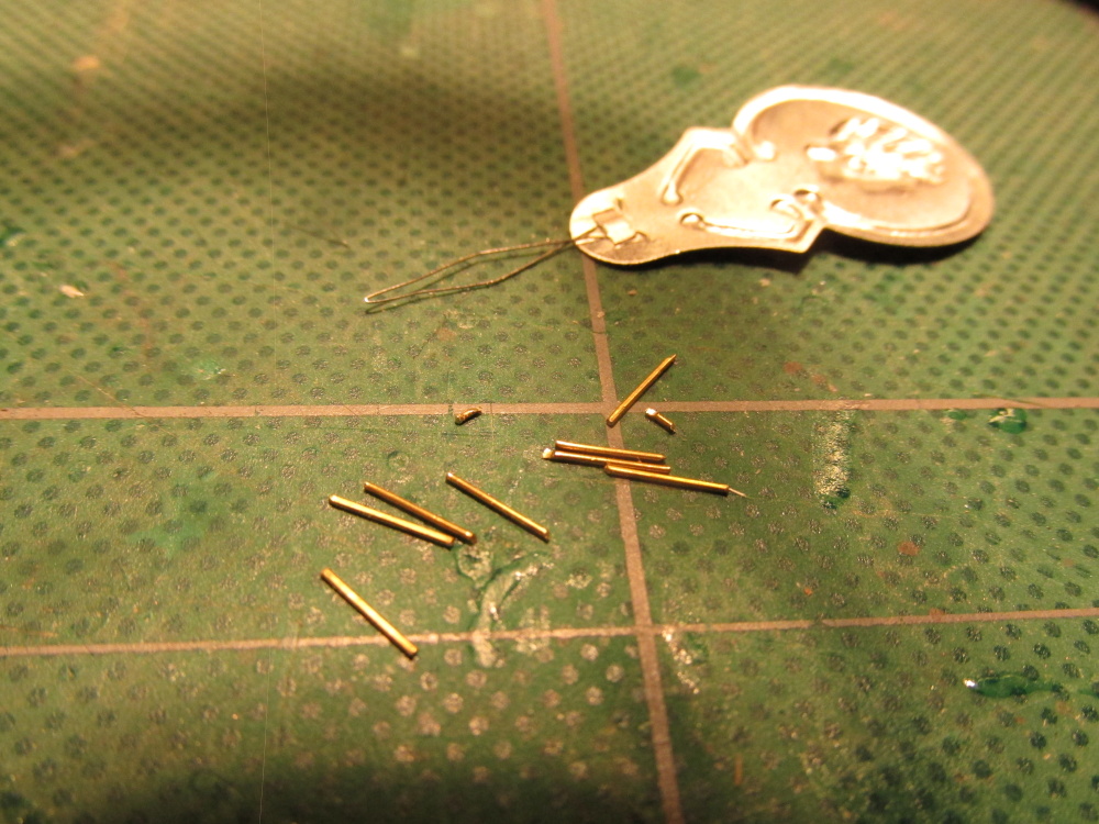
The first shroud in the group to be installed was the most forward one, the one made with the cut splice. To ensure that the deadeye at each end were on the same and proper height, two identical wires were cut and formed into a shallow U-shape, one for each end of the shroud. First one side had the deadeye attached and the U-shape wire attached. Then pulling the line taught the height of the other side was measured and the deadeye attached. The other U-shape held it in place. If the line remained taught with the wires, I was ready to lash the deadeyes.

- 974 replies
-
- 1
-
-
- rattlesnake
- mamoli
- (and 1 more)
-
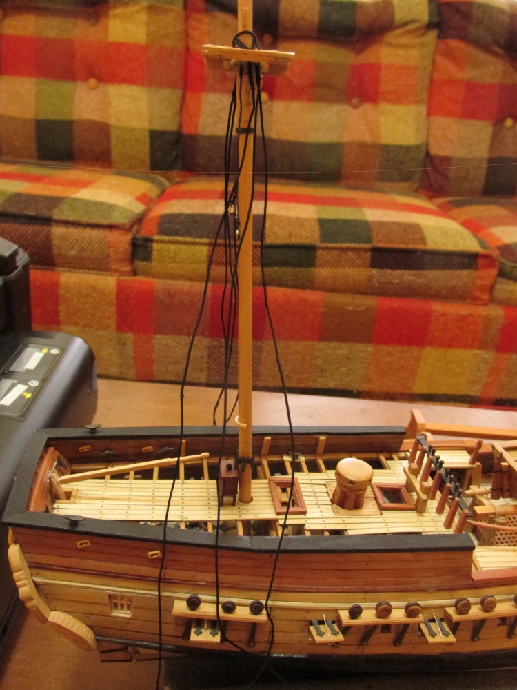
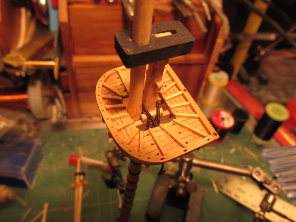
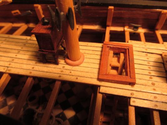
Also made long ago was the Quarter Deck Mizzen Mast Wedge which was installed into final position with the Mizzen Mast. The mizzen shrouds were now ready to be installed.
- 974 replies
-
- 4
-
-
- rattlesnake
- mamoli
- (and 1 more)
-
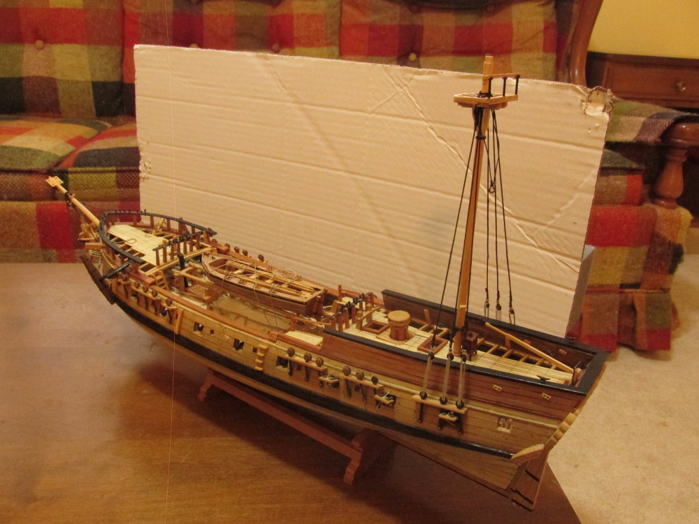
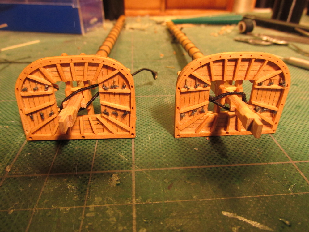
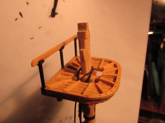
At this point I decided it was best if I installed the Mizzen Mast Top’s railing. The parts had been made earlier as documented in this build log.
- 974 replies
-
- 2
-
-
- rattlesnake
- mamoli
- (and 1 more)
-
Nicely done.
-
Silver Soldering Tools
JSGerson replied to bundybear1981's topic in Metal Work, Soldering and Metal Fittings
Jay, You need to look at the link you provided for more details about silver soldering. A number of images are missing. -
I found this part fun to do and really tried to put in a lot of detail. It turns out a lot of that detail (window "glass," fancy paneling, etc) get lost once all the decks are finished and furnished. If I were to do it again, yeah I'd do it again because that's me. What I'm trying to say is don't get hung up on stuff that won't get seen if you have problems with it. I my case it was the window "glass" frames. The "glass" really wasn't needed because nobody could see it which would have made the window framing much easier. (See my log for the details).
-
Jay: I have heard a lot about Mr. Hunt both good and bad, He is an "interesting" character. It's funny that you stated that he doesn't accept alternative ideas. In his Rattlesnake practicum, he did state that if you find a better way of doing something, go ahead and do it that way. So maybe he received so much "helpful" criticism, he just got pissed off because they didn't appreciate his efforts - who knows? Personally, I haven't had much dealings with him other than a few questions I posed which were answered decently, so I can't fault him. Your experience was obviously different than mine. I will take the good he has to offer and ignore the crap. This is no one right way of doing something and this forum proves it. I look forward to your completed Suggestion List as I know it will be helpful to all of us. Jon
- 732 replies
-
- 1
-
-
- constitution
- model shipways
- (and 1 more)
-
I am also using Mr. Hunt's practicum, in my case for the Rattlesnake and would not have even considered building it if it were not for Mr. Hunt's instructions. Like you, I have learned a lot. As an out right beginner in this area of model building, it was invaluable. To a more experienced builder maybe not so much. Yes there are deficiencies, omissions, errors, etc., but like all, nobody is perfect. Would I buy his practicum again, not only yes but I already did. I got lucky; a few years ago Mr. Hunt ran a short term sale. He offered ALL of his practicums for one total price of under $200 (I can't remember exactly). Since I wanted to build the Conny, I jumped at the chance and got them all. They make for a nice reference library.
- 732 replies
-
- 1
-
-
- constitution
- model shipways
- (and 1 more)
-
Out of curiosity I noticed that the design of your kit box is slightly different than mine. How old is the kit? Also, did you know that Mamoli is out of business due to a fire at their factory? How did you get HobbyMills' wood supplement? It was my understanding that Jeff Hayes and Robert Hunt had a falling out and that he no longer supplies the wood package. Jon
-
It's nice to see another Bob Hunt's Rattlesnake kit basher. I've been working on mine for about 4-5 years now, I'm real slow as this is my first POB. A word of caution. Mr. Hunt is human and like all humans, is prone to make mistakes. There are a just a few in the beginning chapters but more in the later ones. It seems he was building 3 other models at the same time as the Rattler each with deadlines. By the time I reached Chapter 9 he was skipping steps, cutting corners, and reducing details. In some case he only constructed items on one side of the model. In the rigging chapters he only showed examples and walked through the Mamoli instructions as he never actually rigged his model. All that being said, I could not have have built my model without his practicum. Dry fit everything, check dimensions, and read ahead to see how things fit together. All my triumphs and heartbreaks are documented in my build log. But don't forget to read everybody else's build log to see how they coped and build a library of reference material. Good Luck, and Happy Building! Jon
-
QUESTION: What color line is used for the deadeye lashings? I have seen both light color as well as dark. I was under the impression that standing rigging was coated with a tar like substance to make it more weatherproof yet I see more models with light color line than dark. Is this strictly for aesthetics or is there a real world reason? I saw on my my visit to the USS Constitution last Thanksgiving the lashings were dark.
-
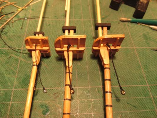
Now all of the mast tops are prepared for the shrouds. A set of shrouds for the Mizzen mast were constructed, one each pair each for the starboard and port. Where the shroud wraps around the mast is served to just below the bolsters and then a throat seizing is made to complete to top end of the shroud. At this point everything is still dry fit, neither the fighting tops nor the Mizzen mast is glued in place.

- 974 replies
-
- 3
-
-
- rattlesnake
- mamoli
- (and 1 more)
-
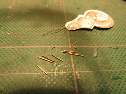
The kit plans show blocks suspended along the edges of the fight tops except for the Mizzen mast. Because I am including crows feet rigging, it was necessary to move the fasten points of the blocks located at the edges of the fighting tops to underneath the tops. As shown earlier when the tops were constructed, holes were drilled in the platform for that purpose. The blocks were stropped so that two lines came off the block, went through the platform hole and were fastened around a pin above the platform. The pin was made from the discarded trimmed stem pieces of eyebolts. No scrap is tossed out because it may have a future use.

- 974 replies
-
- 4
-
-
- rattlesnake
- mamoli
- (and 1 more)
-
Mizzen Shrouds Following a long with Mr. Antscherl, the Mizzen shrouds were next. He likes to work from the stern forward as opposed to others who work from the Bow to the stern. Because there are an odd number of Mizzen shrouds three to be exact, the foremost of them is constructed like the Burton Pendants, with a cut splice. Mr. Antscherl stated that the foremost shroud is normally served over its full length to protect it from chafing by the lower sail courses However since the Mizzen mast does not have sails spread on the cross-jack yard, it was not served over its full length. All of the shrouds are served over the center quarter of every shrouds pair’s length according to Mr. Antscherl. This was done, but unless you are looking for it and are very close to the rigging, it is almost impossible to see due to both the shroud and serving line being black in color.

- 974 replies
-
- 3
-
-
- rattlesnake
- mamoli
- (and 1 more)
-
It’s been a while since my last post so I suppose you were expecting a lot of progress? Meet Mr. Slower than Drying Paint. Slow, yes, but some progress. I completed the remaining Burton Pendants installed them onto their respective masts
- 974 replies
-
- 4
-
-
- rattlesnake
- mamoli
- (and 1 more)
-
It's amazing what I have stashed away from my research for the Conny build. I found: 1812 Model build by Ken Thomsen using Model Shipways' kit. (6 windows) Unfortunately the site where his pictures were located (Shipwright's Journal) are no longer posting them, but if one googles "constitution 'ken thomsen,'" using the image search, you can still see the images. 1812 Model at the Smithsonian (6 windows) The Revell 1:96 model was based on this
-
I stand corrected
-
I ran across this beautiful rendition of the 1812 Conny by Mark Antczak. He has eight windows!! http://www.shipmodel.com/models/constitution-old-ironsid
-
Thanks Fletch, I've sent a PM to Popeye2sea and now I can only hope for the best.
-
I placed an order to the USS Constitution Museum for some Constitution Wood and received a block 2 1/2" square x 3/4" thick for $5.50; not much to work with. How did you get such large pieces? I would love to incorporate some of the real ship's wood in my model when I start it a few years hence but with what I have, all I'll be able to do is mount the copper Constitution Medallion I also have made from her copper sheathing. There should be a new supply of wood once the new restoration gets into full swing this year, so hopefully there should be larger piece available ideally at reasonable prices.
-
Very nicely done!