JSGerson
-
Posts
2,646 -
Joined
-
Last visited
Content Type
Profiles
Forums
Gallery
Events
Everything posted by JSGerson
-
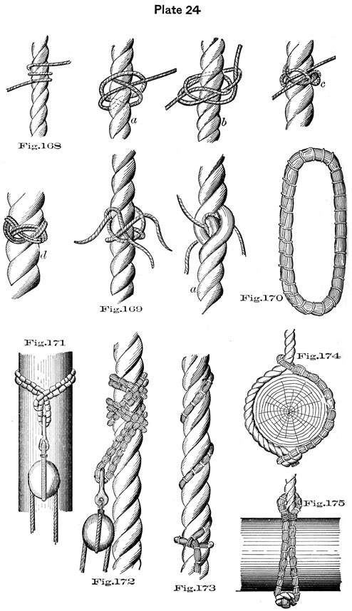
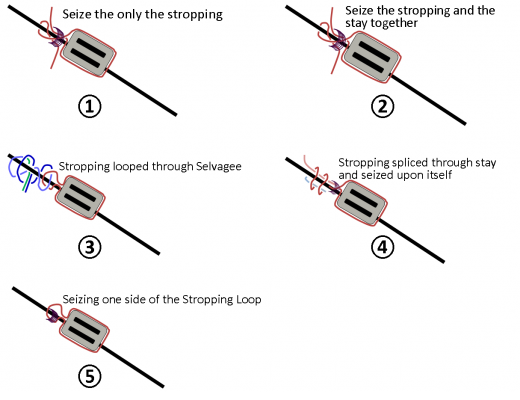
 You will notice in figure 172 how a block is attached to a stay, in this case, with a shackle (or hook?) using a Selvagee (Figure 170). “A Selvagee is made by warping. rope-yarn, spun-yarn, or small stuff, according to the size required, and marling down.” If I substitute the shackle for a stropping loop I have what I’m looking for. The next problem is: how to model it at 1:64 scale? If I tried to do the actual rig as illustrated, the result I believe would be too complex and too bulky. The answer of course is to simulate it. To do that, I chose to use Method 4. One of the stropping bitter ends will be spliced through the stay and seized upon itself while capturing the other bitter end. That should satisfy my need for some sort of mechanical joint as well as make it look somewhat like a Selvagee was used. So much for theory; it didn’t work out that way. I forgot to take into consideration that that area of the main stay was served. Trying to penetrate that served rope with a needle in that confined area is almost impossible, and if perchance I should break the serving thread while trying to pierce the stay, the whole serving could unravel. So in the end, the block was just looped over the stay as originally illustrated in the plans very similar to method 1, which by the way was suggested by the Practicum’s author himself, Robert Hunt.
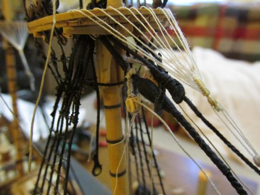
- 974 replies
-
- 3
-

-
- rattlesnake
- mamoli
- (and 1 more)
-
I did some research as well. I found the following illustration in the 1891 Text-Book of Seamanship, the Equipping And Handling of Vessels Under Sail Or Steam For The Use of The United States Naval Academy By Commodore S. B. Luce, page 50, plate 24. The book is a bit more modern than the 1781 Rattlesnake but I don’t think the basics had changed that much.

- 974 replies
-
- 1
-
-
- rattlesnake
- mamoli
- (and 1 more)
-
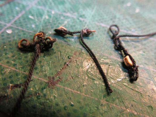
Rigging the Stay Blocks I received numerous suggestions as to attaching the double block to the stay. Thanks you all for your comments. In the image below, I’ve tried to illustrate as best I could the methods (as I understood them) you have suggested:
- 974 replies
-
- 3
-
-
- rattlesnake
- mamoli
- (and 1 more)
-
Very nicely done!
-
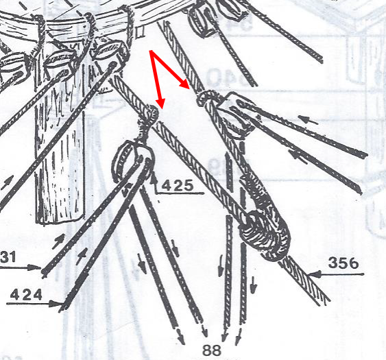
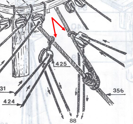
QUESTION I have to fasten double blocks to a stay as shown in the diagram below (red arrows). As indicated, it appears that the blocks just have a simple stropping loop at the top which goes around the stay. That would mean the blocks are held in position and have enough holding power to counteract the forces applied to it by pure friction. I don’t buy it. There has to be some mechanical method to take the load. Is this diagram correct? or… Is there a special type of knot or splice I should know about? Does anyone have an answer?
- 974 replies
-
- 3
-
-
- rattlesnake
- mamoli
- (and 1 more)
-
Don't worry about the nick...in the end you won't see it. As a matter of fact you won't see most the this partition due to lack of light and and the conjestion when the model is done. I put a lot of effort to make my partition look nice, but I can barely see it now.
- 481 replies
-
- 2
-
-
- rattlesnake
- model shipways
- (and 1 more)
-
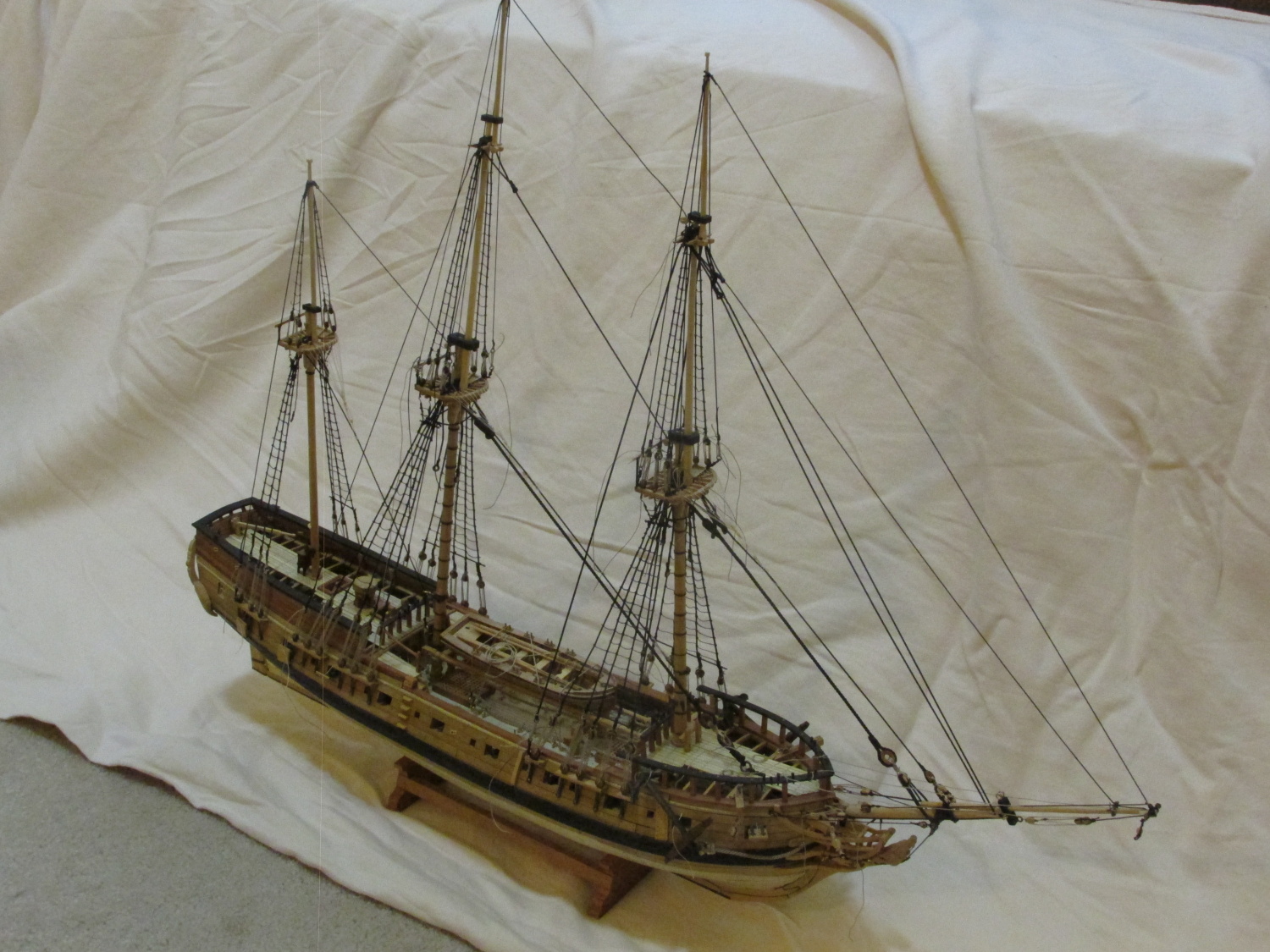
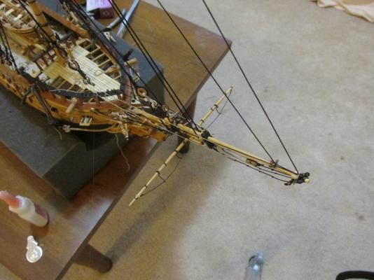
At this stage, the yard is just hanging in the breeze with no additional lines for stability. That’s the next set once I figure out where all those lines go.

- 974 replies
-
- 6
-
-
- rattlesnake
- mamoli
- (and 1 more)
-
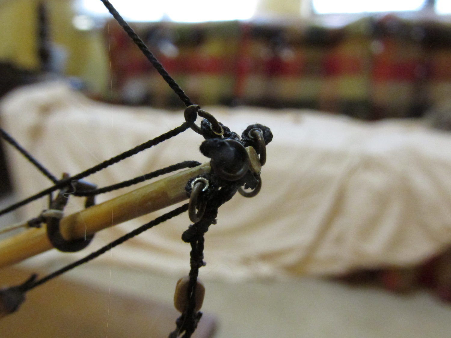
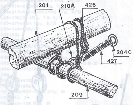
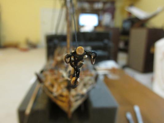
Also at that time, although not documented in this build log, the fabrication of the sling that suspends the Spritsail Yard from the bow sprit was initiated. Basically what was done at the time was to serve a length of 0.40mm beige rope supplied from the Mamoli kit with black thread rendering the rope black in color. (No use in using my fine Syren rope if it’s to be covered in served line.) A seized loop was formed at one end, wrapped around the center of the yard and seized again to itself. Coming back to it a year later, I realized that the loop was too bulky and large so it had to be done over. Using the technique demonstrated by Davis Antscherl at the last Nautical Research Guild Convention, I created a split loop which was smaller and a lot less bulky. Again the loop was seized to itself, wrapped over the bowsprit and under the yard and back where it was seized to itself, over the bowsprit again and through the initial loop and back. It was then seized to itself one last time. (No. 426 in the diagram below) Let me tell you that was no mean feat. Trying to thread the sling lines around the existing lines as well as the seizing thread lines without getting lost is enough to make you cross eyed!
- 974 replies
-
- 3
-
-
- rattlesnake
- mamoli
- (and 1 more)
-
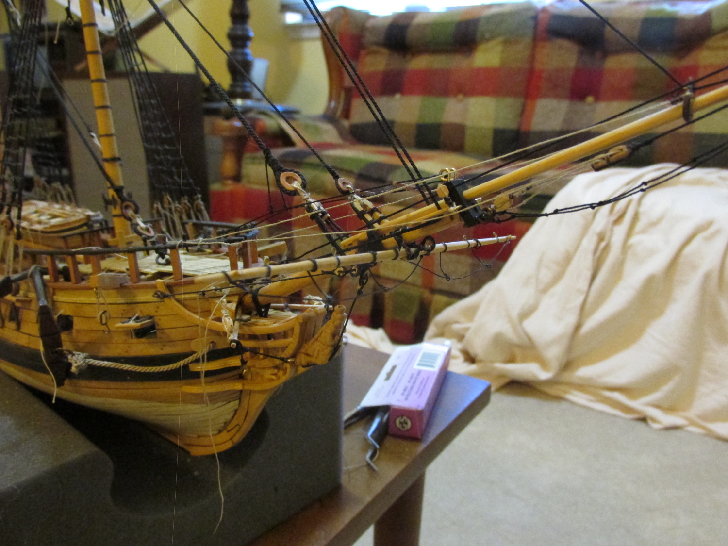
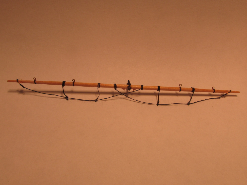
Spritsail Yard Well, I’ve hit another milestone: the installation of the first yard on the model, the Spritsail Yard. If you may remember so long ago last October 2014, both the Spritsail Yard and the Spritsail Topsail Yard were completed and set aside.
- 974 replies
-
- 3
-
-
- rattlesnake
- mamoli
- (and 1 more)
-
I know exactly how you feel Greg. Take a look at the second paragraph of my very first post for my Rattlesnake: Jonathan
- 1,354 replies
-
- 4
-
-
- constitution
- model shipways
- (and 1 more)
-
It's been a while since I last check in on you. Your model looking good. I thought I should point out to be careful about your gun port doors. I would have recommended that you install those at the last convenient point your could. I had all but one of my doors knock off during routine handling of the model. I won't put them back on till I feel I won't knock them off again or if I feel putting them on later would be harder.
- 481 replies
-
- 3
-
-
- rattlesnake
- model shipways
- (and 1 more)
-
Maybe I can answer that question for you Ken, per the instructions in Bob Hunt's practicum he states: Two vital items are needed; a single edge razor blade and some very thin cutting disks. I'm not talking about those fat disks that Dremel makes for their Dremel tool. I'm talking about wafer thin disks. You can purchase these disks from a company called [Dedeco] International, Inc. Their address is Rt 97, Long Eddy, NY 12760 and their phone number is (914) 887-4840. You will need their super thin separating discs. You can buy a package of 25 (#5173) or 100 (#5183) and they also sell shanks for these thin discs. You might be able to get something like these elsewhere but this is where I got mine. He also states: You use your Dremel tool with the fine cutting disk in it to cut the profile into the razor blade. These disks are very fragile and easy to break so be careful and wear some eye protection. I can confirm, they are very fragile if you apply any pressure on the face of the cutting disc.
-
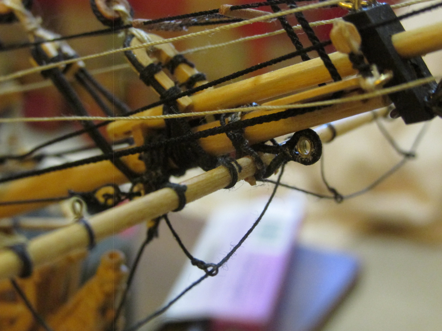
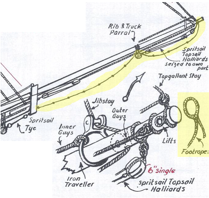
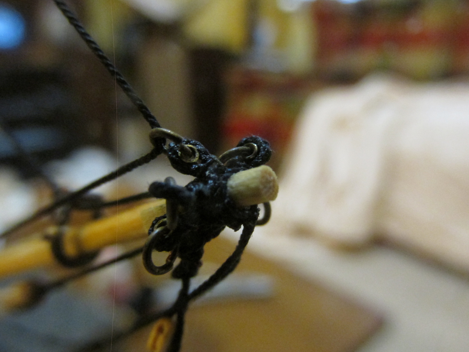
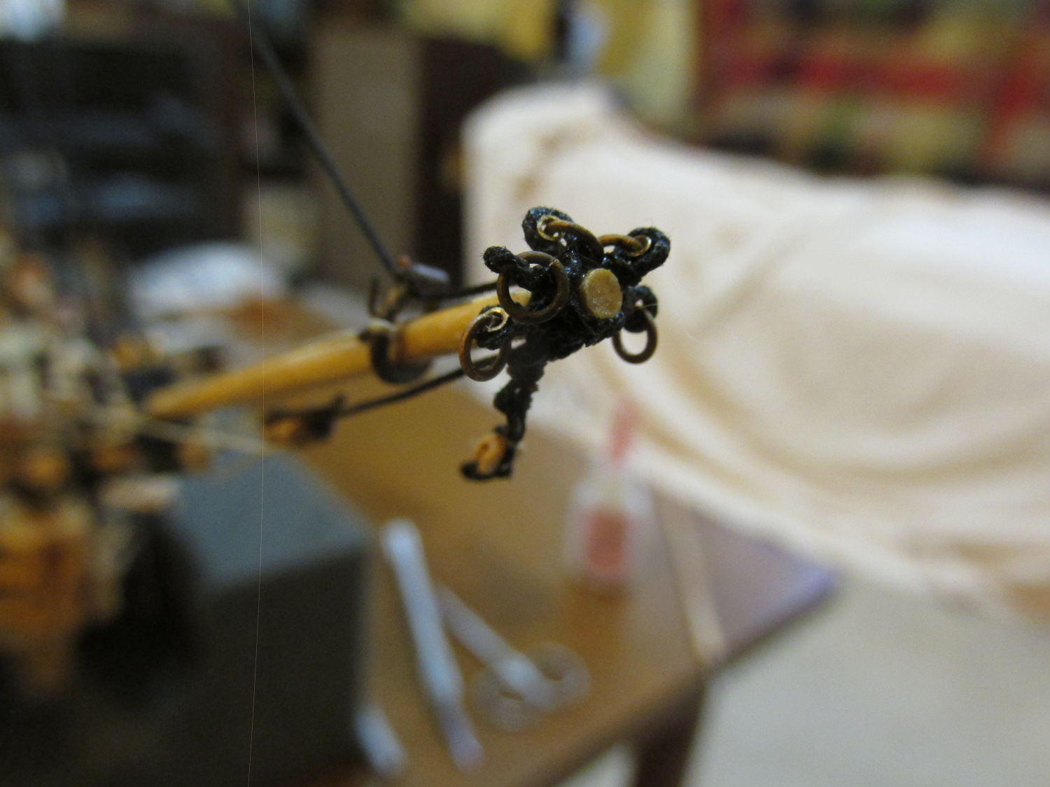
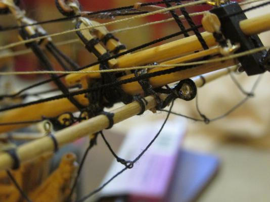
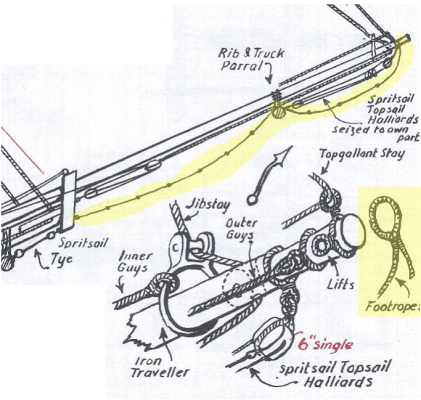
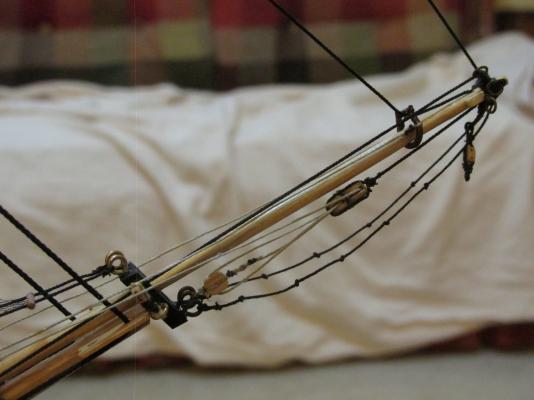
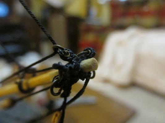
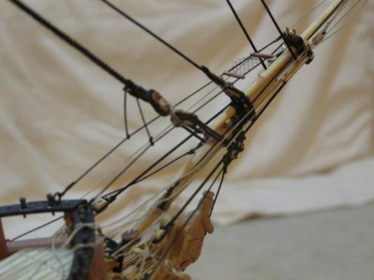
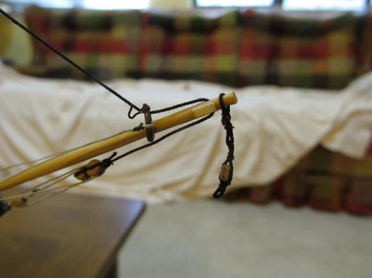
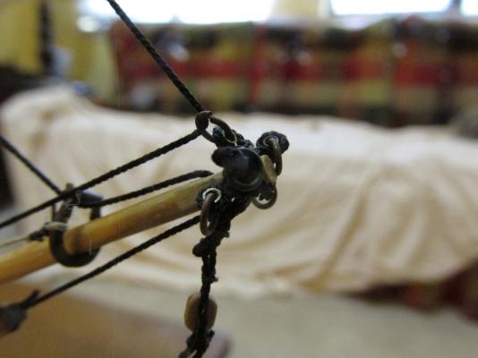
The footropes are supposed to be long enough to hang in an arc. According to Antscherl, the center of the arc is about three feet (~½”) below the jibboom. However, his footropes hang free because his model does not have a Spritsail Topsail Yard. On the Rattlesnake, it does have a Spritsail Topsail Yard which will be suspended in the middle of the jibboom. The plans show the footropes going above the yard. It appears the footropes slide (as opposed to being fastened to the jibboom) over the Spritsail Topsail Yard allowing the footrope to self-adjust as the yard moves along the boom. The footropes were installed with an initial three foot hang. How much they will finally hang down will depend how they drape over the yard once it is installed. Note the last image of the jibboom tip shows how crowded it gets. I had hoped to show the detail in there, but the black rope just sucks up the light so you can’t see too much.
- 974 replies
-
- 5
-
-
- rattlesnake
- mamoli
- (and 1 more)
-
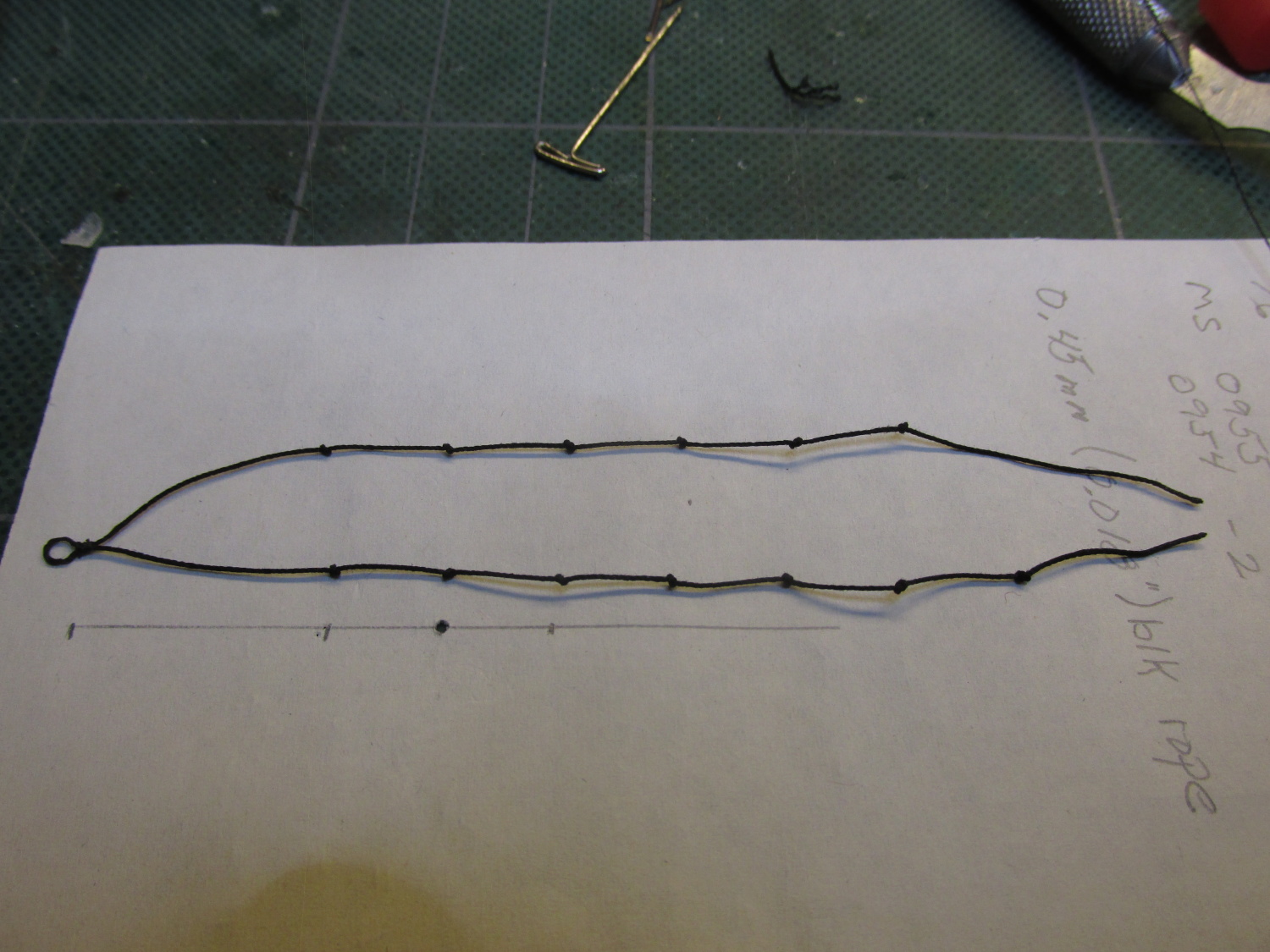
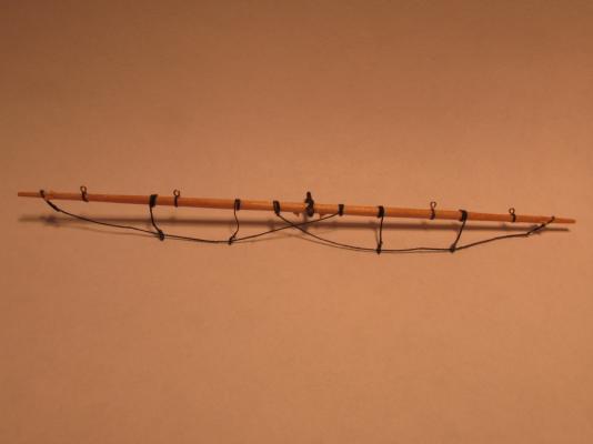
The footropes, one on each side of the jibboom, terminate at the cap at eyebolts. Starting about 5 feet (~7/8”) from the jibboom tip, knots are placed every two feet (3/8”).

- 974 replies
-
- 2
-
-
- rattlesnake
- mamoli
- (and 1 more)
-
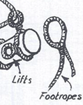
Jibboom footropes Like the horses described above, the jibboom footropes were made from black 0.30mm rope. There is a nice picture on the MS plans of how the footropes are constructed around the tip of the jibboom, which you may recognize from a previous posting.
- 974 replies
-
- 1
-
-
- rattlesnake
- mamoli
- (and 1 more)
-
Finally, the assembly was put in place, lines adjusted, and secured down.
- 974 replies
-
- 7
-
-
- rattlesnake
- mamoli
- (and 1 more)
-
The horses were further secured on the model to the forestay with a line coming off 90° from the horse. Here I used black 0.20mm Syren rope. They were attached to the horses with a pseudo splice. Since I didn’t know were along the horse it would secured, I left the splice unglued and the line excess uncut.

- 974 replies
-
- 3
-
-
- rattlesnake
- mamoli
- (and 1 more)
-
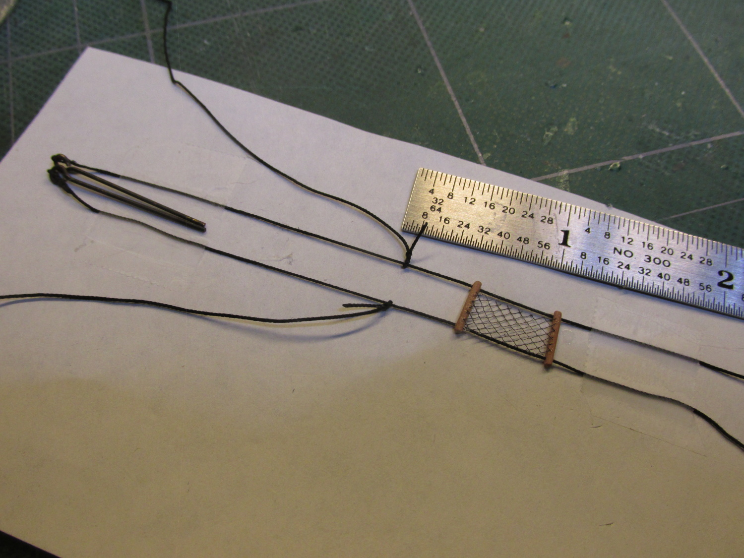
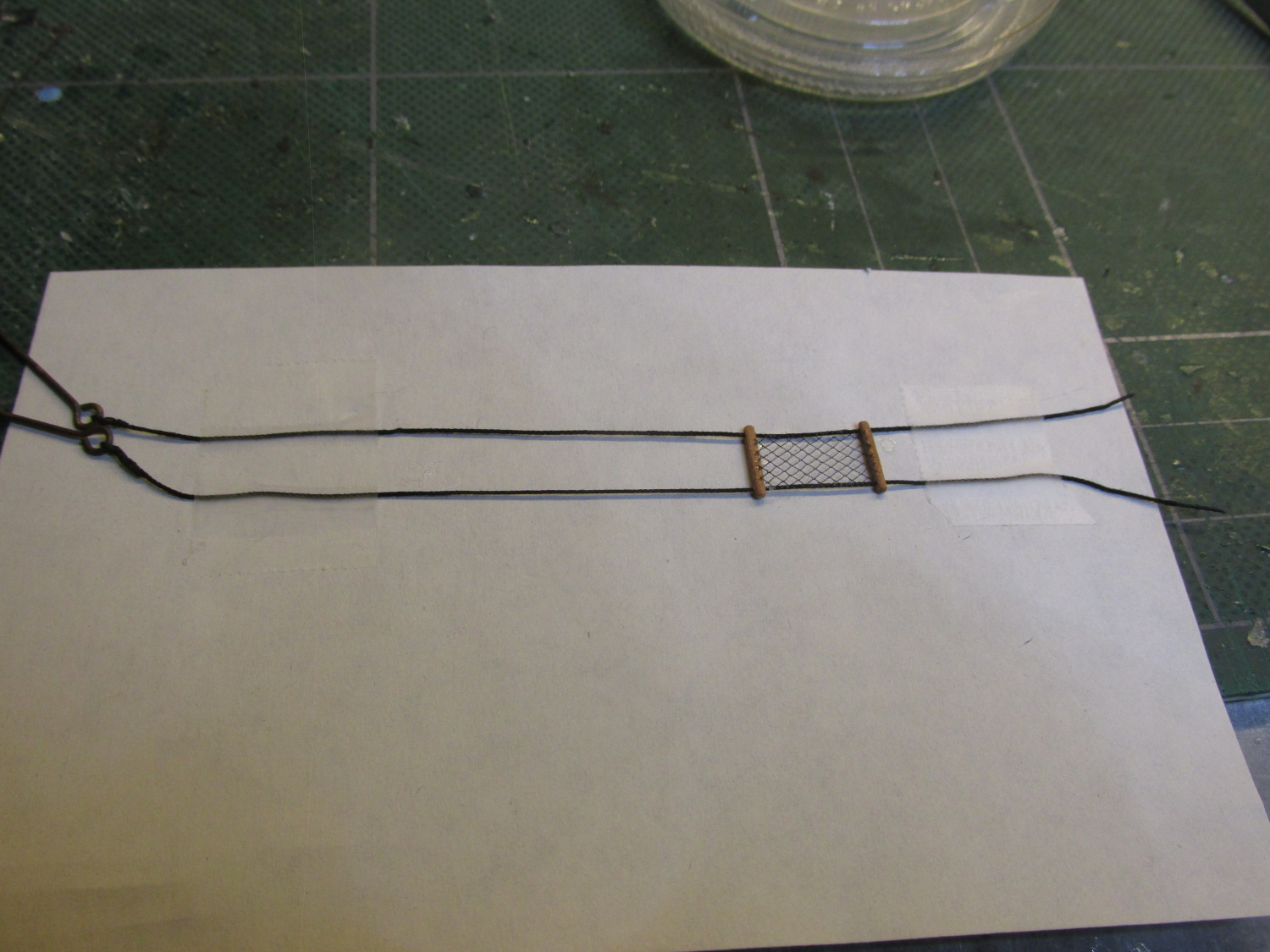
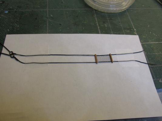
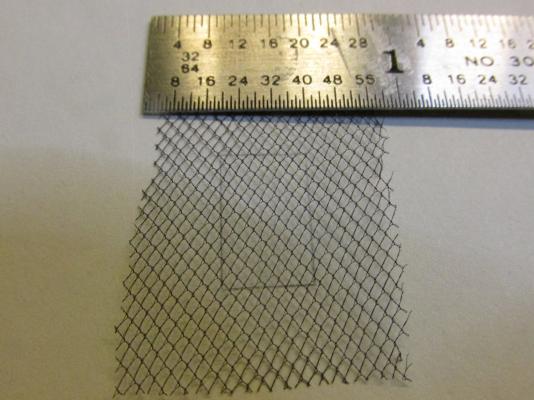
A pattern of the net was drawn on a piece of paper and the tulle was taped down at approximately 45° to the vertical of the pattern. My initial thought was to cut the tulle so that corners of the diamond pattern would form a zig-zag edge. Then I would wrap thread through the edge diamonds and then secure it to the staves and eventually the horses. As you can see from the close-up image above, the material is not just a simple crisscross of thread. I didn’t have any thread fine enough to come close to the thread in the tulle and what I did have (polyester mono filament thread which came the closest to being thin enough) was very stiff. Trying to hold these tiny parts and manipulate them to conform to what I wanted was like trying to herd a bunch of drunken cats while on crutches…at night. I gave that idea up soon enough. At this point I went to the Nautical Research Guild’s yearly conference, which this year was held at Mystic Seaport, CT. I had a good time. There, I saw an award winning model (forgive me, but I did not record the model or its maker) with the fore topmast staysail netting. He just glued the net in place. If he could do it, so could I. The assembly was taped down and the netting was glued to the stretchers using G-S Hypo Fabric Cement I got from Model Expo. It has the look, feel, and smell of airplane glue, but dries clear and is flexible.
- 974 replies
-
- 4
-
-
- rattlesnake
- mamoli
- (and 1 more)
-
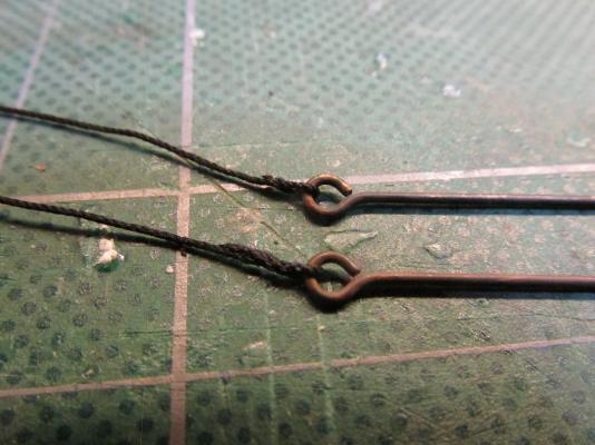
Using black 0.30mm Syren rope for the horses, one end of each line was secured to a blacken eyebolt using a pseudo splice. The open ends were then threaded through the stretchers. They would eventually be secured to the eyebolts already on the bowsprit cap.
- 974 replies
-
- 2
-
-
- rattlesnake
- mamoli
- (and 1 more)
-
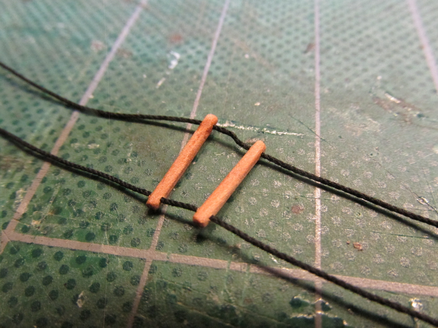
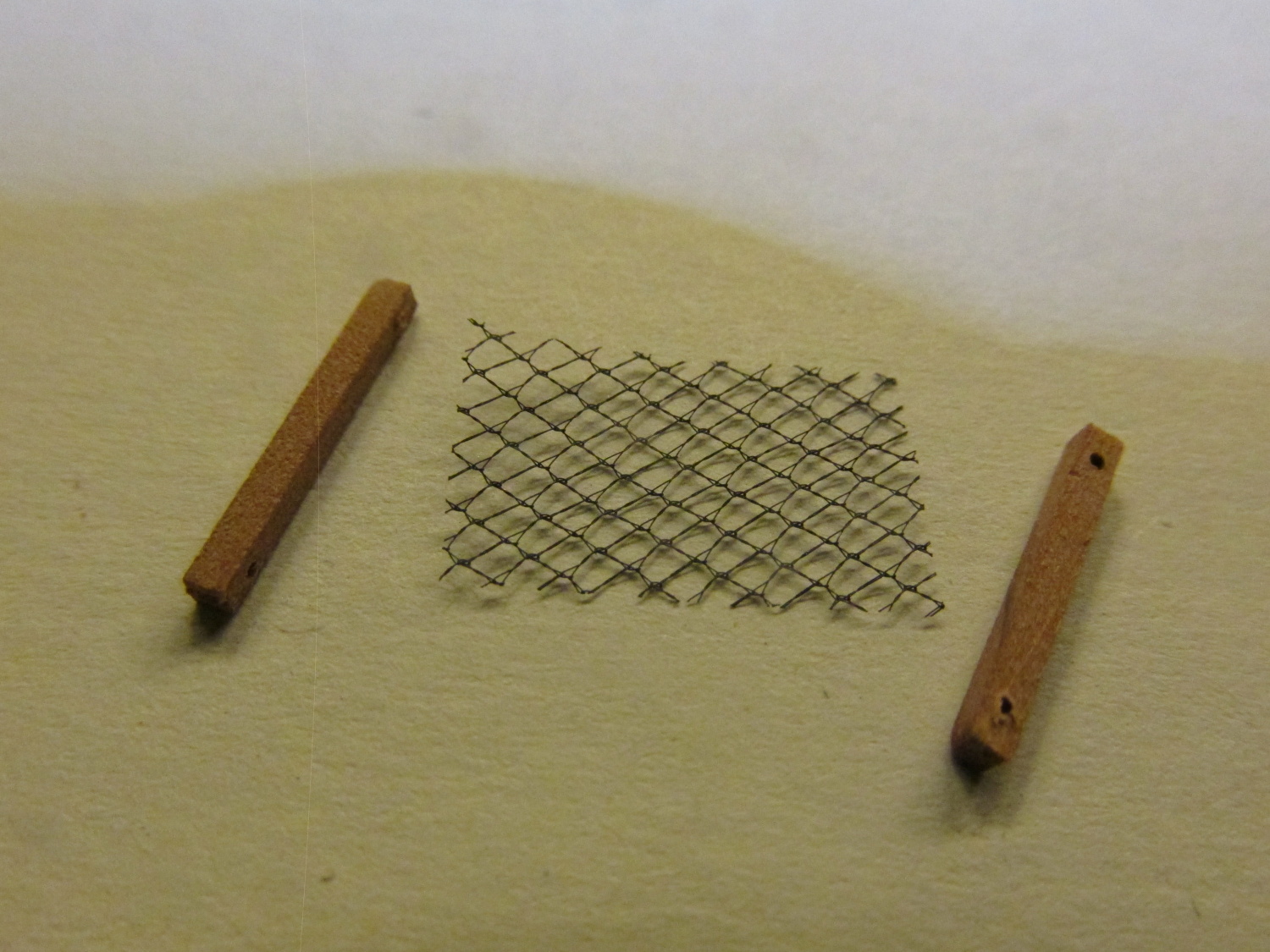
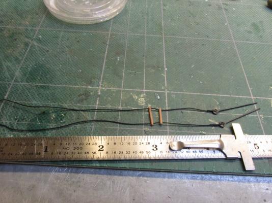
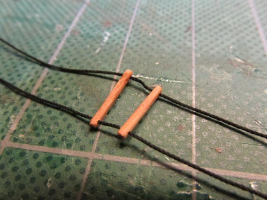
Using a piece of 1/64” square boxwood stock, two staves to act as stretchers were formed each with holes to allow the horses to pass through. Once the holes were drilled, the square staves were rounded into rods.

- 974 replies
-
- 1
-
-
- rattlesnake
- mamoli
- (and 1 more)
-
Bowsprit Horses and Fore Topmast Staysail Netting Continuing to follow David Antscherl, now was the time to create the bowsprit horses, and although not shown on any of my plans, the fore topmast staysail netting. The netting is used to store the topmast staysail and is located on the bowsprit horses between forestay and the foretopmast preventer stay. Mr. Antscherl was very clear that the diagrams in Darcy Lever’s The Young Sea Officer’s Sheet Anchor, Lee’s The Masting and Rigging of English Ships 1625-1860, and Peterson’s Rigging of Model Ships¸ were incomplete. They only showed the initial zig-zag construction of the netting and not the final result which was a diamond shaped netting. David went so far as to reproduce this netting for his model; I, being of sound mind and body, elected not to. Instead I bought some tulle in black and off-white at Hobby Lobby. It’s a sheer often stiffened silk, rayon, or nylon net used chiefly for veils. It’s not perfect, but it was all that I could find in my area. Both pieces set me back a grand total 0.30 cents for more material than I will ever use in a lifetime.
- 974 replies
-
- 1
-
-
- rattlesnake
- mamoli
- (and 1 more)
-
Martin, I'll be heading out next Tuesday and checking in Wednesday. I'll see you Wednesday or Thursday!
-
The first to be attached was the block assembly, followed by the double eyelets, and finally the triple eyelets. The block assemble was attached with a loop through an eyelet and pulled tight. The multiple eyelet assemblies had to be installed in steps. In actuality, the rope ends were spliced or lashed together which at this scale was impossible to do. First, an assembly was orientated to the proper position and then a touch of glue was added at the top to hold it in place. The two ends were cut so that they would just meet under the bowsprit and butt together. First one end the given a touch of glue and then the other was made snug and glued into place. The fourth item, the footropes was not added at this time but will be added later. That will be made from thick thread so there is just enough room left to secure it.

- 974 replies
-
- 5
-
-
- rattlesnake
- mamoli
- (and 1 more)
-
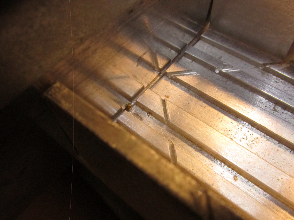
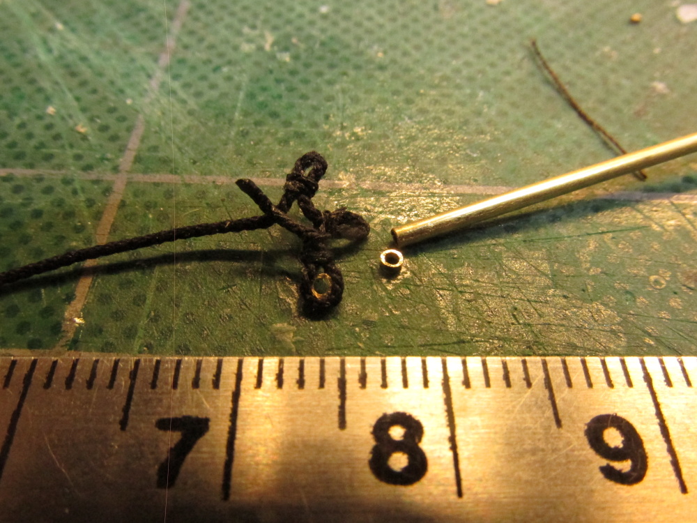
However I chose to follow Mamoli for the construction of these items, in particular the addition of thimbles in the eyelets. They were cut from 3/64” brass tubing. You can just see it against the saw blade in the 90° groove.


- 974 replies
-
- 4
-
-
- rattlesnake
- mamoli
- (and 1 more)