JSGerson
-
Posts
2,646 -
Joined
-
Last visited
Content Type
Profiles
Forums
Gallery
Events
Everything posted by JSGerson
-
 My, you've been busy! You are moving right along which I can't say for myself. She's going to be a fine model.
 -
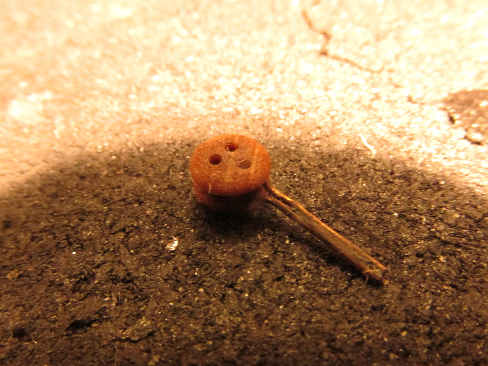
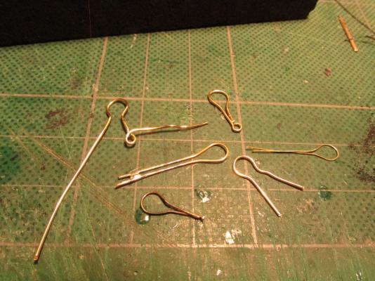
The whole assemble was given a blacken bath and water rinse which didn’t affect the wooden deadeye. Now all I have to do is make 17 more without going crazy.

- 974 replies
-
- 3
-

-
- rattlesnake
- mamoli
- (and 1 more)
-
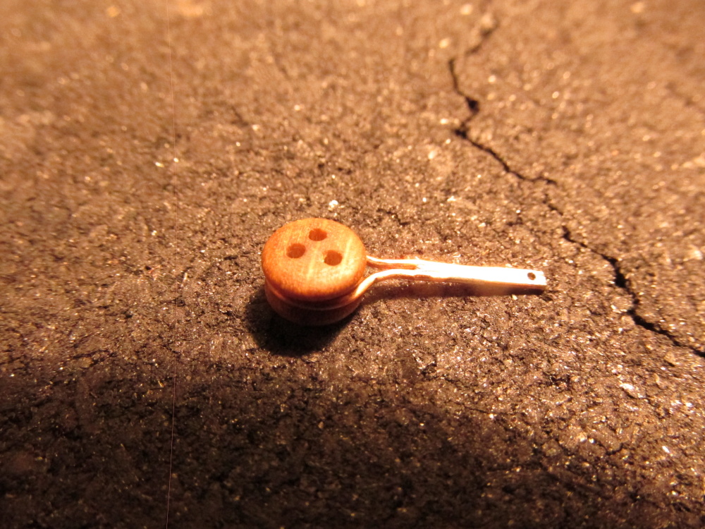
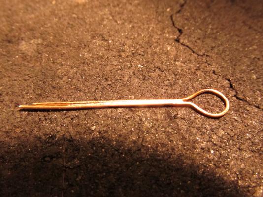
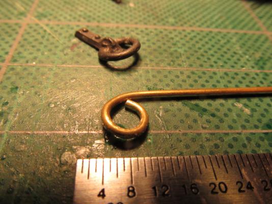
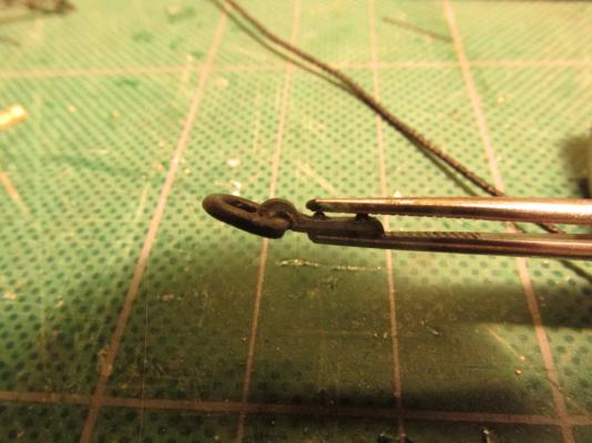
Once the deadeye was positioned, the wire was squeezed closed. When installed into the top, the unsoldered area will be covered by the top and secured closed by the small opening. The tail was then trimmed to length and a 1 mm hole was drilled at the end of the tail for the hook connection.

- 974 replies
-
- 4
-
-
- rattlesnake
- mamoli
- (and 1 more)
-
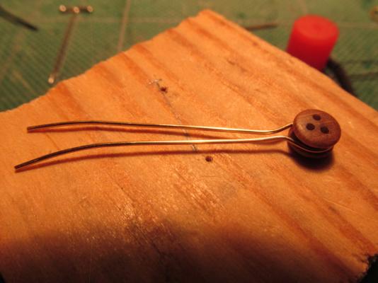
After a couple of attempts, I was able to solder the legs together yet leave enough unsolder so that I could pry the opening wide enough insert the deadeye.
- 974 replies
-
- 1
-
-
- rattlesnake
- mamoli
- (and 1 more)
-
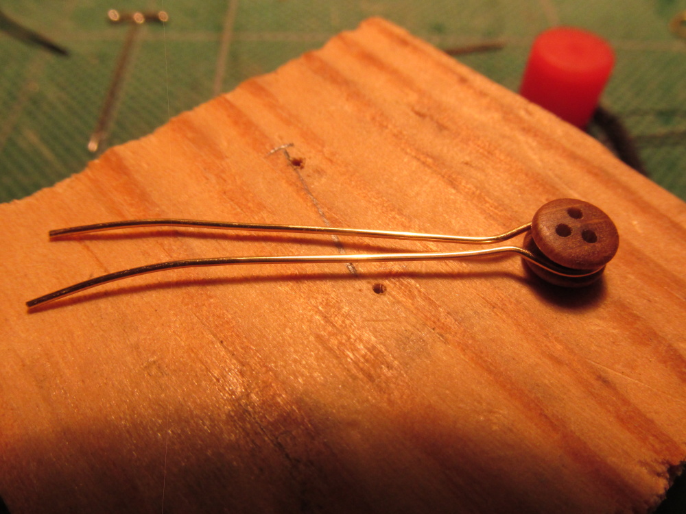
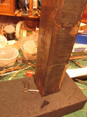
The deadeye was removed and the wire was then given its acid cleaning bath and water rinse. The wire was then placed on a very simplistic jig consisting of three pins and a 3-pound hunka-chunk of nuclear grade stainless steel…scrap (approx. 1” square x 6 inches). This was my souvenir that I liberated from a scrap heap at the now brand new, never used, decommissioned Shoreham nuclear power plant on Long Island NY were I was a Nuclear Quality Control Inspector back in the late 70’s. But that is another story (see link). The metal chunk kept the wire tail flat and butt-up together while silver soldering.
- 974 replies
-
- 2
-
-
- rattlesnake
- mamoli
- (and 1 more)
-
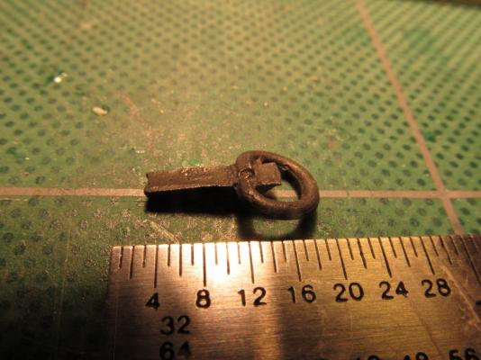
I finally worked out this method: First I had to sand the strip of wire I was to use to remove its protective coating. That coating would prevent blackening. Then I bent the wire around the deadeye to give the general shape.
- 974 replies
-
- 2
-
-
- rattlesnake
- mamoli
- (and 1 more)
-
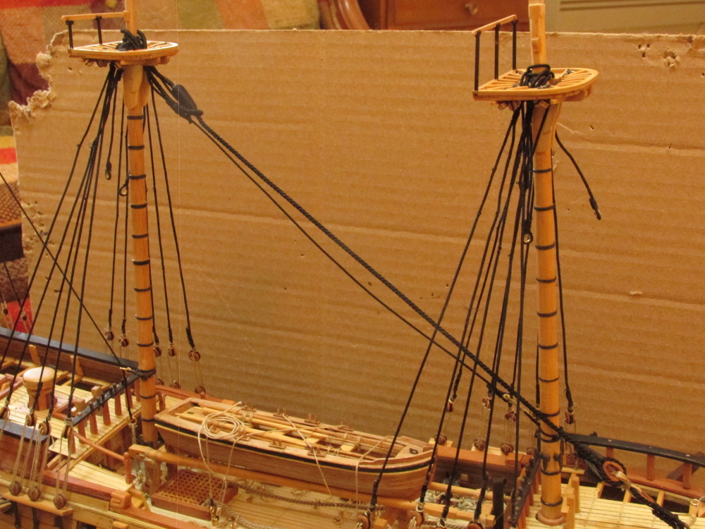
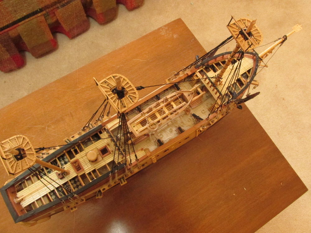
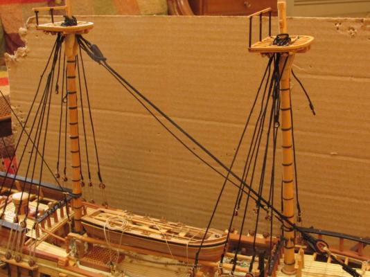
Fighting Top Deadeyes I decided at this point I had better install the deadeyes and straps on the fighting tops before I introduce any more rigging to the masts and make my life more difficult. I had the foresight to install the blocks on the tops before they were installed but in my enthusiasm to start the rigging, I neglected to install the deadeyes and straps as well. When creating the tops, I tried to follow as closely to the plans as I could, maybe too close. I made the openings for the deadeye straps quite small about 1 x 2 mm. I quickly realized that I could not increase the openings now that they were on the model. After numerous attempts to create a strap that would embrace the deadeye and fit through the opening, I had to discard any idea of making a loop at the bottom of the strap for the hook connection, discard the idea of using a larger gauge of wire bigger than 0.5 mm even though I thought that would look better, and finally any idea that this would be easy. The wire I ended up using was 0.5mm “beading wire” (the pkg. did not state its metallic composition). I could not find brass wire at the Hobby Lobby in my town, the only hobby store around.
- 974 replies
-
- 1
-
-
- rattlesnake
- mamoli
- (and 1 more)
-
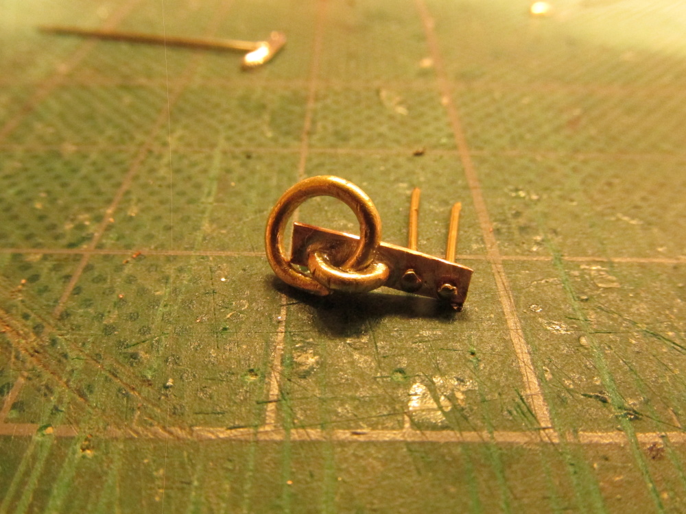
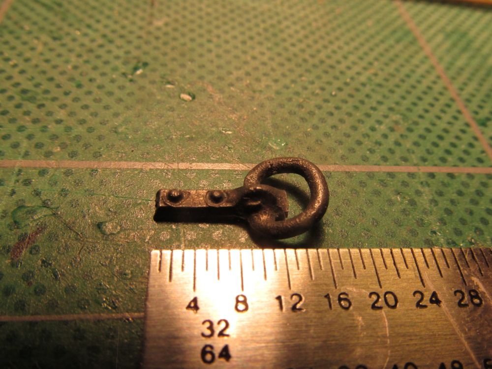
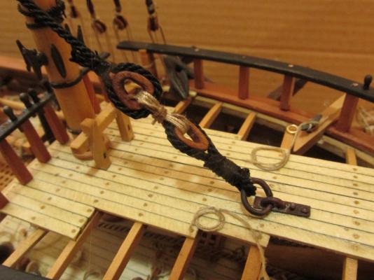
The finished assembly is shown in the following images.
- 974 replies
-
- 4
-
-
- rattlesnake
- mamoli
- (and 1 more)
-
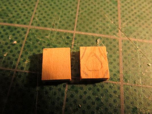
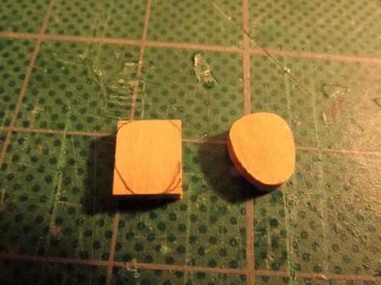
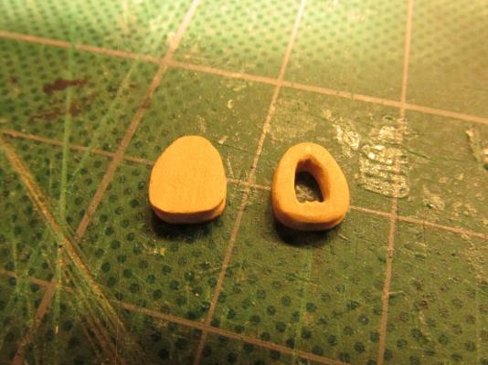
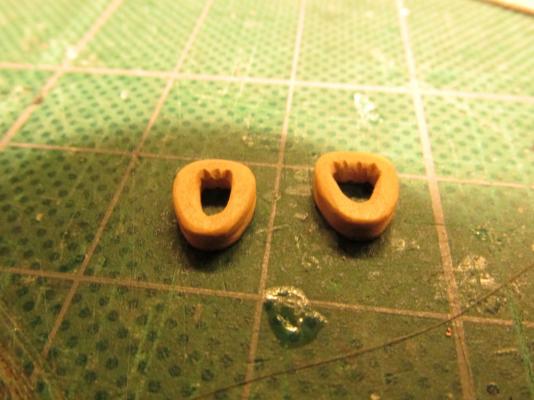
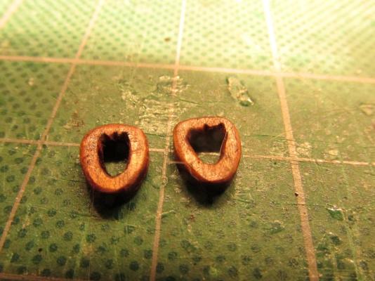
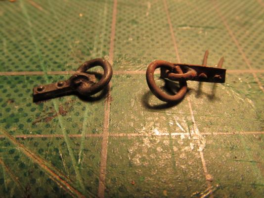
At the other end a large heart had to be installed on the line as well as the deck anchor ring. The kit provided metal hearts that had to be painted or blackened. Since I had come this far making my own, I made these as well. Starting with stock boxwood of the proper size, I drew the outline of the hearts and drilled and filed out the centers. Once completed, I stained them a darkish wood color.

- 974 replies
-
- 5
-
-
- rattlesnake
- mamoli
- (and 1 more)
-
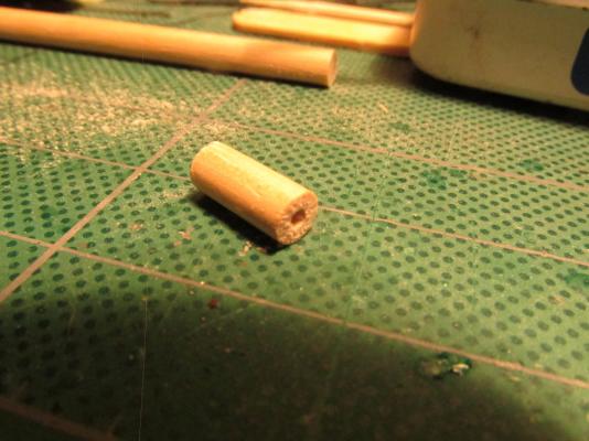
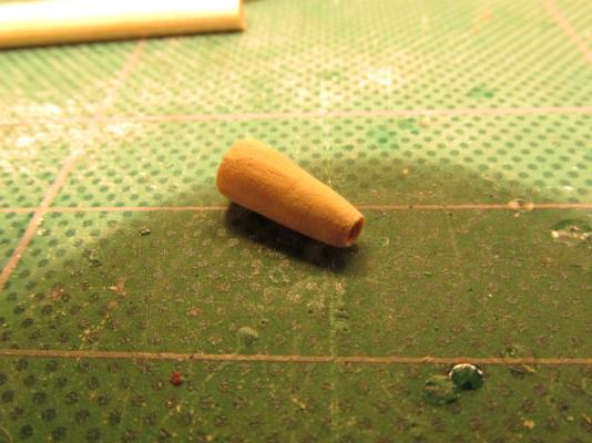
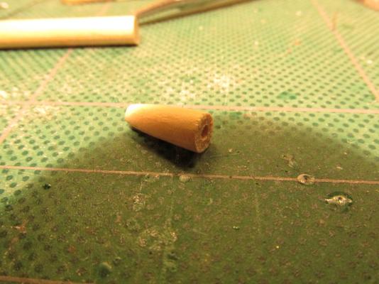
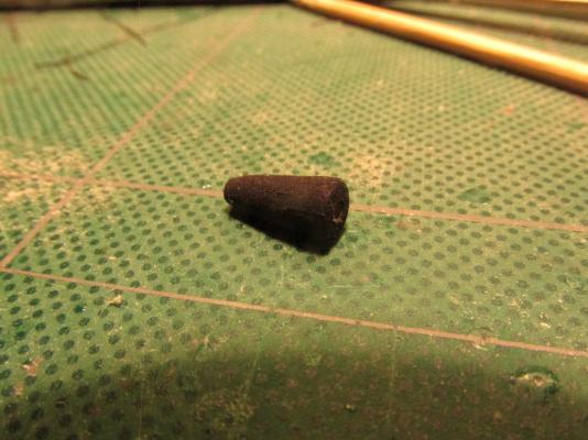
Main Stay Basically the Main Stay is made the same way as previous stays except the line is thicker (1.2mm). This required a larger mouse. My previous method would not work well at this dimension so this time used the cone method. A piece of dowel was first drilled with a hole that I could thread the line through. Then using hand files, the dowel was tapered at one end right down to the opening and painted flat black. The line itself was sized where it was to wrap around the mast as well as where it would rub against the foremast. The mouse was threaded on into position and sized into the line. During the sizing process, diluted PVC glue was applied over the mouse sizing to prevent it from slipping off.

- 974 replies
-
- 4
-
-
- rattlesnake
- mamoli
- (and 1 more)
-
Thanks all. I am presently away from the builder's bench for a couple days so it will be a couple of more days before the next installment (not that anyone would notice at my work pace).
-
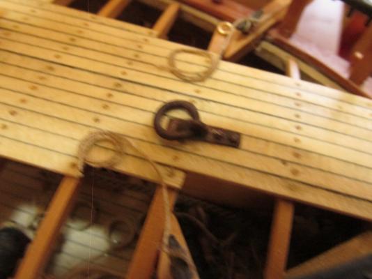
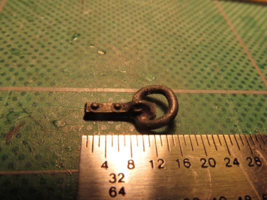
Now for the second learning experience; blackening the metal. The is the other thing I’ve never done. I bought the product Blacken-It. From what I read, you are supposed to dilute it. I diluted it 1:1 with water. Before I dropped in the completed assembly including the deck nails, it got a bath in the cleaning acid and a water rinse. I didn’t know what to expect; I was dealing with four different materials: copper, silver solder, brass, and whatever the nails were made of. The result was interesting. Everything got darker although I would say it was not black, more of a dark brown, a deep rust. This, on a ship, would not be surprising. The deck ring was installed in position according to plans.
- 974 replies
-
- 10
-
-
- rattlesnake
- mamoli
- (and 1 more)
-
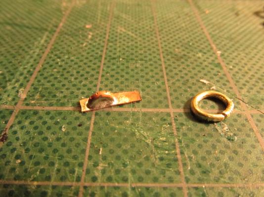
After drilling and filing out the opening, the full ring was added and two holes were drilled for some planking nails. These nails would become the rivets once installed to the model. The full ring was not soldered closed to enable it to be installed to the deck plate. The open ring seam would be hidden by the half ring.

- 974 replies
-
- 5
-
-
- rattlesnake
- mamoli
- (and 1 more)
-
I had previous purchased the following material for the soldering process: Cleaning acid Silver solder Flux Self-igniting Hand torch Following the instructions on the packages plus reviewing various build logs and other resources; I filled my head with enough facts, processes, techniques, do’s, and don’ts to make my head spin. Still, the only way to learn was to do it. I cleaned the pieces with the acid and rinsed them in water. I coated the area where I was going to solder the half ring with the flux I placed the half ring in position with a small piece of solder under the arch of the half ring Using the torch I heated the loos assembly carefully so as not to knock over the half ring from the pressure of the hot flowing gas Voila! As soon as the solder reached melting point it flowed immediately and locked the half ring into place. Unfortunately I used a bit too much solder because it completely filled in the opening.
- 974 replies
-
- 2
-
-
- rattlesnake
- mamoli
- (and 1 more)
-
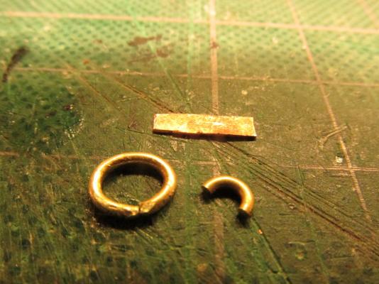
I measured the casting to determine that the ring and the half ring on the deck plate was 3/64” in thickness and I just happen to have some 3/64” brass rod. I had some copper plate and cut it to size to match the cast deck plate. If you look closely you will see two rivets on the deck plate as well. I curled the brass rod around a mandrel to form a ring the same size as on the casting for both the full ring and the plate half ring.
- 974 replies
-
- 2
-
-
- rattlesnake
- mamoli
- (and 1 more)
-
Now from the Learn Something New Department, in fact two things; first, Silver Soldering. The Mamoli kit provides a deck ring to anchor the Main Stay. It’s not so bad a casting but the ring is frozen to place. Here was a good opportunity to try some Silver Soldering, something I’ve never done.
- 974 replies
-
- 4
-
-
- rattlesnake
- mamoli
- (and 1 more)
-
I assume you are referring to the gun ports, I copied the elevation (side) view of Harold Hahn's plans and cut and trimmed it so I could lay it on framing to locate each gun port position. The gun ports follow the curved deck line and each are the same height off the deck. I made a mock up of a cannon and placed it on the deck to verify each port height. Don't forget to add the height of the deck planking! You can see how I did it on my log: Starting at Comment 25
- 481 replies
-
- 1
-
-
- rattlesnake
- model shipways
- (and 1 more)
-
Just because I'm ahead of you doesn't mean you can't ask questions. Ask away.
-
Just discovered your log today. Thank you for the kudos on the ship's boat. Everything you see on my log I'm experiencing for the first time so beware and read ahead, I make mistakes...lots of them. Hopefully, you won't fall into the same pitfalls I did. Good luck on your build, I look forward to follow it. Jonathan
- 481 replies
-
- 1
-
-
- rattlesnake
- model shipways
- (and 1 more)
-
I didn't actual buy a decal kit Per Se. I just bought a small pkg. of decal paper (for inkjet printer in my case) and a 3 oz spray can of Testors Decal Bonder. I first print the image on regular paper so I know where it's going to print and to check for scale I then taped a piece of decal paper onto the regular piece of printer paper over where the image printed and run it through the printer again. Then I spray the bonder over the printed decal paper and let it dry I trim off as much of the excess decal paper as possible Dunk the decal in water, apply to the model surface, and adjust the position When dry, I apply a coat of Micro Sol Settting Solution for Decals to soften the decal so that it tightly conforms to the surface and it conceals the decal edges Finally I apply a clear non-gloss (glossy as applicable) coating (usually polyurithane) to the complete surface, not just the decal, which seals it permanently
- 1,354 replies
-
- 3
-
-
- constitution
- model shipways
- (and 1 more)
-
If you are going to print the ship's name you might want to consider the method I used for my Rattlesnake using homemade decals: Namplate (Comment 337) Just remember, you cannot print white lettering! There is no white ink. You must print it as a negative with the background color matching the required color of the model area to receive the lettering. The area to receive the decal must be painted white, The printed white lettering will be transparent on the decal and the white area you paint will show through.
- 1,354 replies
-
- 3
-
-
- constitution
- model shipways
- (and 1 more)
-
JerseyCity - Just a thought, could a clear plastic straw been used instead of the bamboo skewer? You could have painted the inside of the straw to give the "lamps" a transparent lens look or would the wire detailing not work with the flimsy plastic?
- 396 replies
-
- 2
-
-
- Idea
- Bright Idea
- (and 1 more)
-
wq3296 - The practicum does two things, first for those people like me who never built one of these model before, it was a great help. Second, Bob Hunt's practicum is a kit bash. He deviates from the basic model to give more detail and panache. Jonathan
-
Now is a good time to review my log so you won't commit the same errors I did to the Captain quarters: Transom Modification - Somehow my transom came up shorten length which had repercussions further on in the build Captain's Bench The short answer is yes you can customize the bench. I didn't follow Bob's directions completely for the bench either due to previous errors and building technique. However, the visibility on the bench will be limited to just a few viewing angles so don't over do it. Jonathan