JSGerson
-
Posts
2,649 -
Joined
-
Last visited
Content Type
Profiles
Forums
Gallery
Events
Everything posted by JSGerson
-
 Beautifully done! Do you have any images of the step by step process on how you made those stars?
 -
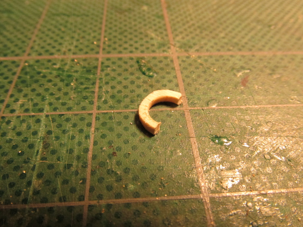
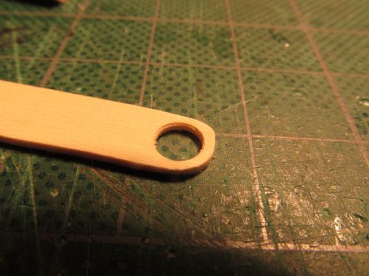
In addition to the cleats, the Mizzen mast had an additional feature which showed up on all the plans except Mamoli’s. This was a “rest support” (my term, don’t know what the nautical term is) for the boom. The only view I had was from the side so I just winged it. First I traced the mast onto a piece of 1/16” stock boxwood to get the inside diameter and then drew a larger concentric circle around that about 1/16” wider. With progressively large drills, the center was cut out and then the outside edge was filed to shape. With a fine saw the “ring” was cut in half and glued to the aft side of the mizzen mast at the height depicted in the drawings. Based on what I could see in the drawings I determined that there were five brackets under the half ring. I cut 5 1/16” cube pieces and with just a touch of CA glue, glued them into place. Once dried and set, with a fine diamond needle file, they were delicately filed to a triangular shape. A touch of Poly-Wipe and it was completed. Sounds simple but I screwed up a number of times with a number of re-dos, but all in all, it seems to work.


- 974 replies
-
- 6
-

-
- rattlesnake
- mamoli
- (and 1 more)
-
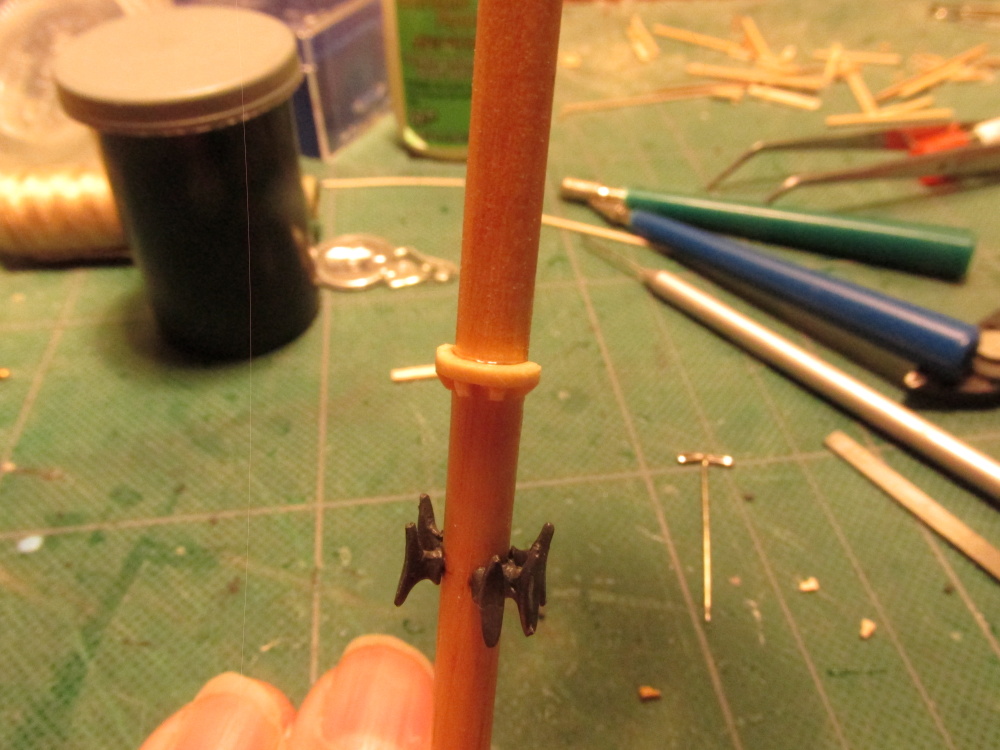
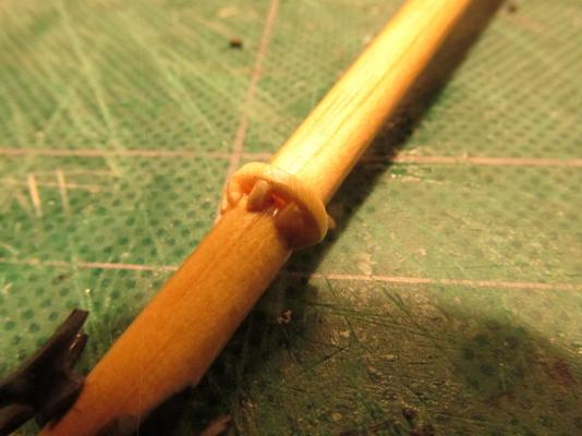
Back to the Masts Putting aside the bowsprit for a while (according to David Antscherl) I started to work on the Mizzen Mast. But before I could even start that, I wanted to make sure there was nothing left to put on the mast before it was locked into place. And lo and behold there was. Looking at views other than the construction views of the masts, I discovered there were cleats that had to be installed, six per mast. Even though this is a kit bash and not a scratch build, I felt a bit guilty using the kit’s cleats instead of making them myself because I've scratch built so much already; but use them I did.

- 974 replies
-
- 4
-
-
- rattlesnake
- mamoli
- (and 1 more)
-
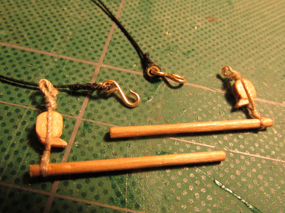
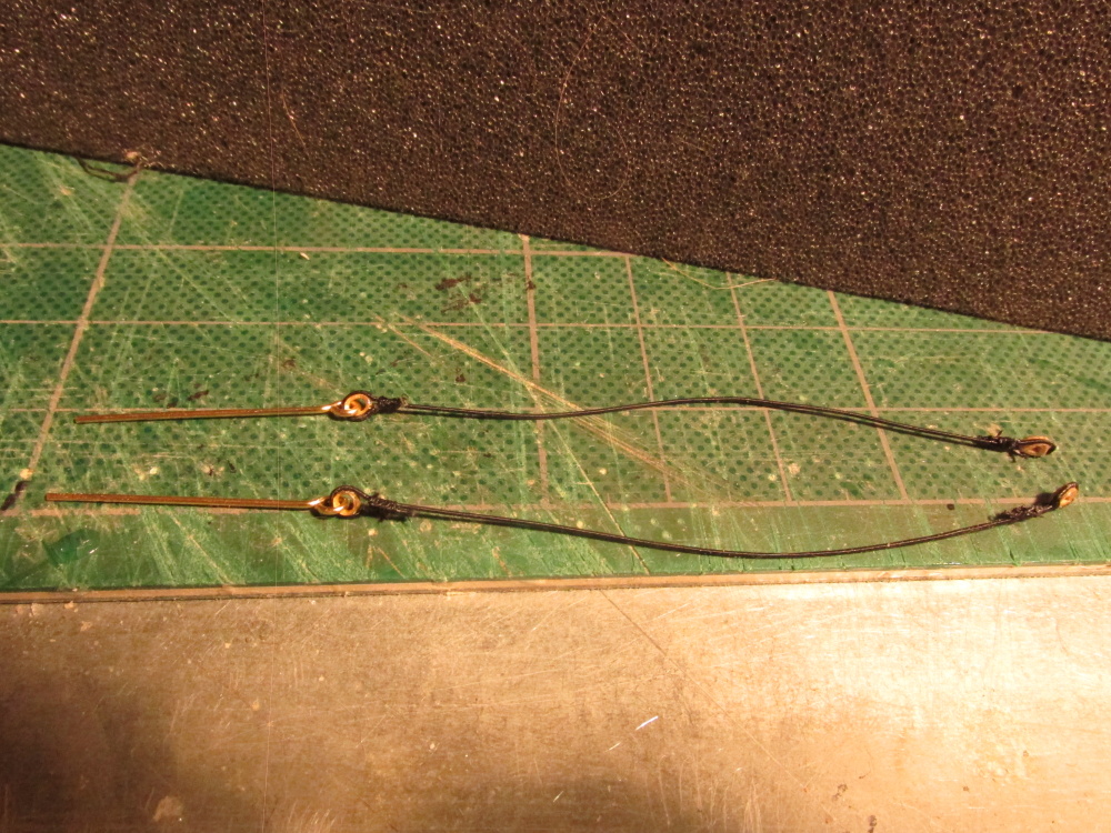
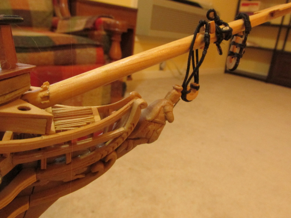
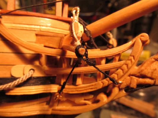
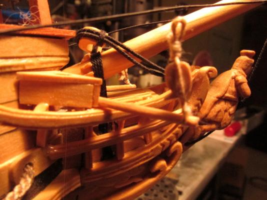
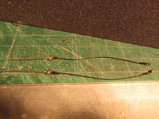
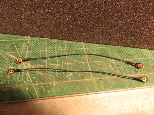
The aft lanyard was installed first. The eyebolt was first glued into place, and then the hook was attached. The loop on the other end now had to be made. I didn’t trust myself to make this loop beforehand and have it fit perfectly. Wrapping the seizing was a bit tricky while holding everything in place but I got it done. The fore lanyards were added in the same manner: one end premade and the other made on the model.
- 974 replies
-
- 5
-
-
- rattlesnake
- mamoli
- (and 1 more)
-
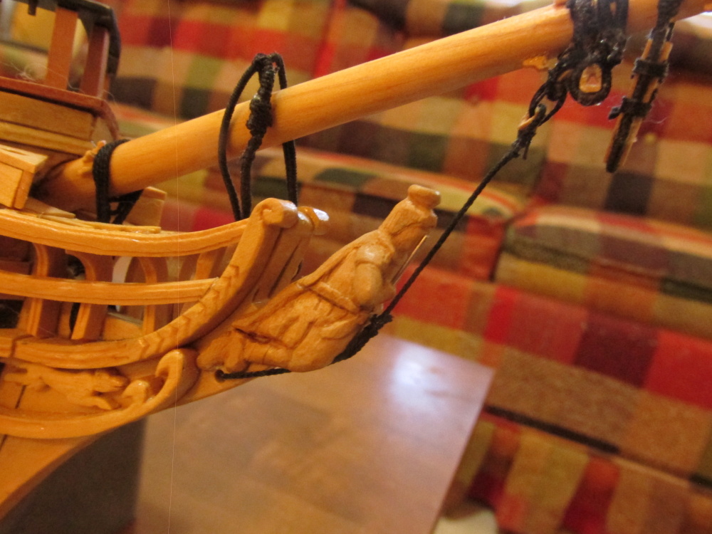
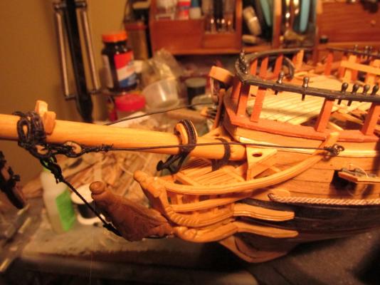
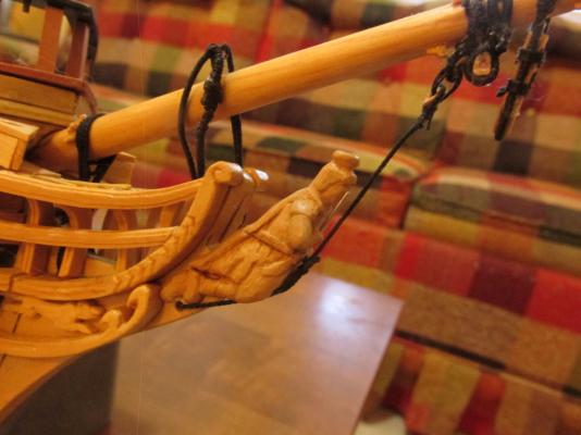
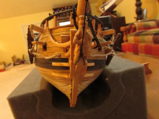
With most all the parts made, the boomkins were installed. My model was initially built using Pasi Ahopelto’s model as a guide, specifically for the seats of ease. At the time, I had not seen or at least not recognized what they were on other models, so mine as with Pasi are fairly unique. As a result my boomkins fit snugly against the seats as opposed to looking free standing on other models.
- 974 replies
-
- 4
-
-
- rattlesnake
- mamoli
- (and 1 more)
-
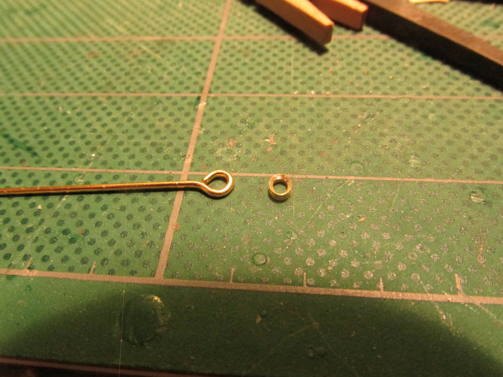
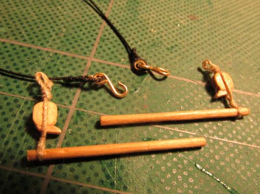
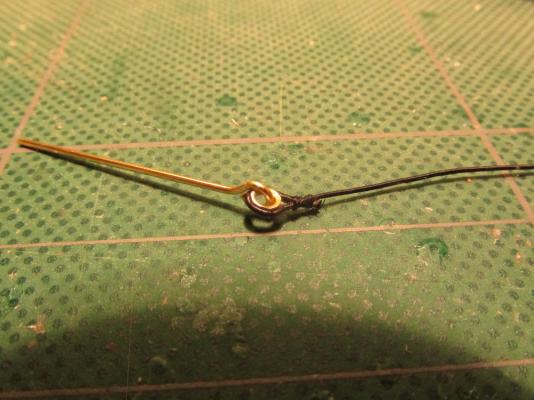
In addition to the Fore Tack Blocks, there were two boomkin shrouds per boomkin. Again although not shown in either kit plans, Mr. Antscherl states that the aft shroud is attached to ringbolts by means of a lanyard by thimbles and hooks. The fore ones attached directly to the ringbolts. The thimbles were made as before, cut from stock tubing; the hooks were bent to shape from leftover brass eyebolt shafts cut off from previous constructions. For the aft lanyard, the thimble and loop were on one end and a simple loop on the other. The fore lanyards would have simple loops on both ends.
- 974 replies
-
- 6
-
-
- rattlesnake
- mamoli
- (and 1 more)
-
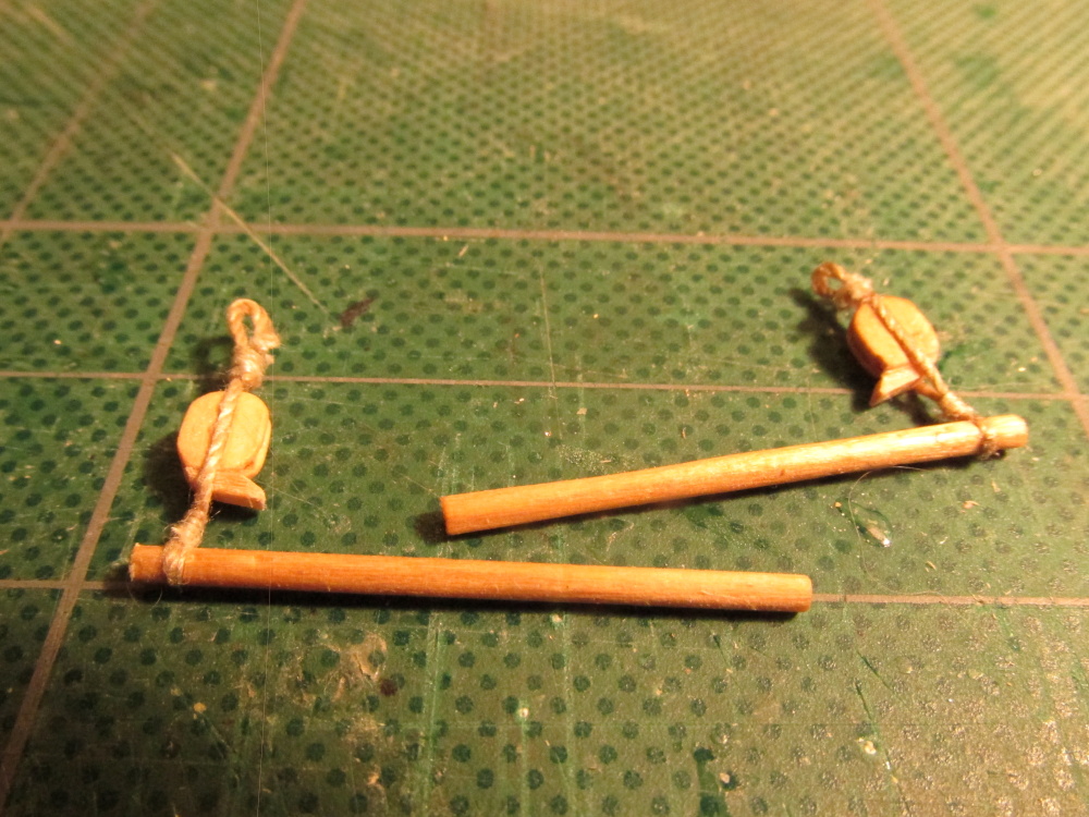
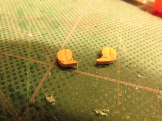
The shoulder blocks were stropped with a loop on both ends. The bottom loop was fitted onto boomkin with the shoulder pointed inward towards the bow.

- 974 replies
-
- 4
-
-
- rattlesnake
- mamoli
- (and 1 more)
-
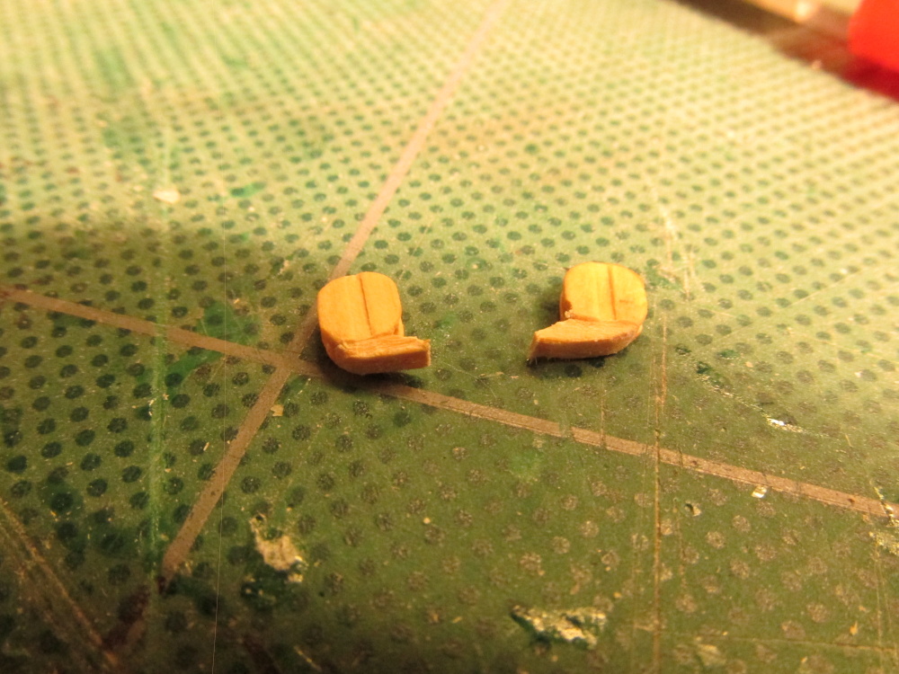
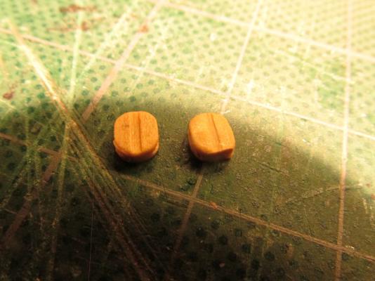
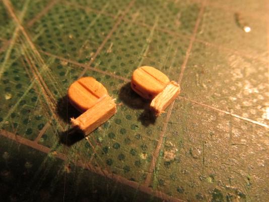
The first items to be attached to the boomkin were the Fore Tack Blocks. According to Antscherl (who quotes Steel) these were 14” long shoulder blocks which carried a 3½” circumference rope. This works out to a 5 mm block and a .4 mm f line. The problem is that Syren Ship Model Company, whose blocks I’m using, does not make shoulder blocks. Luckily David Antscherl explained how to make them. First the blocks were flattened a bit on the bottom. A piece of stock boxwood, the same thickness as the block and whose length was a bit longer than the block was wide, was glued to the flatten bottom of the block such that it extended a little bit beyond the block on one side only. Once the glue had dried and set, it was carved to the proper shape with a hand file.
- 974 replies
-
- 2
-
-
- rattlesnake
- mamoli
- (and 1 more)
-
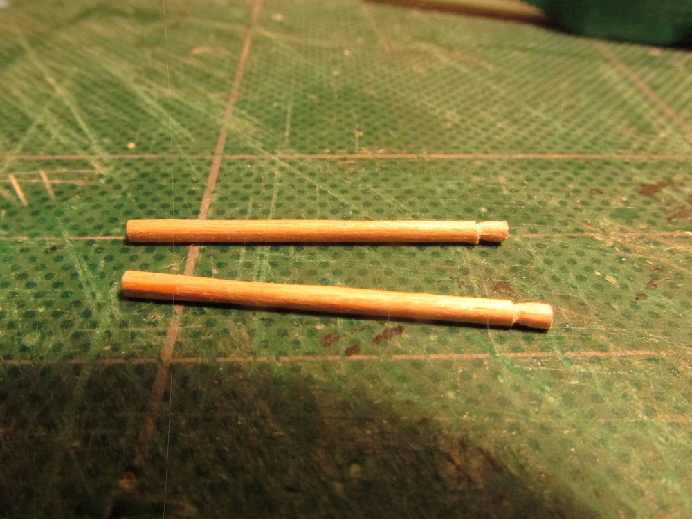
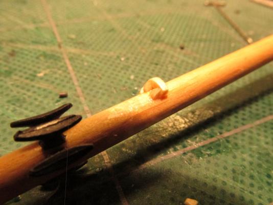
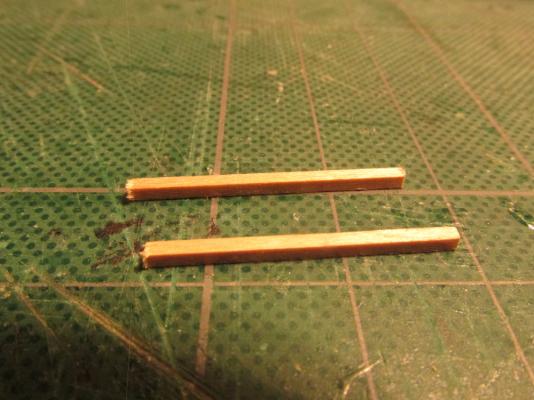
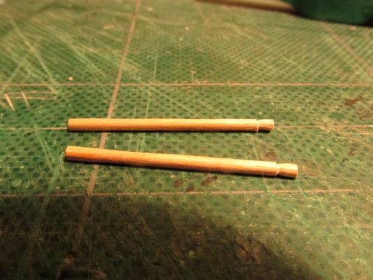
Boomkins Continued to follow David Antscherl’s FFS, so the Boomkins were next in line for construction. Although the Mamoli plans showed the boomkins as square in cross section, every other resource showed them to be round including Mr. Hunt’s practicum. The boomkins were cut from 1/16” square stock boxwood and rounded. At one end of each boomkin, it was reverse tapered. That is, just before the end of the boom, the diameter was immediately reduced in size then tapered back to the fully diameter at the end of the boom. This would allow the lines to catch hold.
- 974 replies
-
- 2
-
-
- rattlesnake
- mamoli
- (and 1 more)
-
If you didn't do it, you would never be happy with the model. Biting the bullet can be bitter but the end results are much sweeter.
- 335 replies
-
- 2
-
-
- Constitution
- Mamoli
- (and 3 more)
-
As with anything you touch, it is gorgeous creation. Just perchance, did you happen to create a build log of the Constitution? I couldn't find one by you on this site. If it's on another site, I would love to see it. The Constitution is my next project whenever I finally finish the Rattlesnake.
-
Thanks for the quick reply. I wish I could use those items but I think they are too big for small lines I'm working on now. The hearts I've made so far are about 3 mm, and the thimbles about 2.5 mm brass. My main tools are a fine tooth saw, a hand drill, and a bunch of needle files. Combine that with tenacity and patience and you can make those simple parts.
- 974 replies
-
- 2
-
-
- rattlesnake
- mamoli
- (and 1 more)
-
Scott, out of curiosity where did you order the hearts from? So far the ones that I've used, I've made myself which I admit are not perfect. Syren Model Ship Co (whose stuff I love) has hearts as small as 5.5 mm but I think that is still too large for where I just used mine.

-
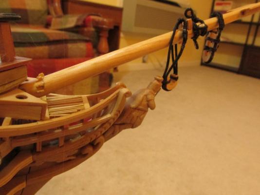
The bow end of the shrouds were attached first then the hearts were lashed together to those on the bowsprit.
- 974 replies
-
- 3
-
-
- rattlesnake
- mamoli
- (and 1 more)
-
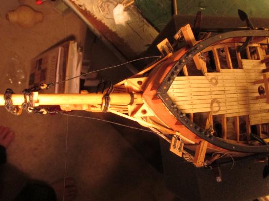
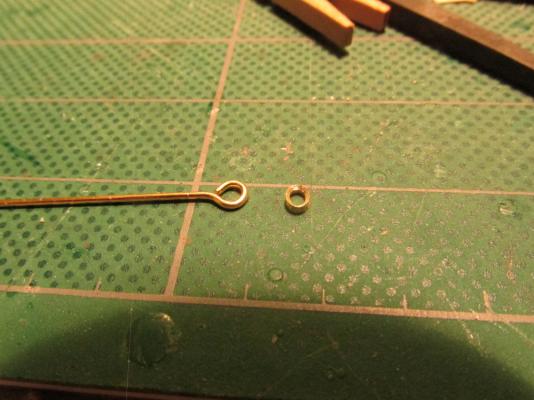
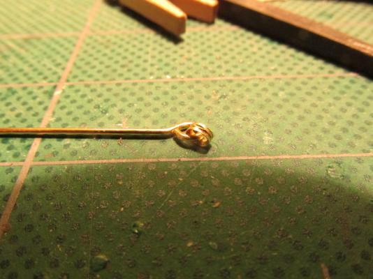
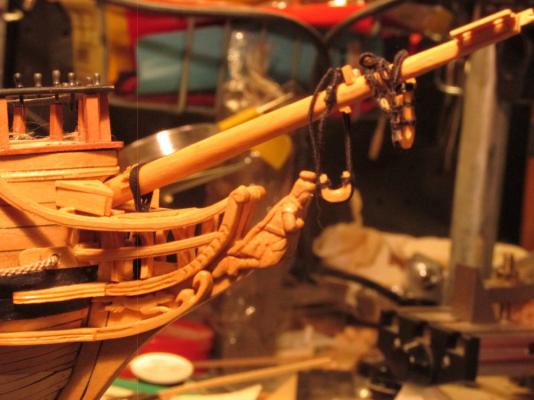
Bowsprit Shrouds The bowsprit shrouds are fully served with one end attached to bow eye rings with an eye loop splice. The other end is looped spliced with a heart. The heart is lashed to the hearts installed earlier at the sides of the bowsprit. Although not shown on the plans, I elected to follow David Antscherl’s FFS and added a thimble into the bow eye splices. A Piece of brass tubing was first reamed to create a conical edge to the hole on one side which was fairly easy using a Dremmel drill with a fine burr on it. The piece was then cut off the tube stock. Reaming the other side was a bit more difficult due to its tiny size. For that, I used a button reamer hand tool. With a fine file a groove was filed into the edge of the ring to hold the line in place. Since the edge was going to be covered by the line, it didn’t have to look good, just be functional. BTY: The burrs I used in the Dremmel I got from my Dentist. I asked him what he did with his drill bits/burrs when they wear out and he told me after he uses them once, he tosses them. After I told what I wanted them for model making, he collected a week’s worth for me and now I’ve got a “lifetime” worth! These are diamond coated burrs in various shapes and sizes and looked brand new.
- 974 replies
-
- 4
-
-
- rattlesnake
- mamoli
- (and 1 more)
-
Bobstay The Bobstay is a fully served line with one end passing through the stem and fastened to itself in front of the figurehead as a long loop splice. The other end is looped spliced with a heart. The heart is lashed to the heart installed earlier under the bowsprit.
- 974 replies
-
- 2
-
-
- rattlesnake
- mamoli
- (and 1 more)
-
I agree, a diagram would be very useful. How does this work with double or triple sheave blocks?
-
There are two sources for the belay pins I know about - Visit the ship in Boston - Anatomy of the Ship, The 44-Gun Frigate USS Constitution, "Old Ironsides" by Karl Heinz Marquardt I think getting the book would be a bit easier 8-)
-
Nice paint job!
-
Thanks for the kind comments Martin. The Seat of Ease is based on Pasi Ahopelto's model (before the site crashed). He has since resumed his log but he has not re-posted all that was lost. At the time I was constructing it, I had not seen (or at least recognized) one on other models so I followed him. Now I see that his design appears to be a bit unique in the triangle shape. Still, it works for me.
- 974 replies
-
- 1
-
-
- rattlesnake
- mamoli
- (and 1 more)
-
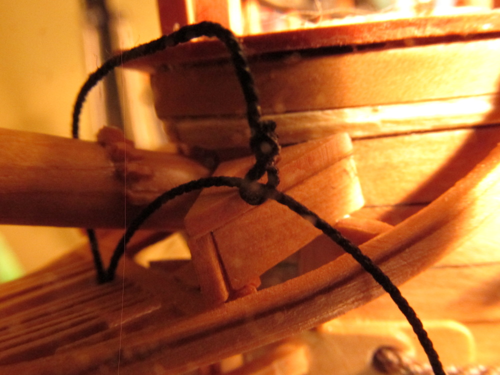
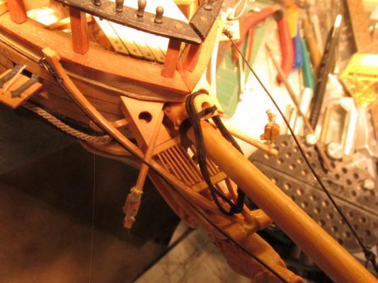
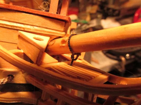
Then it was wrapped around the vertical lines horizontally half way down under the grating. The horizontal turns were supposed to equal the number of vertical turns but elected to do only two. The space was quite cramped and even with a light aimed directly in there, it was hard to tell there was any wrapping at all.

- 974 replies
-
- 4
-
-
- rattlesnake
- mamoli
- (and 1 more)
-
Using .45mm Syren Ship Model Company black miniature rope, the gammoning, was started with an eye splice and then threaded through the grating, through the gammoning hole in the stem, and back up top four times.

- 974 replies
-
- 2
-
-
- rattlesnake
- mamoli
- (and 1 more)
-
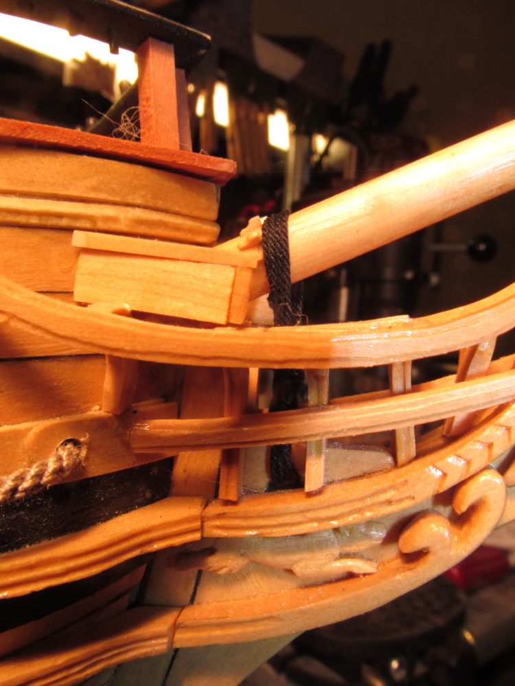
Installing the Bowsprit I had gotten as far as I could with the bowsprit and its constituent components; it was time to install bowsprit. I used epoxy glue at the base of the bowsprit and slid it into place.
- 974 replies
-
- 1
-
-
- rattlesnake
- mamoli
- (and 1 more)
-
My skills? I have never done this stuff before! I'm learning as I am going which is why I'm moving as slow as I am. I just taking one step at a time, trying to make as few errors and do-overs as I can, but no matter how I try, I make a bunch of them...I just don't post most of them 8-)
- 974 replies
-
- 2
-
-
- rattlesnake
- mamoli
- (and 1 more)
-
Sorry for the delay in responding but I was at the NRG Conference in St. Louis last week and just got back today (19 Oct 14). Trying to respond to email on an iphone is hard on the eyes. I don't know how those young kids do it. So onto your question. I had a great time by the way. I can't take credit for the method I showed. I am following Blue Ensign as he builds the HMS Pegasus (starting at comment 696 for the foot ropes) who by the way credits Gil Middleton for the pseudo (my term) splice. See, we all help each other. See if Blue Ensign's more detailed descriptions help. If you still have questions, please feel free to ask me again.
- 974 replies
-
- 1
-
-
- rattlesnake
- mamoli
- (and 1 more)