JSGerson
-
Posts
2,646 -
Joined
-
Last visited
Content Type
Profiles
Forums
Gallery
Events
Everything posted by JSGerson
-
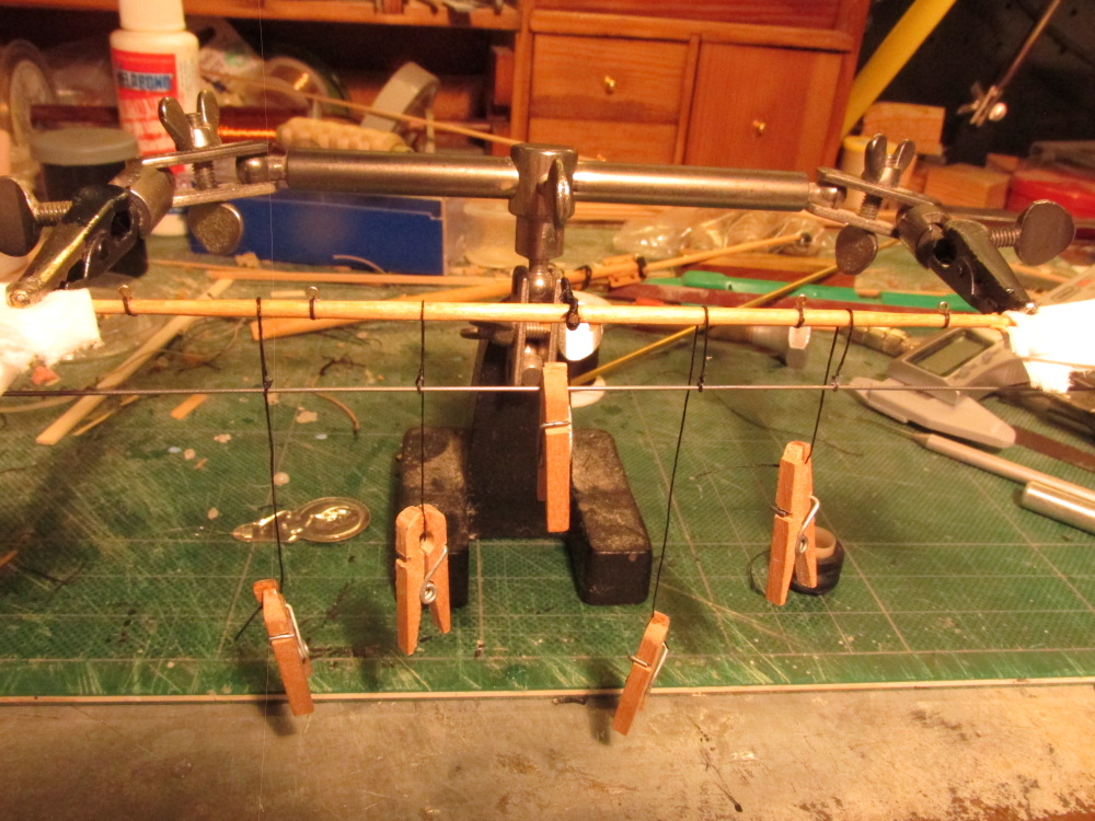
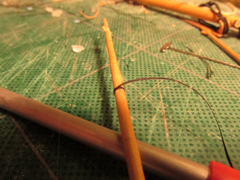
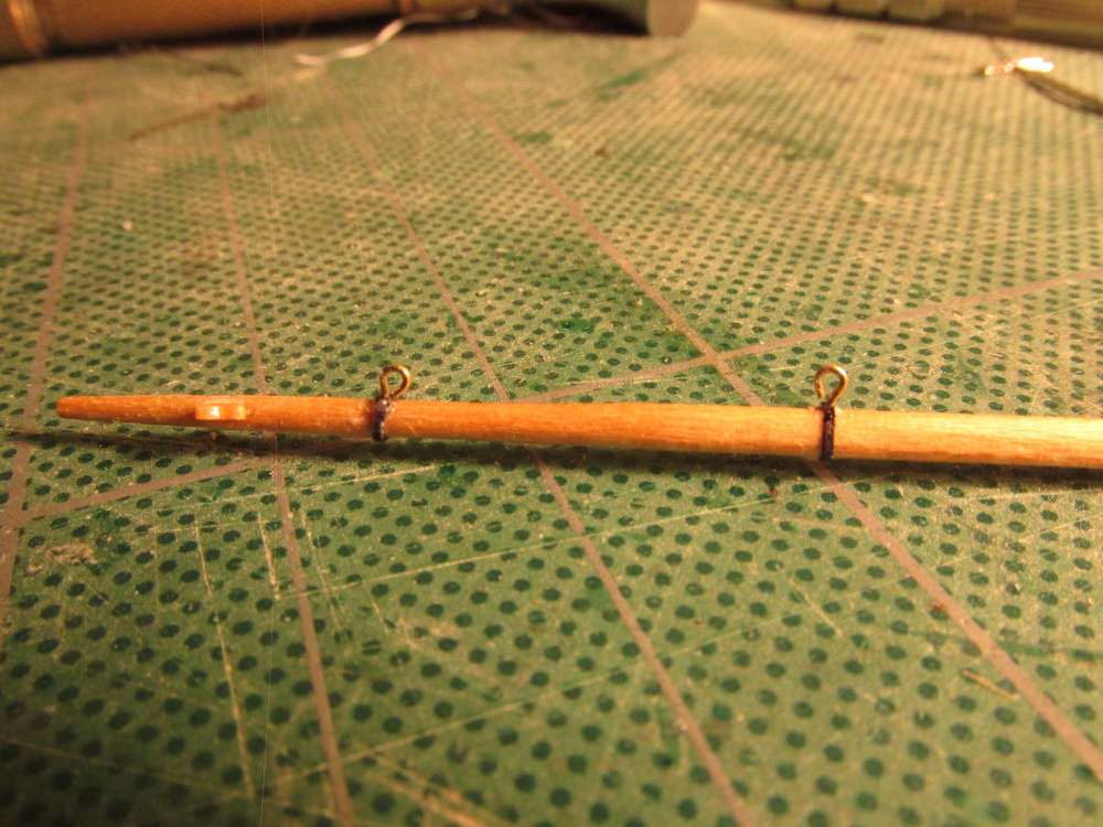
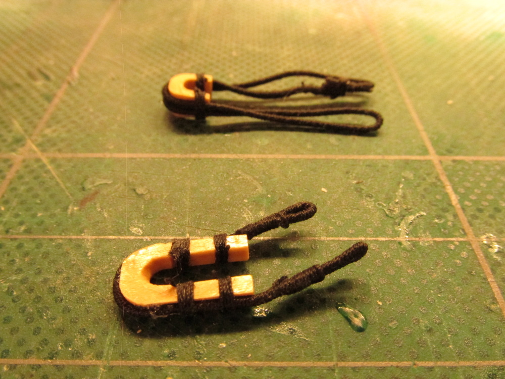
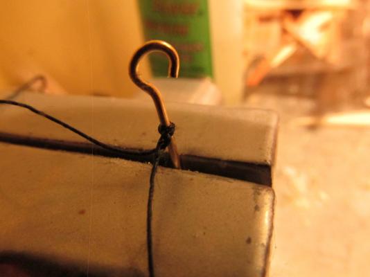
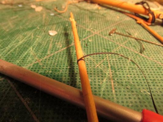
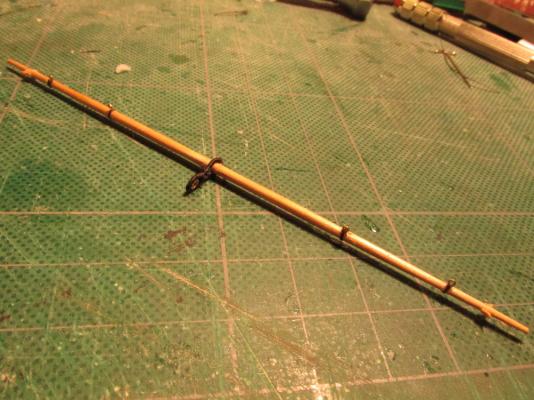
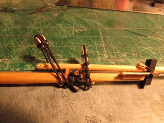
 Once I had four stirrups made and wrapped around the spritsail yard in the proper position, I inserted a music wire which had the same diameter as the eyelet through the stirrup loops and made sure everything was level and even. I used a clothes pin to add some weight to the wire to keep the stirrups taut. The wrappings around the yard were then glued into place and the vertical lines were “painted” with diluted PVA glue to stiffen them up.
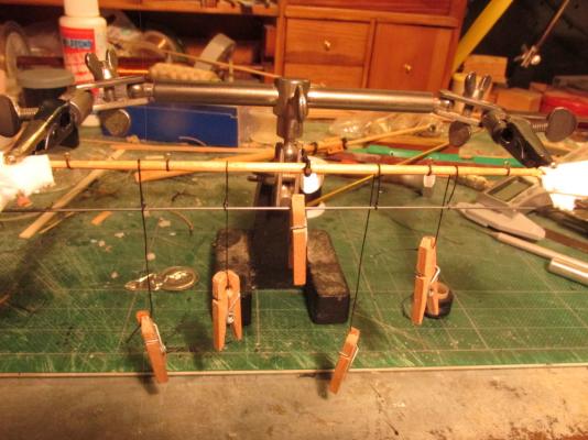
- 974 replies
-
- 5
-

-
- rattlesnake
- mamoli
- (and 1 more)
-
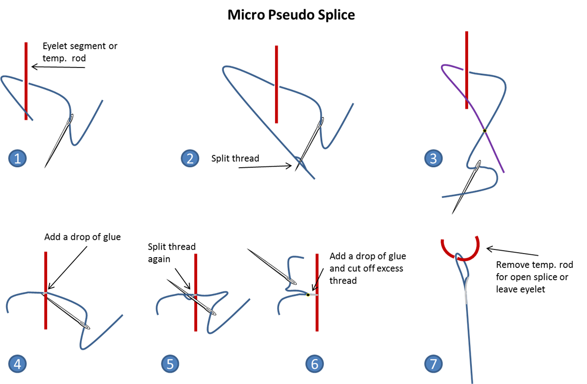
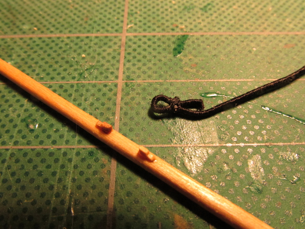
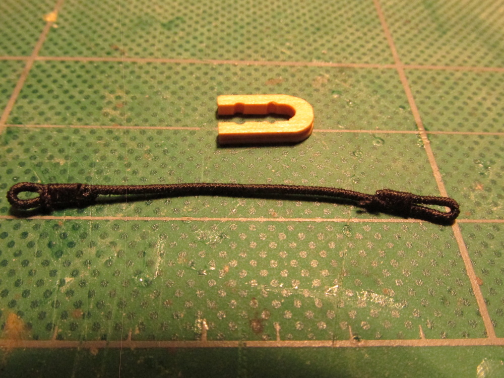
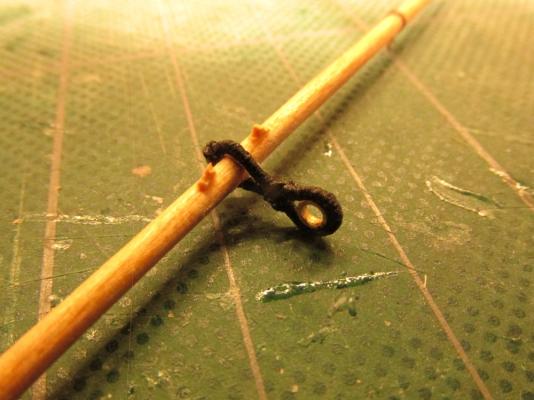
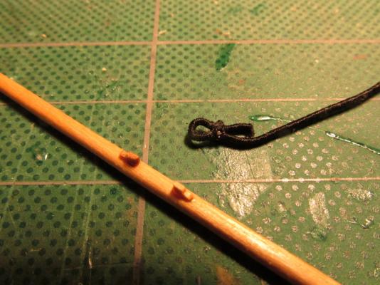
The methods work well to add a loop splice to an eyelet or in this case just an open loop. To create the open loop, I used the long end wire of an eyelet. When completed, the loop was slid off leaving an open loop.
- 974 replies
-
- 2
-
-
- rattlesnake
- mamoli
- (and 1 more)
-
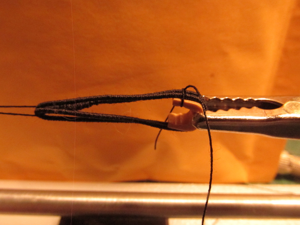
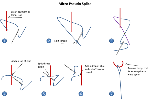
After doing a bit of research (thank you Blue Ensign and Gil Middleton) as to how to make the stirrups and foot ropes, I came across (for lack of a better term) the Micro Pseudo Splice. I looked at a number of builders’ methods and this seems to be the best (to me at least). Because of the small scale, making a real splice is neigh impossible and making it look to scale. This method is real simple (because even I could do it) and the results are clean. I drew up the method as shown below.
- 974 replies
-
- 5
-
-
- rattlesnake
- mamoli
- (and 1 more)
-
I've discovered another method for applying the "caulking" paper to the planks. Start with a sheet of wood the thickness of the required planks width and veneer a sheet of paper (your choice of color) on top of it. Then slice planks to the width of the thickness of the desired plank with a Byrnes Saw (or similar). When the strips of wood are rotated 90 degrees, the paper/caulking will now on the vertical edge. No more applying paper to individual pieces of wood; dozens of planks can be made at a time.
-
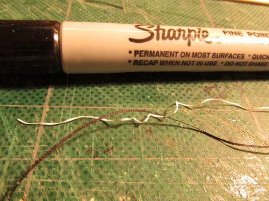
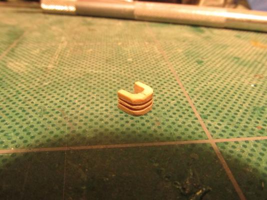
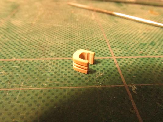
The spritsail yard has rings on it for the guy pendants. Actually they are thimbles on a metal band that wraps around the yard. To simulate this, the metal band is simple thin strip of paper cut from some plain copier paper and colored black with a Sharpie pen. The eyelets that came with the Mamoli kit are 3 mm f which I thought were way out of scale so I used ones which were about 1.5 mm to make the thimbles.

- 974 replies
-
- 3
-
-
- rattlesnake
- mamoli
- (and 1 more)
-
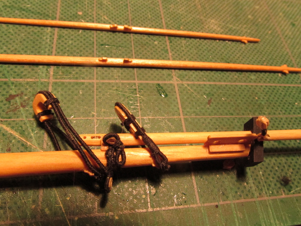
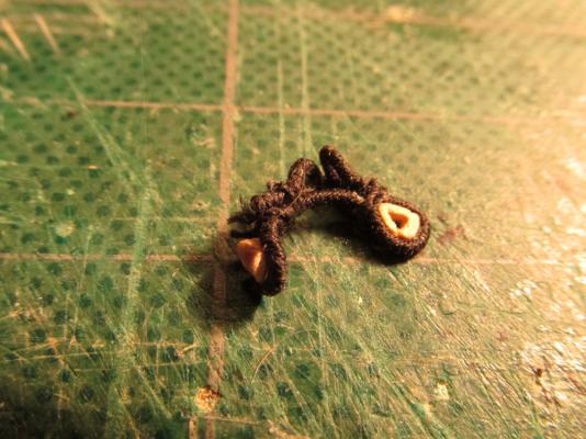
A piece of the tubing was then cut off from the stock material about the same thickness as the seized line. Using tools I bought for making jewelry, I used a bead reamer to flare out the inside hole of the brass “donut” on each side and filed a groove around the outside edge to hold the line in place. Then it was just a matter of placing it inside the line loop. It was at this point I realized I now had a problem as how was I going to get it on the yard. This component should have been made and installed before the cleats were glued into place. Then the line would have been formed into a circle with a pseudo splice. The circle would have been cinched and seized to form a figure 8 with a smaller loop on top for the thimble. The larger loop would then slide onto the yard. Of course the dimensions of the initial circle would have had to been dead on. But I didn’t do it that way. Instead I had to glue in increments first to put it into position and then to wrap the two open ends around the back to cut them to size so that they would butt up to each other. Then I glued them down. Maybe the way I did do it was easier, I don’t know.
- 974 replies
-
- 4
-
-
- rattlesnake
- mamoli
- (and 1 more)
-
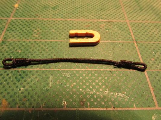
The bowsprit yard has a thimble spliced loop sling (technical term right?) Actually depending on what source you are looking at, there is a thimble or not. I chose to use one. Again, the line was served and then one end of the served line was wrapped around a stock 3/32” brass tube to from the loop and seizing to the right size.
- 974 replies
-
- 2
-
-
- rattlesnake
- mamoli
- (and 1 more)
-
I am curious as to how you added the namesake to the stern. It looks like you used my method or a modification of it. Make a plaque Paint it Apply a homemade decal (in my case) or rub on letters (transfers) Seal the plaque Place the plaque on the model
-
Beautiful as always. How do you maintain the proper angle so that you end up with a nice octagon cross section? I mark a cross on the ends so I know how much to rotate the wood, but mine always seem to come out lop sided and then I have adjust with sanding.
-
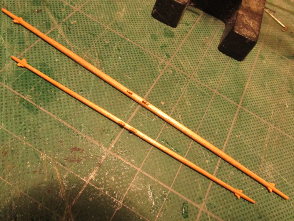
Knowing that the bowsprit and the jib boom had yards slung from them and therefore need slings made, the spritsail yard and the spritsail topsail yard were constructed. Again this is following the philosophy of making everything I can off-ship before stuff is nailed down, as it were.


- 974 replies
-
- 8
-
-
- rattlesnake
- mamoli
- (and 1 more)
-
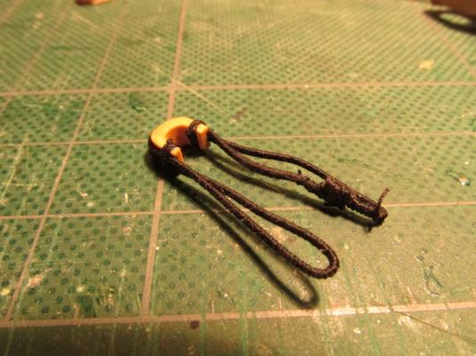
Something wasn’t right – it was too cluttered. I didn’t like the two hearts which were on either side of the bowsprit. I had made them separately. Looking closely at the drawings and books again, it appears the hearts were both on one same sling. The hearts were removed and a new double heart sling was fashioned.
- 974 replies
-
- 2
-
-
- rattlesnake
- mamoli
- (and 1 more)
-
It was again time to dry fit all the components so far. But before I did that I added some eyelets, made holes for additional future eyelets and added blocks to the installed eyelets on the bowsprit cap. Then I assembled them all together.
- 974 replies
-
- 5
-
-
- rattlesnake
- mamoli
- (and 1 more)
-
There are a number of well made, sturdy 16" scroll saws out there. That's what I'd get, will get in time. It's an invaluable must have tool.
-
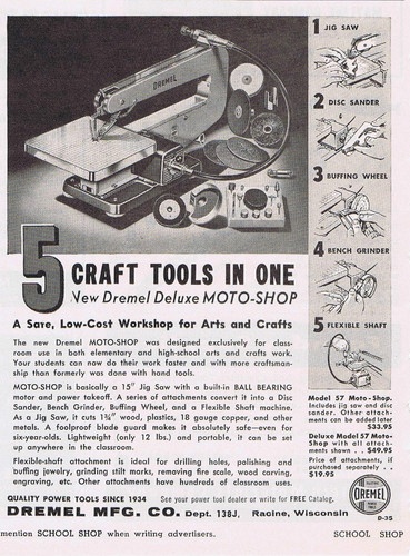
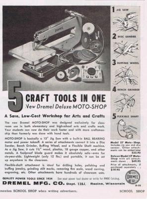
Ken - Funny you should ask about the scroll saw. I have a Dremel Deluxe Moto-Shop 15" scroll saw, with attachments for a flex shaft, and disk sander. I purchased it in the late 70s. It still works as good as the day I got it but that is not saying too much. The problem is that it vibrates like crazy. The disk sander doesn't hold the sanding disks very flat (uses a wide center machine screw), and the flex shaft is not all that smooth in its operation. It's a neat design and should have been perfect for a hobbyist, but it is not a true precision machine. It is what I have so I make do. One of these days I would like to replace it and oh yeah get a mini lathe/milling machine as well when I'm feeling flush...very flush.
-
They are the same scale, 1:64. The reason I chose the Mamoli kit was that I planned to (am still am) following Robert Hunt's Practicum (some what now) which he based on the Mamoli kit. He claimed you could also use the MS kit with some minor modifications. I started this project in late 2009, so its been 5 years and as you can see, I still have as ways to go. Back then, I knew nothing and I mean NOTHING about building this type of model which was the reason I was following the Practicum. At that time, I didn't even know Model Expo existed! So I went to ebay and found the kit, bid, and won the auction for about $250 (if I remember right). I didn't even comparison shop. I don't know how the two compare quality wise since I have never seen the Model Shipways version. Due to comments on my log and others, I found that a lot of builders purchased just the Model Shipways plans which give you a second way of looking at things. Some details are explained different or better than the other. So I ended up with three set of plans, the two kits plus Harold Hahn's plans which the Practicum uses to supplement the Mamoli kit plans. A lot of the hardware the Mamoli kit provided, I didn't use: I got a replacement wood supply, I scratch built many of the items (cannon carriages, the bittle, lower deck partitions, stern carvings, etc. I don't know what the MS kit provided or didn't. The biggest thing I didn't like about the Mamoli kit was that all of the instructions were printed on the 11 sheets of plans in fine hard to read print. Since I didn't follow those instructions for the most part, it made no difference. If I had to, I would have transcribed them on a word processor and printed them out. Both kits provide certain how-to details and ignore others. The MS kit provides four sheets of plans and booklet of instructions (which you can download). I couldn't of done it without the Practicum. Confused yet? Jon
-
Ken, as far as I know, there is only one model of the Byrnes Table Saw. There are however two different voltages, I have the 120V for use in the USA as opposed to the 230V. Over the years I have purchased all of the bells and whistles for the saw (different blades, both micrometer stops, fence extensions, and even the tilt table, etc.). I haven't used the tilt table yet for a real project. I have also purchased the draw plate which is invaluable for making tree nails and the dimension sander. I would have purchased the disc sander but I already had one. The Byrnes rope walk is another matter. Until I play with my Model Expo ropewalk to make quality rope and determine it is worth the effort as opposed to buying it from Syren Ship Model Co. which makes top notch rope, that fantastic machine of his is on hold. I would have to have a need from a tremenous amount of miniature rope to justify the cost. As you may surmise, I am a tremendous fan of Jim Brynes and his company. As far as the other subject, the crow's feet, I look forward to rigging that. I am told that it really is not that difficult to make. That's still down the road a bit. I have yet to install any mast, and that rigging is on the third level. Jon
-
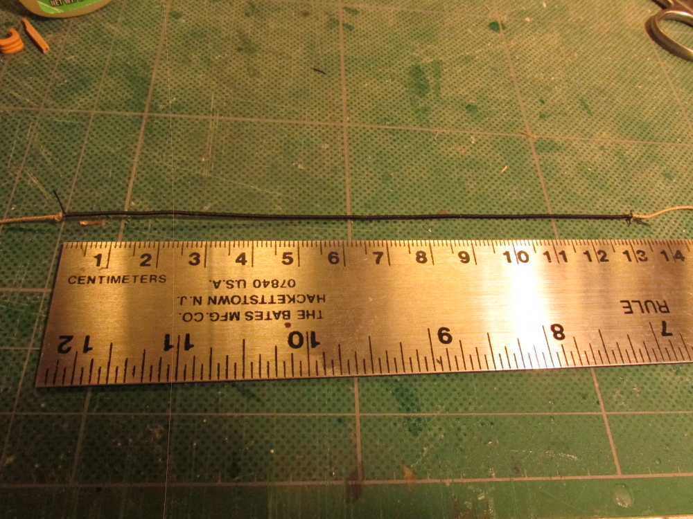
The fore preventer wasn’t measured as it was fitted to the collar. A sufficient length of 0.63mm served line was created. A loop was made at one end and then wrapped around the collar to determine where the second end loop would be constructed and therefore determine the required line length. Once the second end loop was made, the line was again wrapped around the collar and lashed at four points. The double lashing was based on Rigging Period Ship Models by Lennarth Petersson.

- 974 replies
-
- 7
-
-
- rattlesnake
- mamoli
- (and 1 more)
-
The loop was then squeezed together and formed around the collar with the lines in the collar grooves. The line was then lashed to collar at the inner indentations made for that purpose.

- 974 replies
-
- 5
-
-
- rattlesnake
- mamoli
- (and 1 more)
-
Per FFM, the forestay collar strapping was made from 0.63mm served line 128mm leaving unserved line at the ends. The ends were cut diagonally (as best I could) and glued together. I found I had to be generous with CA glue as the ends would come apart just by looking at them. The joint was then seized manually without the use of the seizing machine which can’t work on loops.


- 974 replies
-
- 2
-
-
- rattlesnake
- mamoli
- (and 1 more)
-
You can see from Hahn’s plan how the collars fit into place.
- 974 replies
-
- 2
-
-
- rattlesnake
- mamoli
- (and 1 more)
-
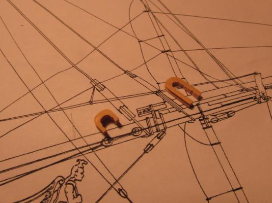
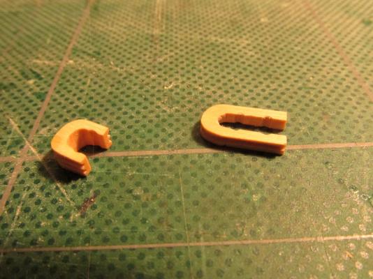
A second collar had to be constructed similar to the first for the fore preventer stay. This is the line the crow’s feet attach to and therefore not shown on the Mamoli or Model Shipways plans. Unfortunately this collar is different than what is shown in Antscherl’s book – it is much longer and appears narrower in Hahn’s plans. I took my best shot and winged it. Again the collar had to be the same width as before but almost twice as long. In this case I followed Hahn’s plan and made it with one side groove. It was constructed about ½” long from ¼” x 5/64”

- 974 replies
-
- 1
-
-
- rattlesnake
- mamoli
- (and 1 more)
-
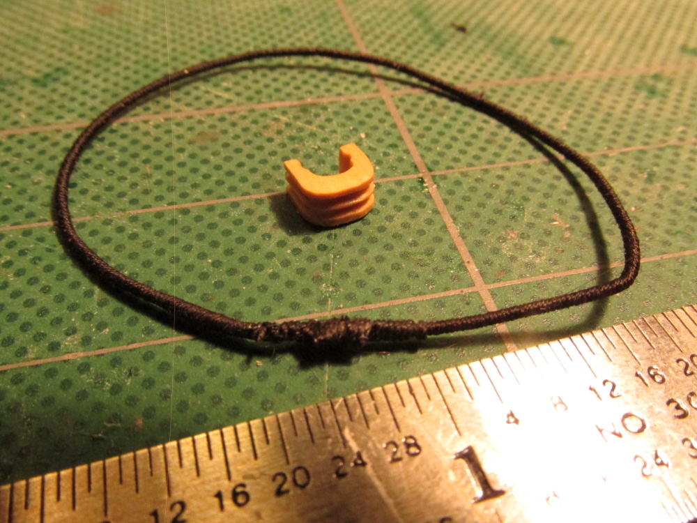
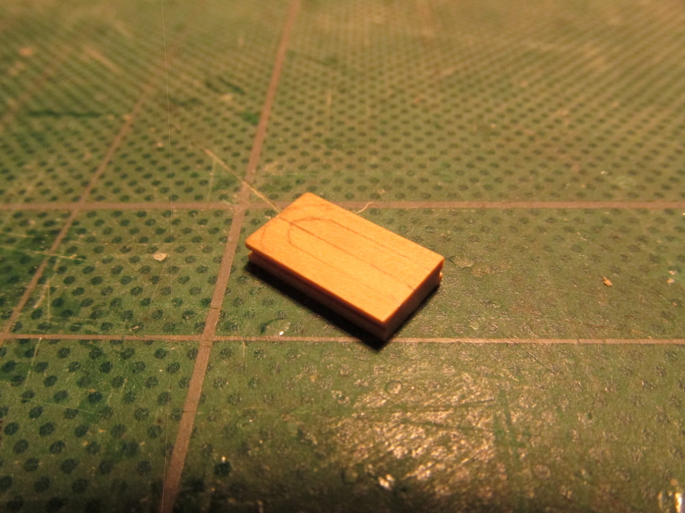
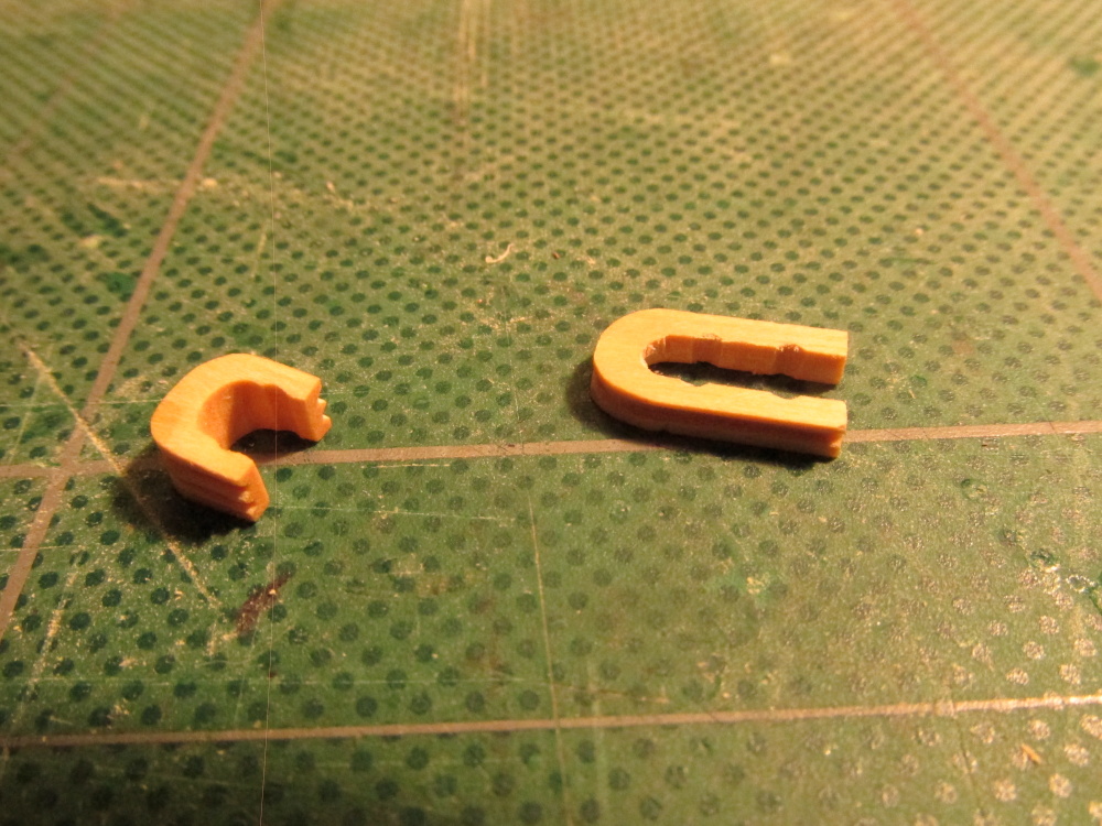
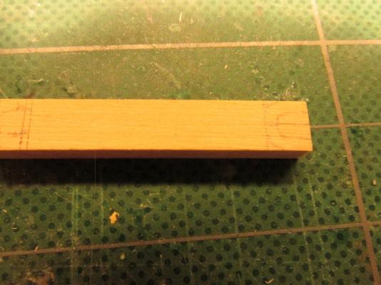
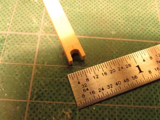
At this point a choice had to be made. Both the Mamoli and ModelShip plans were in agreement with each other but not with Harold Hahn’s plan. Mr. Hahn showed crow’s feet rigging and since I had decided early on to follow the Hahn plans when possible, the crow’s feet were in which affect some of the rigging scheme. Some other details like whether to use deadeyes or hearts on the bowsprit also came into play. From my readings and looking at the various models, it was apparent that there really wasn’t a rigid standard rigging scheme. A lot of the details were at the discretion of the captain and those could change during the course of one cruise. Since I’m the captain of this particular ship I can’t be wrong…mostly…well maybe. I made two more hearts similar to the bobstay to wrap around the bowsprit for the two bowsprit shrouds The forestay has an open heart. Following the guidance of David Antscherl’s The Fully Framed Model, Rigging a Sixth Rate Sloop of 1767 – 1780, Volume IV [FFM], the open heart or the forestay collar as Antscherl calls it. “This is a 13” open heart with a 5” four-strand cabled collar that is doubled,” requires two grooves along the side which will be apparent below. This does not follow Hahn’s plans or at least I think it doesn’t because the only view is from the side and shows one groove. But as I stated before, I’m the captain. The idea of the heart is to allow the jib boom to slide between the forestay lines. Based on that, the 3/16” long heart was made from a piece of ¼” x 1/8” boxwood. The grooves were initially cut with the Byrnes saw and the filed to a semi-circular cross-section.
- 974 replies
-
- 2
-
-
- rattlesnake
- mamoli
- (and 1 more)
-
Glad to have you posting again. You and I are at about the same point in our Rattlesnake builds abet mine is 1:64 scale. Now I'll have you to lead the way once more. I await with high anticipation!
-
If you can't get anymore cannons of the type you want/need, you can always close the gun ports under the fore and aft decks to show what the ship looks like with them closed. Because your decks will be completed (I assume, unlike mine) the viewer will not be able to see below decks very well. I will be too dark and cluttered. I have seen a number of models done this way.
-
When rigging the guns on my Rattlesnake, I was ignorant of making pretty coils of rope. When some commented to me about this I started to look into how to make them. Usually the answer I got was to wrap the rope between two piece of clear plastic disks pieced by a pin or nail. However I did receive this one comment as follows: "I wouldn't bother trying to model those coils like that. They are purely decorative and no sailing ship would have them unless they had visitors coming aboard; Dignitaries, VIPs etc. They tend to keep moisture and rot the deck beneath them if they are left there. They are "yachty" and most sailors wouldn't have them on their boats. I wouldn't." So I didn't change rope coils and saved myself a lot of work in attempting to do them over. Mine look more like a working coil of piled rope. The choice is yours.
- 264 replies
-
- 1
-
-
- rattlesnake
- model shipways
- (and 1 more)