JSGerson
-
Posts
2,646 -
Joined
-
Last visited
Content Type
Profiles
Forums
Gallery
Events
Everything posted by JSGerson
-
 I learn something everyday. Thanks Bill
 -
The images were lost due to a glitch to the website some months ago and must be replaced by the person who originally posted them. In most cases that's the Build Log owner. If someone commented with an image they have to repost. I had to go through this process myself on my build log as did many others.
-
Per the instructions of the Mamoli Rattlesnake kit, the ship's boat was mounted on the spare Main Topsail yard and Main Topsail mast. What these boats are mounted on, on other ships I don't know because this is my first 3 masted boat build. The mast and yard fit neatly onto the gallows. How they know which spares to take on a voyage I am clueless. What if they break some other mast part or yard? Is it up to the Captain to determine what spares and how many to take? Don't know. Sorry I couldn't help you more.
- 93 replies
-
- 1
-

-
- ships boat
- model shipways
- (and 1 more)
-
Thanks for the tips. I think I will stick to strictly building boats. Making music is a lot harder than listening 8-)
- 515 replies
-
- 1
-
-
- artesania latina
- whaleboat
- (and 1 more)
-
I did a quick look on Google and if I understand it correctly, nut slotting files have a narrow rounded edge and smooth sides. It appears for guitar work, the square groove is to avoided. Your box joints have square slots. Is there a type of slotting file with a square edge? BTY, those files ain't cheap!
-
Thanks. The next thing you will have me playing the guitar itself!!
- 515 replies
-
- 1
-
-
- artesania latina
- whaleboat
- (and 1 more)
-
I learn something every day. I didn't even know what guitar nut slotting files were till now and now it's a must have set of tools!
- 515 replies
-
- 1
-
-
- artesania latina
- whaleboat
- (and 1 more)
-
Here another set of plans for the Brodie stove plus a little practicum on how to make the stove by Allan Yedlinsky. I hope these help. Ship's Stove Plans.PDF Ship's Stove - Yedlinsky.pdf
-
Reading/decoding Mamoli Rigging Charts
JSGerson replied to robnbill's topic in Masting, rigging and sails
Your timing couldn't have been more perfect. I am just beginning to rig my Mamoli Rattlesnake and it uses the same nomenclature. You've made my work much easier. Thanks -
Much appreciated and worth the minor wait. Now if I could only do that myself at 1:64 scale for my build!
- 515 replies
-
- 1
-
-
- artesania latina
- whaleboat
- (and 1 more)
-
I for one would be very interested in how you made the stave blanks. I am always interested in learning new techniques, tips, etc.
-
I agree with JPett with regards to the "pretty" rope coils. I didn't do it because I felt a working boat wouldn't have them. I also read that on real boats they retain moisture under them and therefore are susceptible to rot. As for gluing down the gun carriages, I did do that. The tiny ropes pull on the light weight guns and can lift them so that not all of the trucks may be on the deck. It's just more secure.
-
When planking, don't forget to bevel one edge otherwise you will have a gap between the planks where the hull budges out. Also if you are not painting the wood, adding some dark color to one edge (Charcoal, pencil, etc.) gives the effect of caulking between the planks.
-
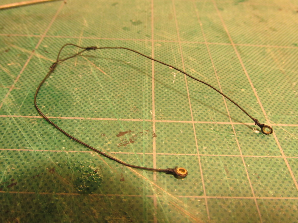
I'm no sailor. and this is my first 3 masted rigging build so I am only going by what I read and see. According to David Antscherl's, The Fully Framed Model, Rigging a Sixth Rate Sloop of 1767-1780, Vol IV Page 46 Section 15.22 these were pendants were used with various block and tackle as a means of hoisting things before the upper masts were stepped and installed. It appears they remained in place until until such time the upper masts were removed and used to take things apart. Whether they were used in the interim I have no idea.
-
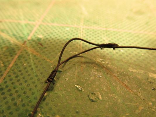
The first pendant I made was the Mizzen Mast’s which required served .45 mm line with thimbles at each end. The other masts will require a thicker line. Two pieces of line were served and a thimble added at one end. Then the lines were overlapped and pseudo sliced in two places to create a split in the line. Overall the finished length was 7”.

- 974 replies
-
- 4
-
-
- rattlesnake
- mamoli
- (and 1 more)
-
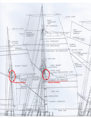
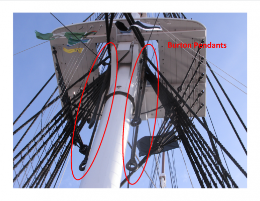
For those who have been following this build log I apologize for going slow, but these last few weeks have been even slower. Due to Thanksgiving, which for my family lasts about a week not just one meal. I visit my sister in Colonial New England, specifically the Hartford Connecticut area. She had a small gathering of only eight people. Last year it was 19 people, which was not her largest party. How she does it by herself mid you, I still haven’t figured out. In addition there have been some personal events with my 96 year old Mom in Florida who still resides at home. BTY, while I was in Conn. I got a chance to visit Old Ironsides, the US Frigate Constitution. She is due for drydock in March I think, so this was my last chance to see her before they strip her down for refurbishing for the next 3-4 years. As it turned out, they had already removed her top deck guns and all of the yard arms. More on that further on. Burton Pendants Continuing to follow David Antscherl, his next section was the making of the Burton Pendants. As he explained it: “Burton Pendants are served lines that were slipped over the mastheads prior to stepping the lower masts in full-sized practice. Blocks and tackles were then attached to them for hauling up to the tops and other items of rigging.” Neither kit plans addressed these pendants nor did Harold Hahn’s plans. However, I recently came into possession (from a fellow Rattlesnake builder) of the plans used to build the Rattlesnake now at the Smithsonian. These plans do show the pendants and they agree with Antscherl as well as Lennarth Peterson’s Rigging Period Ship Models. I learned that these pendants are more common on the bigger ships but do appear of some of the smaller ones. Since I’m the captain of this ship, I elected to add them. The plan image below is from the Smithsonian plans. While I was at the Constitution, I naturally took pictures. Because the yards had been removed, there was less congestion of the lines and low and behold, I caught a view of the Burton Pendants!
- 974 replies
-
- 4
-
-
- rattlesnake
- mamoli
- (and 1 more)
-
I found making those #$%#%$# stairs was a b*tch. You made it look easy. It seems to me that sanding those steps ends at a perfect 90 degree angle had to be tricky not to mention gluing them perfectly vertical. Good job!.
- 264 replies
-
- 1
-
-
- rattlesnake
- model shipways
- (and 1 more)
-
Thanks for for your vote of confidence, it is greatly appreciated. Thanks also for your quick response. I wasn't familiar with John McKay because I hadn't researched the HMS Victory. I look forward to your resurrected Constitution log, I'm sure it will help me when I finally start construction. That build is still a ways off as I am just starting the rigging for the Rattlesnake after over 4 yeas since I started it. I'm just slow because every step is new to me. But hey, its a hobby!
- 755 replies
-
- 1
-
-
- finished
- caldercraft
- (and 1 more)
-
I have been following your log for some time now picking up all kinds of useful information, techniques, and tips. One day I hope to obtain some of your skills. Although I would probable never attempt the Victory (not at my skill level), I do plan on building the MS Constitution which still might be a bit of a reach. You have however piqued my interest to the models used in the images in your last post. Whose's Constitution model are these images from and where can I see more? Who is this "McKay" that you speak of and where can I see his work? Thanks for sharing your knowledge
-
Tom, Thanks for the praise, all flattery is greatly appreciated! 8-) No work is being done this week as all my time is being devoted to family for Thanksgiving. In my family, it has never been a one day affair. There is too much food to eat in just one day. Hope you (and everyone else) have a good and safe holiday. Jonathan
- 974 replies
-
- 1
-
-
- rattlesnake
- mamoli
- (and 1 more)
-
Just discovered and read your log today. As a fellow Rattler, welcome aboard. I've been working on my model for over 4 years now (I'm a real slow builder because this is my first POB build and knew nothing about ships). My model however is from the Mamoli kit, same scale but slightly different internal structure. In addition mine is kitbashed following Robert Hunt's Practicum. You've received some real good advice so far, I know it's helped me as well. A couple of books were recommended to you and I would like to add a few more. My reference library started from zero and has grown exponentially over the years. Rigging Period Ship Models, Lennarth Petersson The Masting and Rigging of English Ships of War 1625 - 1860, James Lee The Fully Framed Model, Vol. III and Vol. IV, David Antscherl Looking forward to your future posts Jonathan
-
Just ran across your Connie build today. You've picked quite a popular ship. I too am among the many who plan on building this model. Presently I working on another of Bob Hunt's Practicum models, The Rattlesnake, my first POF build. I have Bob's practicum for the Connie but have not read it as I won't start my build until I complete this present project (4 1/2 years and counting). I would like to pass on words of praise and caution on Bob's practicums at least from my experience. As good as his practicums are, Bob is human and even he makes mistakes. I found a number of them in the Rattlesnake practicum. So don't take everything he says as absolute. Dry fit, verify dimensions, check wood choices, etc., and read everybody's build log you can lay your hands on. There is a lot of good ideas and problem solving solutions to be found in those builds. In my case, Bob was writing the Rattlesnake practicum at the same time he was writing and building 3 others, all with deadlines to meet. I don't know of the pressures he was under if any, when he was writing for the Connie. As a result, in the later chapters I began to notices he was taking short cuts, not giving all the details, etc. In many cases he only built details on one side of the model and didn't even rig the ship but just explained how it was suppose to be done using the kit plan diagrams. All that being said, I could not have built what I have so far without Bob's guidance. I still would recommend to anyone to use his practicums. I plan to follow your build as I too consider myself a novice even with a partial build under my belt to learn from your successes and mistakes. I also plan to follow the more experienced builders to learn their skills. Just remember don't rush, take your time, no one is pushing you; it a hobby Take Care Jonathan!
-
Beautifully done! Do you have any images of the step by step process on how you made those stars?
-
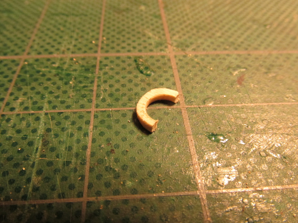
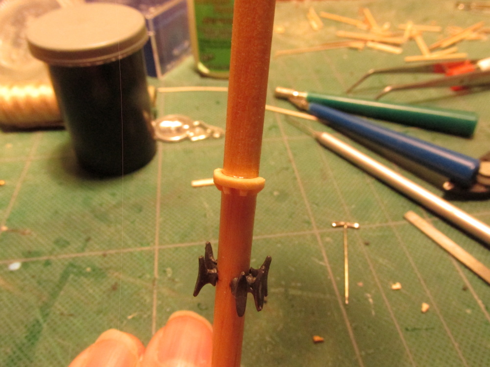
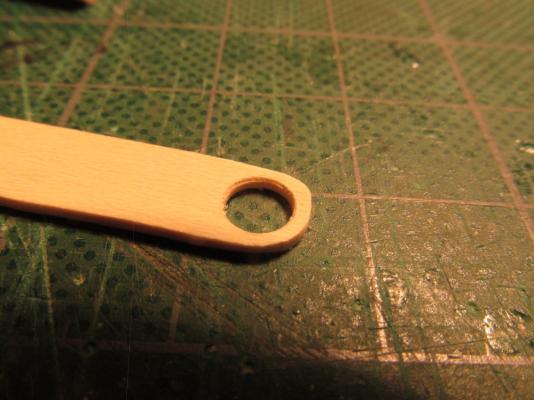
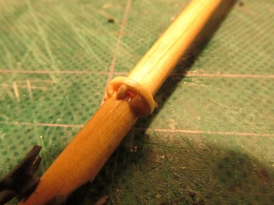
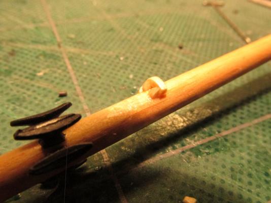
In addition to the cleats, the Mizzen mast had an additional feature which showed up on all the plans except Mamoli’s. This was a “rest support” (my term, don’t know what the nautical term is) for the boom. The only view I had was from the side so I just winged it. First I traced the mast onto a piece of 1/16” stock boxwood to get the inside diameter and then drew a larger concentric circle around that about 1/16” wider. With progressively large drills, the center was cut out and then the outside edge was filed to shape. With a fine saw the “ring” was cut in half and glued to the aft side of the mizzen mast at the height depicted in the drawings. Based on what I could see in the drawings I determined that there were five brackets under the half ring. I cut 5 1/16” cube pieces and with just a touch of CA glue, glued them into place. Once dried and set, with a fine diamond needle file, they were delicately filed to a triangular shape. A touch of Poly-Wipe and it was completed. Sounds simple but I screwed up a number of times with a number of re-dos, but all in all, it seems to work.


- 974 replies
-
- 6
-
-
- rattlesnake
- mamoli
- (and 1 more)
-
Back to the Masts Putting aside the bowsprit for a while (according to David Antscherl) I started to work on the Mizzen Mast. But before I could even start that, I wanted to make sure there was nothing left to put on the mast before it was locked into place. And lo and behold there was. Looking at views other than the construction views of the masts, I discovered there were cleats that had to be installed, six per mast. Even though this is a kit bash and not a scratch build, I felt a bit guilty using the kit’s cleats instead of making them myself because I've scratch built so much already; but use them I did.

- 974 replies
-
- 4
-
-
- rattlesnake
- mamoli
- (and 1 more)