JSGerson
-
Posts
2,137 -
Joined
-
Last visited
Content Type
Profiles
Forums
Gallery
Events
Everything posted by JSGerson
-
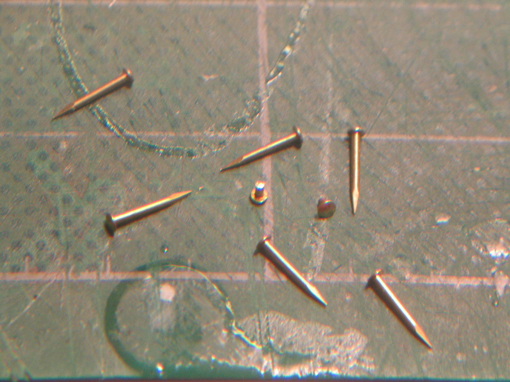
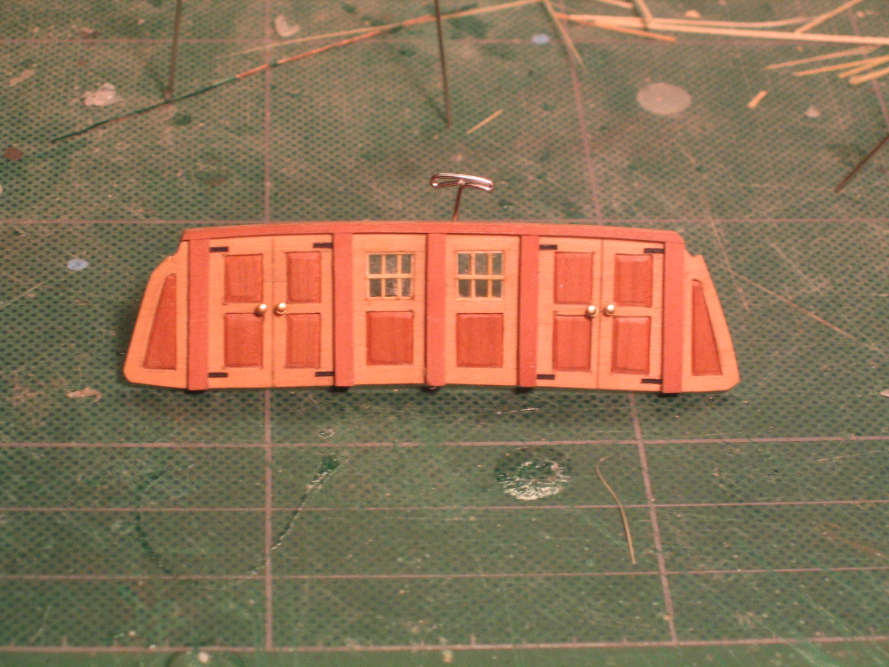
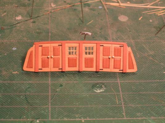
 The door hinges were made from black paper and the doorknobs are the heads of some bass nails I had lying around.
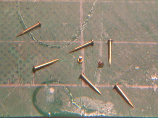
- 973 replies
-
- 3
-

-
- rattlesnake
- mamoli
- (and 1 more)
-
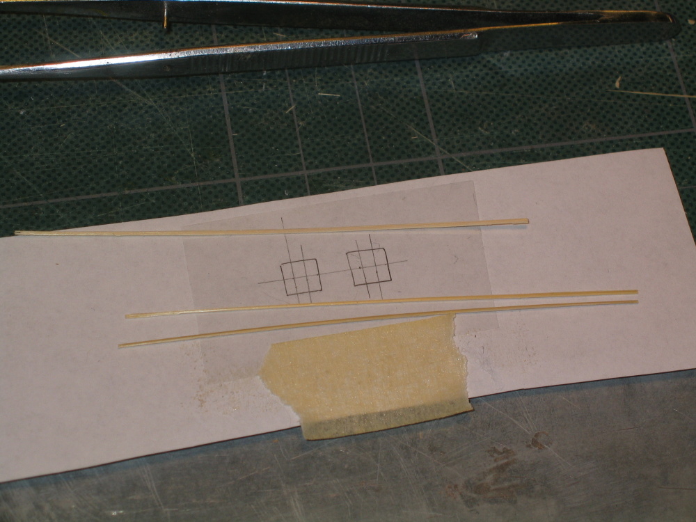
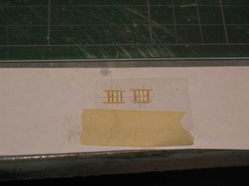
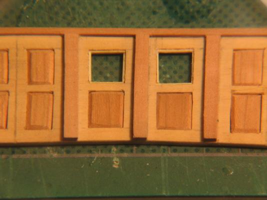
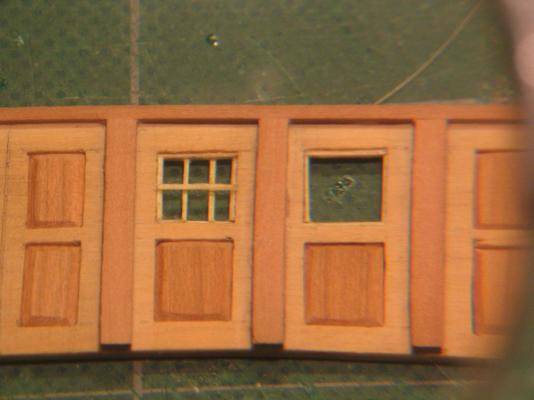
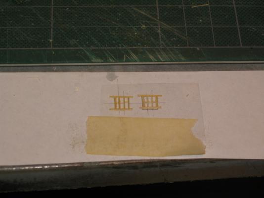
I had some very thin clear plastic film packaging material I received from thing I ordered mail order – perfect for windows. The problem was I didn't know what kind of plastic it was which meant I didn't know what kind of glue to use. The “wood” I was using for the window frames was bamboo, the same stuff I had been using for the tree nails. I use it because I knew from the tree nails, I could make the pieces very thin and straight with little problem and it would hold up. I tried super glue and Weldbond which stuck to the bamboo but not the plastic. Because I couldn't create the frame, I couldn't lift it up to insert into door window opening. It was time for Plan B. The windows are constructed like a sandwich: six pane frame – one large window pane – six pane frame. I created the window frames directly in the opening. That meant constructing the first perimeter frame and the interior frames gluing the wood frame to the wood door. Then I fitted a single piece of clear plastic that covered the whole opening. Finally I constructed the second frame assembly on the other side of clear plastic effectively securing the plastic in place. I wanted to have the interior frames all flush but had too much trouble with the horizontal frame member. The pieces were simply too small to handle, so I just laid the horizontal piece on top of the verticals. Unless one looks at those windows with a boroscope, you can’t tell.
- 973 replies
-
- 3
-
-
- rattlesnake
- mamoli
- (and 1 more)
-
At this point I deviated from the practicum. Mr. Hunt used styrene plastic to construct the door window frames which had to be painted. I didn’t like that. I was going to use wood. Easier said than done. I initially followed the Practicum planning to substitute the wood for styrene. I laid out the windows as described in the instructions but ran into a problem with the window panes.
- 973 replies
-
- 1
-
-
- rattlesnake
- mamoli
- (and 1 more)
-
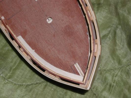
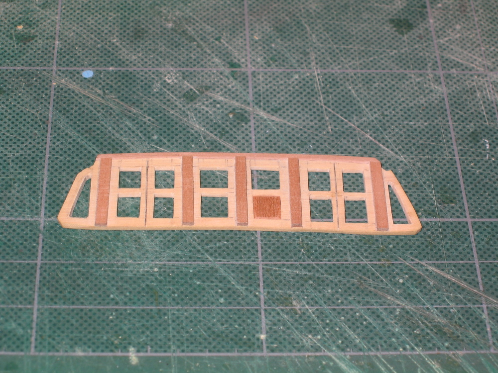
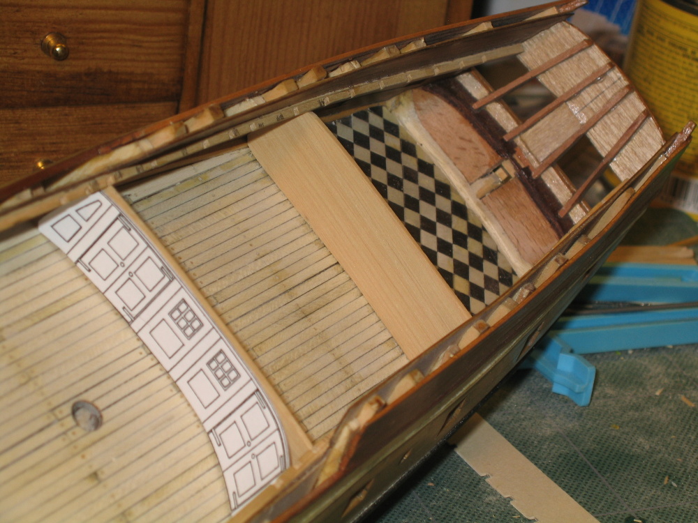
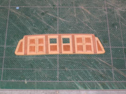
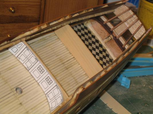
Not only were the windows in the doors cut out, but also the contrasting panels in the bulkhead.

- 973 replies
-
- 1
-
-
- rattlesnake
- mamoli
- (and 1 more)
-
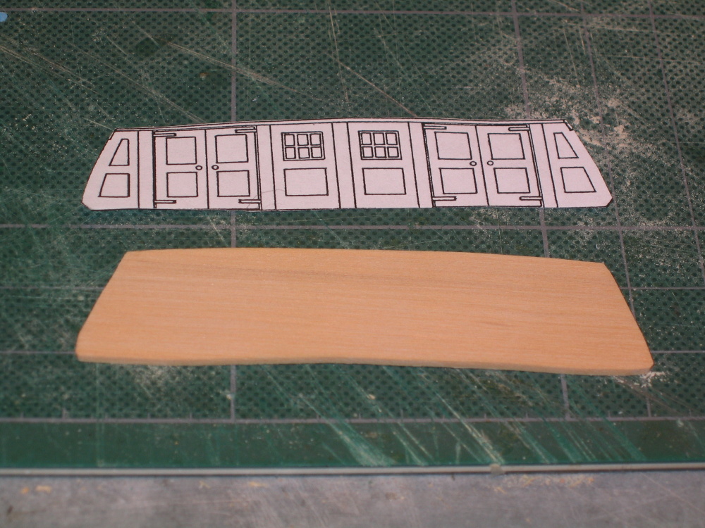
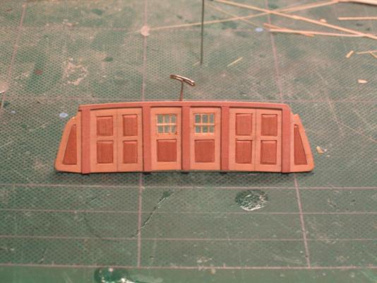
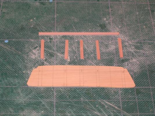
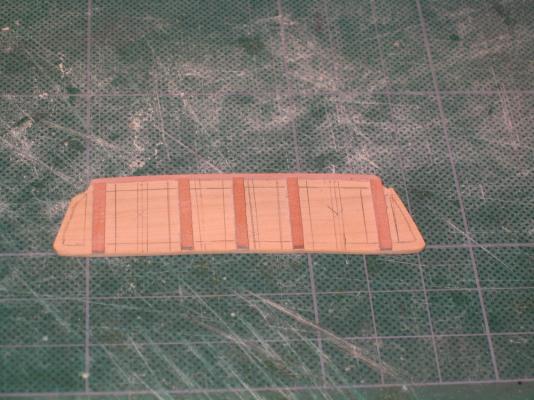
1st Bulkhead Now it was a matter of transferring the lines from plan to the first bulkhead and cutting the appropriate wood pieces and gluing them on.
- 973 replies
-
- 1
-
-
- rattlesnake
- mamoli
- (and 1 more)
-
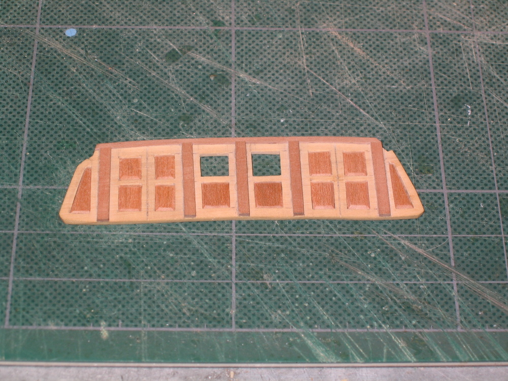
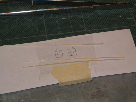
I created the second bulkhead at this stage ahead of the practicum. With no template to work from (neither the kit nor Mr. Hahn plans addresses it) I used the first bulkhead as a rough start and though trial and error created the second bulkhead.
- 973 replies
-
- 1
-
-
- rattlesnake
- mamoli
- (and 1 more)
-
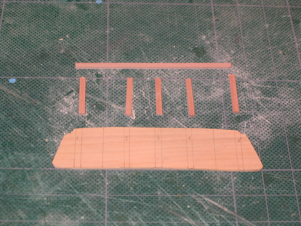
CHAPTER 5 –Deck Details The Bulkheads There are two bulkheads that need to be installed. The kit provided one of them, a cast piece of metal which I won’t use. I will be scratch building both of them. I found this a quite pleasurable task. Either using the Hahn’s plan (or the cast metal piece if you wish) a preliminary template was made out of card stock. WARNING The Practicum instructs (Chapter 5, page 1, §5.1.1, 1st¶) you cut the bulkhead out of 1/16” x ¾” boxwood. I checked my wood package invoice list from HobbyMills and that size was NOT included in my wood package. I contacted Jeff Hayes by email explaining the situation and offered to buy the missing piece of wood. He replied: He then went on to state: Then I discovered another reference to 1/16” x ¾” boxwood (Chapter 5, page 21, §5.3.1, Capstan. After a few more emails, Jeff replied: Jeff went above and beyond the call of duty; not only did he send me the two 24” pieces of wood but I received them via express mail within a matter of days, no charge. I had more than enough wood. Thank you again Jeff, it was a pleasure to do business with you. Jeff was right; I did need the wider piece of wood. The bulkhead was made and fitted as per the practicum. And like the practicum, mine was not perfectly symmetrical, but nobody will notice. If you are building the Rattlesnake to Bob Hunt’s practicum verify you have the proper wood in your package.

-
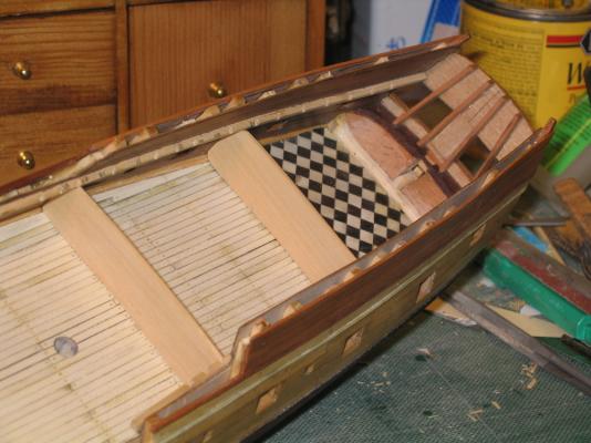
Based on your comment, I went looking for the HMS Fubbs model images and could not find any by Mr. Hunt, even on his website. I did find other modeler's parquet floors for this ship. They were a juuusst a bit more elaborate than my simple checker board, but for a first time project, it was satisfying and fun.
-
Ignorance is bliss. I didn't know it was suppose to be difficult, so I did it!
- 973 replies
-
- 1
-
-
- rattlesnake
- mamoli
- (and 1 more)
-
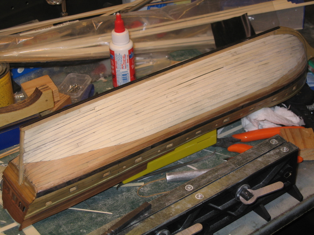
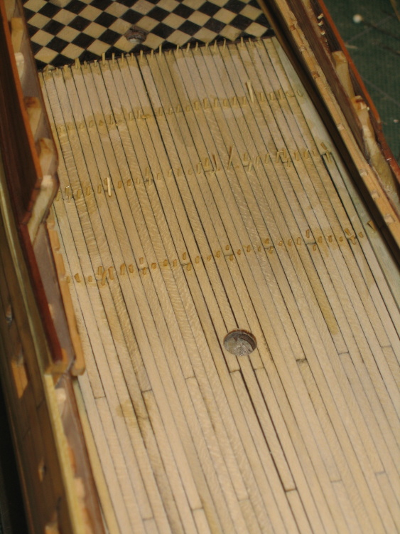
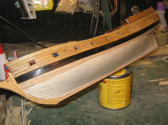
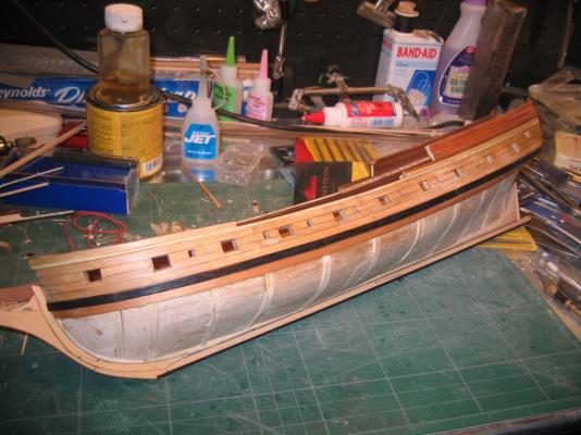
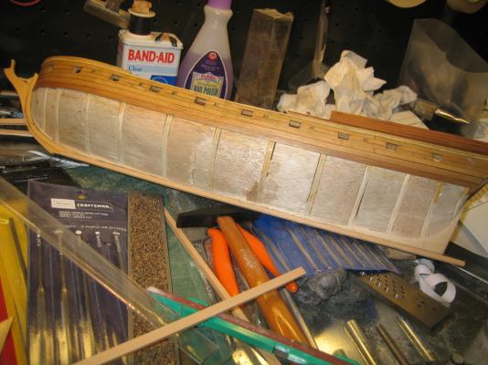
As anyone can see, this planking job leaves a bit to be desired, but there it is. If I were to do it again hopefully it would be better. Tree Nails The tree nails are lined up along the bulkheads, two treenails per width of the plank. At the butt joints the tree nails are staggered. End of Chapter 4

- 973 replies
-
- 5
-
-
- rattlesnake
- mamoli
- (and 1 more)
-
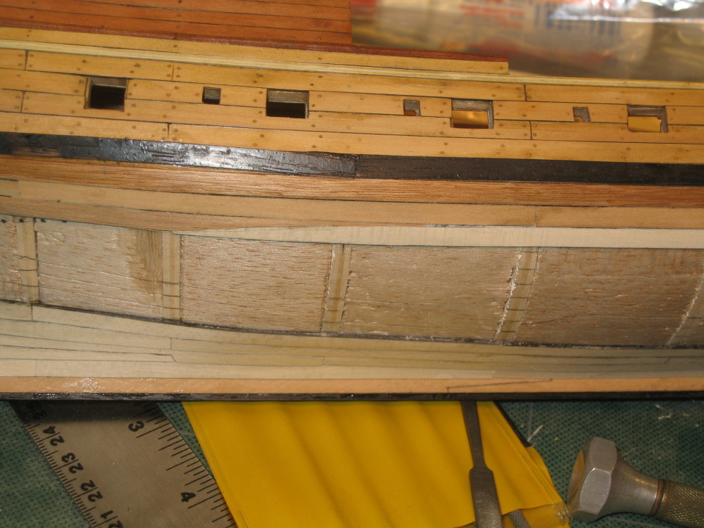
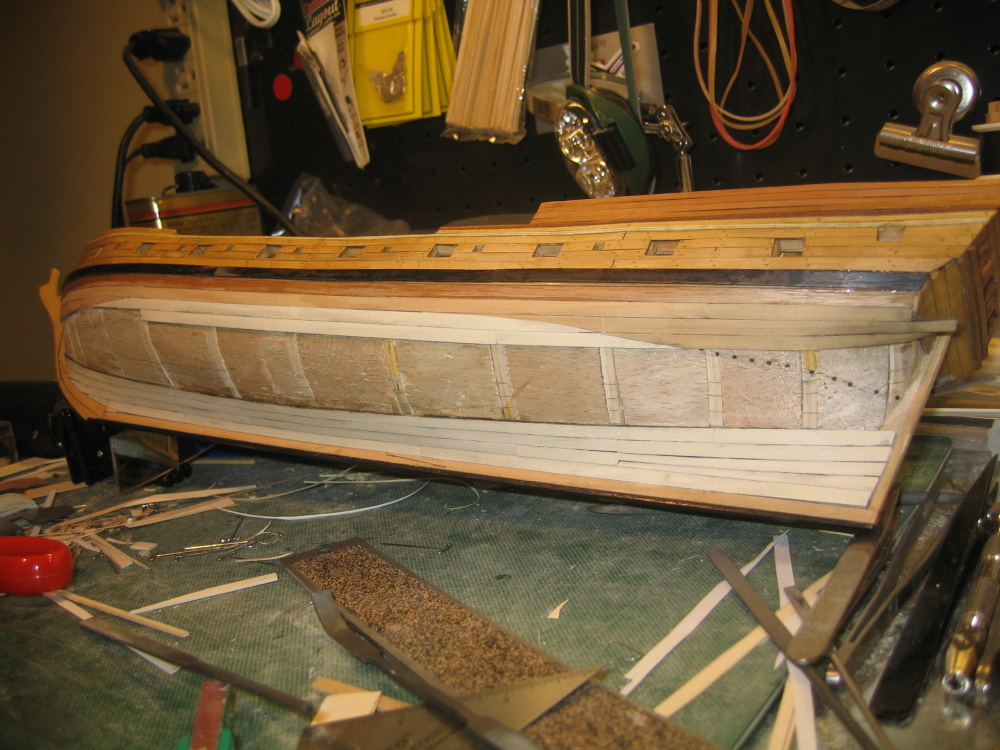
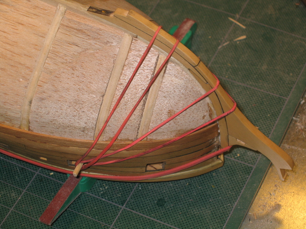
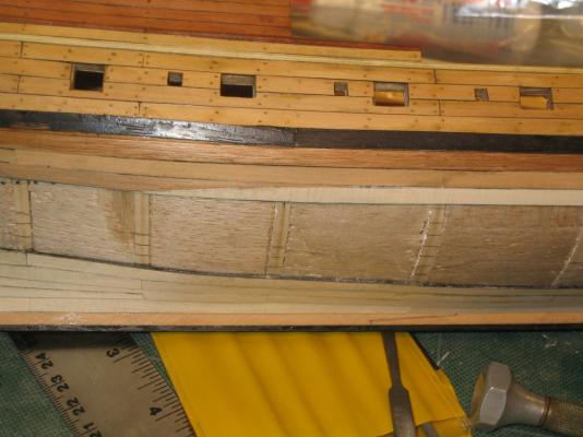
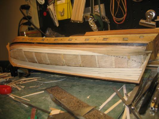
After four courses I decided to also work my way down from the wales to ensure I met the wales properly. Here is where my inexperience began to show. I could already see that some of the planks where going need being split but when and how eluded me. As I stated before reading how to do it and actually doing it is not the same thing. I plodded on. When a holly plank crossed the waterline it was cut at the waterline and continued as boxwood which is slightly darker wood.


- 973 replies
-
- 4
-
-
- rattlesnake
- mamoli
- (and 1 more)
-
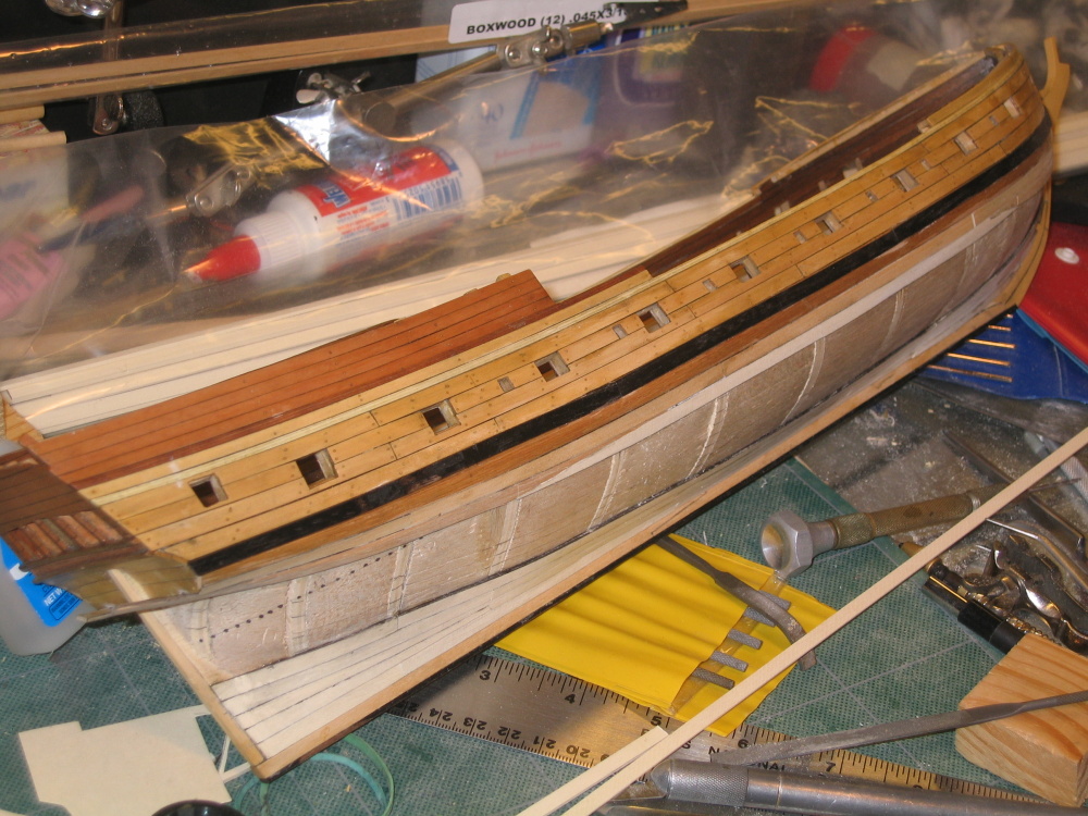
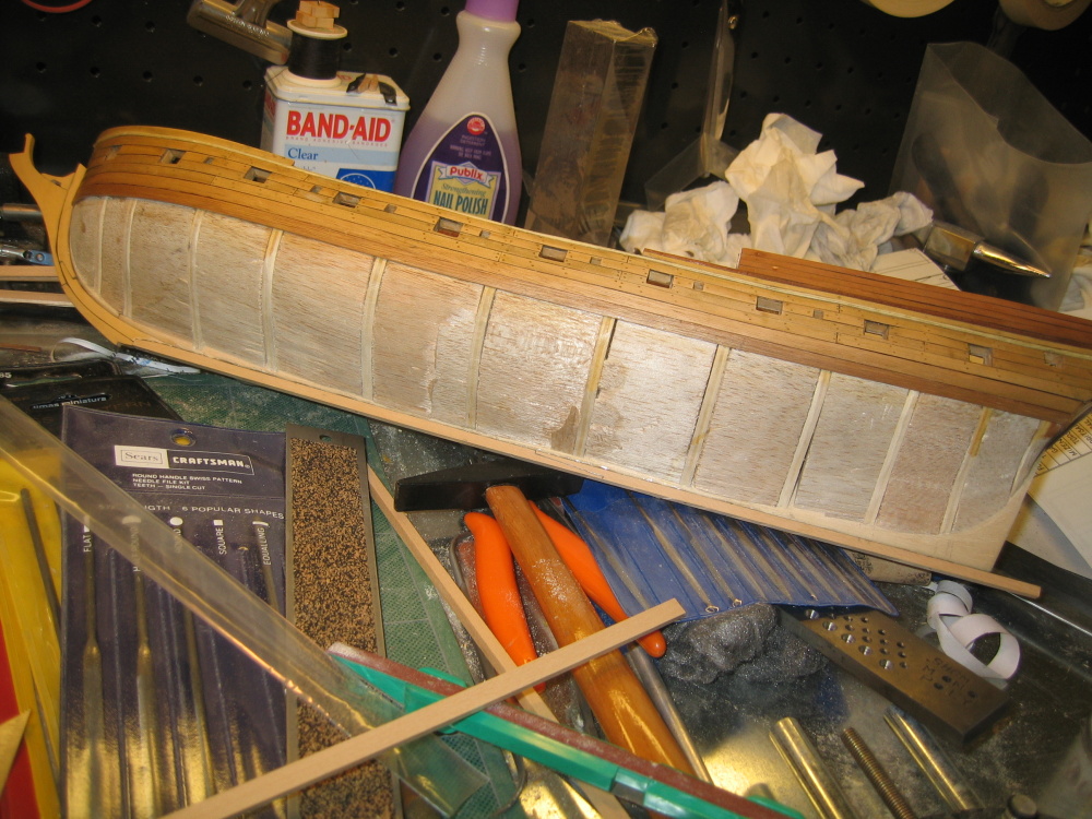
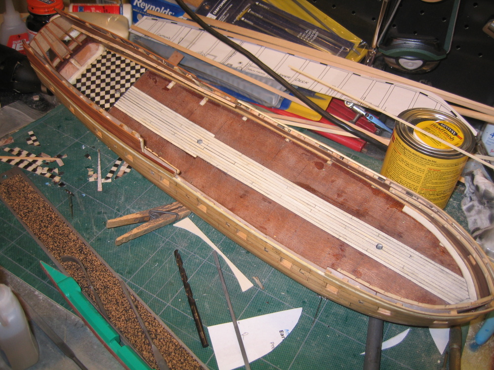
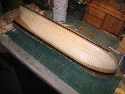
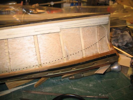
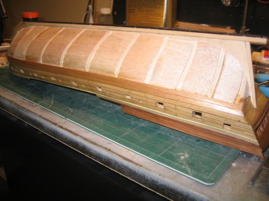
Lower Planking The first thing that was done was to mark the water line 1/8” below the wales at bulkhead #6 using a homemade surface gauge which nothing more than a vertical post with a horizontal pencil firm attached 90º to the post. Leveling the model as best I could, a line was scribe around the hull. I knew it was level if my end point matched my starting point and I was 1/8” below the wales on each side of the hull. Then I marked the scribe line with dashes using a sharpie pen. The planking started at the keel using .045” x 3/16” holly planks. Holly is a very light colored wood. The butt joints are at the bulkheads.
-
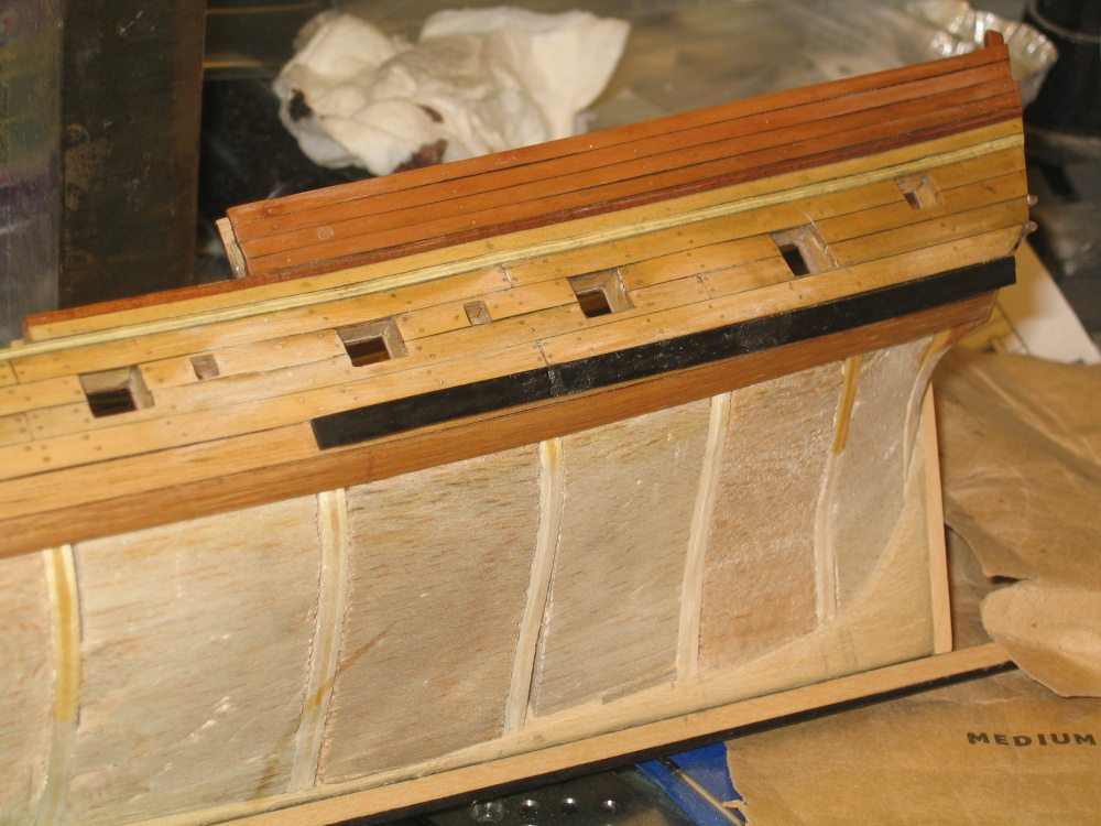
The Wales The practicum explains: The wales are to be made from ebony, it my case black stained walnut. Two rows of planking make up the wales. The first row is attached now and second row later. “The wales are somewhat different than what we normally see on most ships. There is a definite plank thickness difference in the top wale plank and hull planking. However, the bottom wale plank is flush with the top row of the lower planking. Normally the plank beneath the wales is called the diminishing plank and is slightly thinner than the wales. But on Rattlesnake, the wales are slightly tapered so as to form a smooth flow into the lower planking, no step down as normally seen.” The first plank of the wale is glued from the stern to the fourth bulkhead from the stern on top of the basswood wale that was installed earlier in Chapter 2 This was continued to the stem.

- 973 replies
-
- 1
-
-
- rattlesnake
- mamoli
- (and 1 more)
-
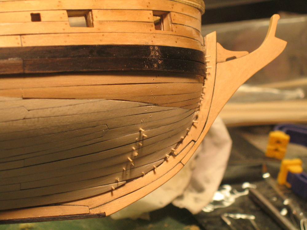
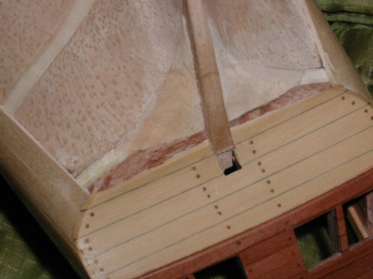
Once the stempost was installed, the false keel was stained black, fitted, and glued on.
-
The sternpost is tapered for thickness and along it length. Again using a photo from the practicum.
-
You will notice that the keel is slightly longer than necessary. This is so the stem post can be fitted. You will also notice that the stem still has a notch. This is where the false keel will fit in. However before that is installed, the stempost needs to be. First a square opening in the counter is made. This photo is from the practicum as I didn’t one of my own.
-
The practicum indicates that the keel is normally made of more than one piece of wood, but for simplicity one piece will be used. However where the joint would have been a bit of sleight of hand is performed. A lap joint is cut into the wood for show. Shhh…Don’t tell anyone and they will never know the difference! Although the practicum did not call for it I added pins along the keel to help mechanically attach it to the hull.
-
CHAPTER 4 –Planking the Lower Hull As I have indicated before, this is my first real planking project and I’m taking a BIG bite from the apple. The practicum kitbash is following Harold Hahn’s model albeit in a smaller scale. Because the model uses very little if any paint (except black stain in lieu of ebony wood), the hull water line is created with different woods to complicate the planking process. Reading how to plank a hull and actually doing it are two completely different experiences. So due to my lack of the latter - experience, my results are far from perfect. The Stem, Keel and Sternpost Here is where the stem which was the first item created is finally attached to the hull.

- 973 replies
-
- 1
-
-
- rattlesnake
- mamoli
- (and 1 more)
-
Thanks for the vote of confidence. I know we all make them, and I know because I don't have much of a ship building experience I'm going to make some more. It just, do I have to make them all?
-
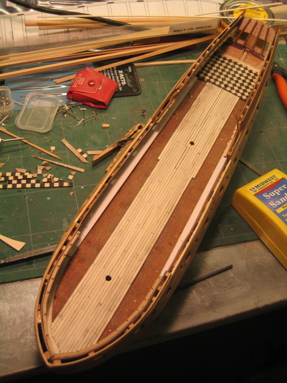
Once all the treenails were installed into the deck, clipped, and the deck sanded down smooth, a coat of poly-wipe was applied over the whole deck. End of Chapter 3
- 973 replies
-
- 1
-
-
- rattlesnake
- mamoli
- (and 1 more)
-
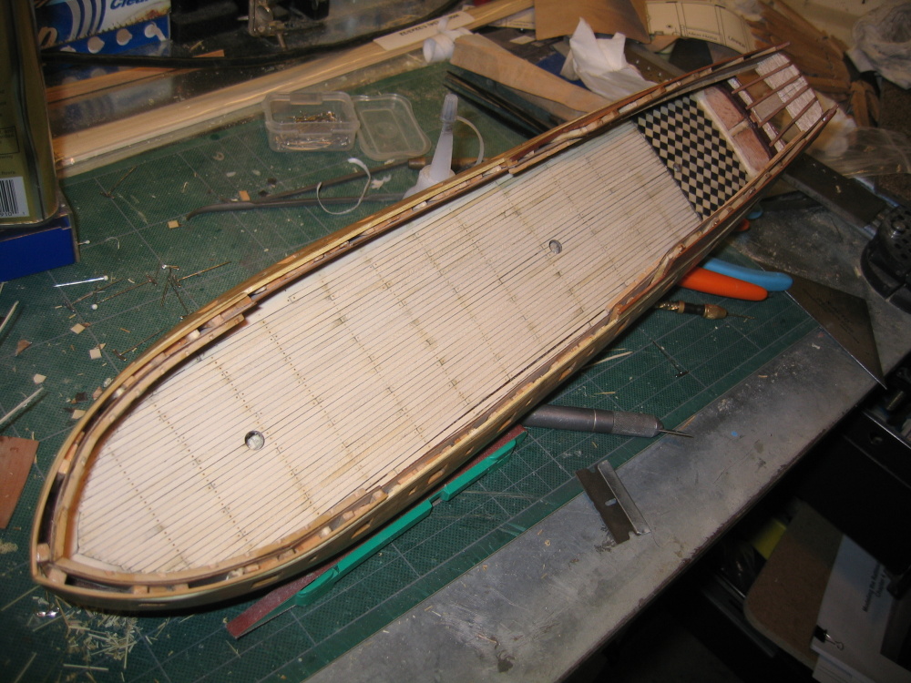
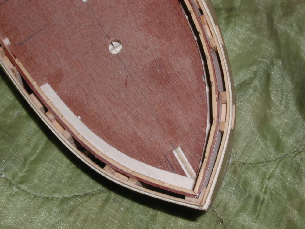
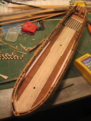
The practicum tells you not to glue the margin plank until the very end. This way, you can remove that plank, to make the plank notches. The planks themselves are glued in. Finally at the end the margin plank is glued down. The trick is to, as the practicum puts it: “You want to have exactly 3 rows of planking left to install between the last row and the margin plank you have just cut. The aft end of the next row of planking you install will nib into the margin plank at the aft end about 1/4" from the end.” Mine was close but not exact…as usual. Tree Nails The deck planks have a single 026” treenail across its width and are installed as before on the beam lines into #69 drill bit holes. Bamboo nails are made using a draw plate and “glued” in using poly-wipe.


- 973 replies
-
- 2
-
-
- rattlesnake
- mamoli
- (and 1 more)
-
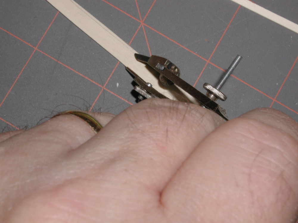
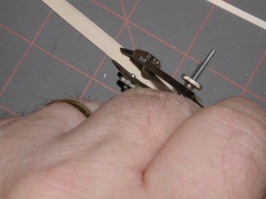
Now the practicum instructs that you fine tune the cut shape using a compass to scribe the 3/16” line along the inner edge as shown in this image from the practicum.
- 973 replies
-
- 1
-
-
- rattlesnake
- mamoli
- (and 1 more)
-
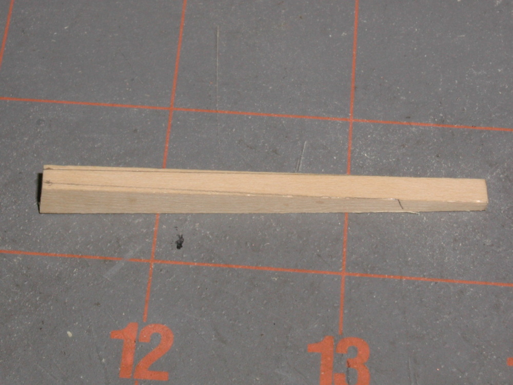
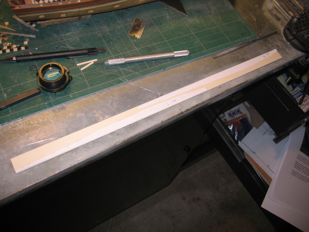
It is time to construct the 2nd half of the margin plank. The plank will continue from the 1st half all the way back to the parquet floor. A template is made as before but ¼” wide and cut the stock wood.

-
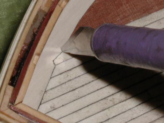
As the planking approaches the margin plank, a notch is created starting from the 5th plank from the center. The plank is then trimmed to fit. After five rows on each side of the centerline, you are instructed to stop once again. The first image below is from the practicum.

- 973 replies
-
- 1
-
-
- rattlesnake
- mamoli
- (and 1 more)
-
The margin plank is cut out and installed. The image below is from the practicum as I don’t have picture of my model at this stage.