Thistle17
-
Posts
1,053 -
Joined
-
Last visited
Content Type
Profiles
Forums
Gallery
Events
Everything posted by Thistle17
-
 Your deliberate and informative sharing has become an invaluable reference for all of us. And I might add your willingness to share set backs as well as successes is apppreciated. I can't tell you the number of "do overs" I have experienced that have slowed progress and dampened enthusiansim. So when I observe your end result I am encouraged to press on. I get the same encouragement from Bob Emser (The Art of Boat Building) by oserving his methods of work. Don't know how to pay you any better a compliment! Joe
- 840 replies
-
- 4
-

-

-
- winchelsea
- Syren Ship Model Company
- (and 1 more)
-
Are you aware that Syren is in the works for a full POF of the Speedweell in AYC? I saw it recently in a meeting it is quite large. I think near or at 3/8 scale.
Joe
-

I knew that Joe. I think it may be a while before it becomes available and I need a project to keep me going. Speedwell looks attractive because 1/48 POB plans are available with the Antscherl/Herbert book.
You are very lucky to have meetings to attend especially when you can get to see works in progress such as Syren's POF Speedwell. I'm a bit on my own down here in Cornwall UK. But I value these exchanges and all the build logs the more for that.
Thanks for your message Joe.
Fred
-
Fred I do recall that Chuck Passaro of Syren ship models said that 1/4 scale was too small for him to produce such a model. I was surprised by that as he did not elaborate. It may have been related to laser machining. You may wish to contact David Anterschel. He is quite friendly and helpful. Hope I am not mixing the pot too much here..
Indeed nice to connect with you. I will be following what ever your next project is.
Joe
-
-
I had missed your posting of this build earlier. It is truly lovely!!!! I stopped my Winchelsea build for a number of reasons recently and went back to my Cheerful. It has so much merit as your build loudly proclaims. I will pick up the Winchelsea again as soon as I finish ny Cheerful after an unsatisfying start on the her. I made a number of mistakes as well and I think that has a lot to do with one's mindset about the project. From the looks of your work you are capable of any path you choose. Joe
- 113 replies
-
- 4
-
-
- Cheerful
- Syren Ship Model Company
- (and 1 more)
-
Good morning Pete. I happened upon your posting this morning and welcome you to MSW. In addition what caught my eye was the fact that you hail from western NY. I am the chair/facilitator of the Model Shipwrights of Western NY and would like to invite you to join us at one of our hybrid meetings (both in person and via streaming). We have an upcoming one in May before we recess for the summer. If you supply me with an email address I will forward you a copy of our LOG from this weeks session as well.
Joe
-
Always marvel at your craftmanship with hand tools Ron. Joe
-
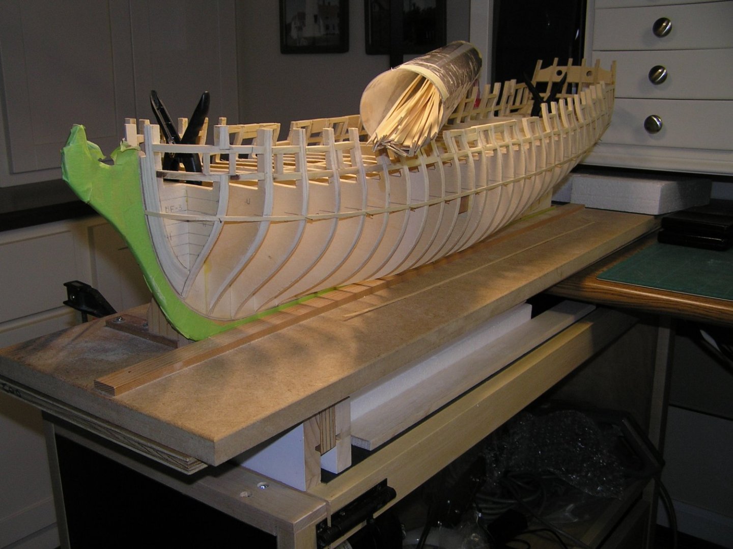
Hard to believe it was 2019 when I ventured out on this project. The skeletal work was completed during that period. It was put aside for other projects including the Florida Sharpie restoration, the Laura Goulart repairs (hard to consider that a restoration) and of course the Mark I PBR. I picked up this project in more ernst in the latter half of 2022. Things haven't gone well if you have read the log. As a result about 2 weeks ago I put the project aside after a cold hard stare at what I had wrought. The stare was somewhat of a one eyed look as I contracted shingles at Christmas that found its way to my left eye this February. I am on the mend but the journey's end is not yet evident. Cheerful has been sitting on the bench staring back at me. It is in its final stages of completeion with all deck furniture, cannon, mast and spars completed. It needs final riiging appointments and a case. So needing a "win" I have returned to it. So I made a decision with Winchelsea. I have decided to shut this build down for the time being. In this interim I came across the components for the skeletal structure and Chapter 1 from an MSW member who has decided against the build. I purchased his components for a very reasonable price. The package arrived yesterday. First impressions when I opened the box was that the plywood material was superior to what I had bought (I elected to fabricate my own skeleton). That is encouraging. So as the song goes "you have to know when to hold 'em and you have to know when to fold 'em"! But I am not walking away.!!!!!!! Joe
-
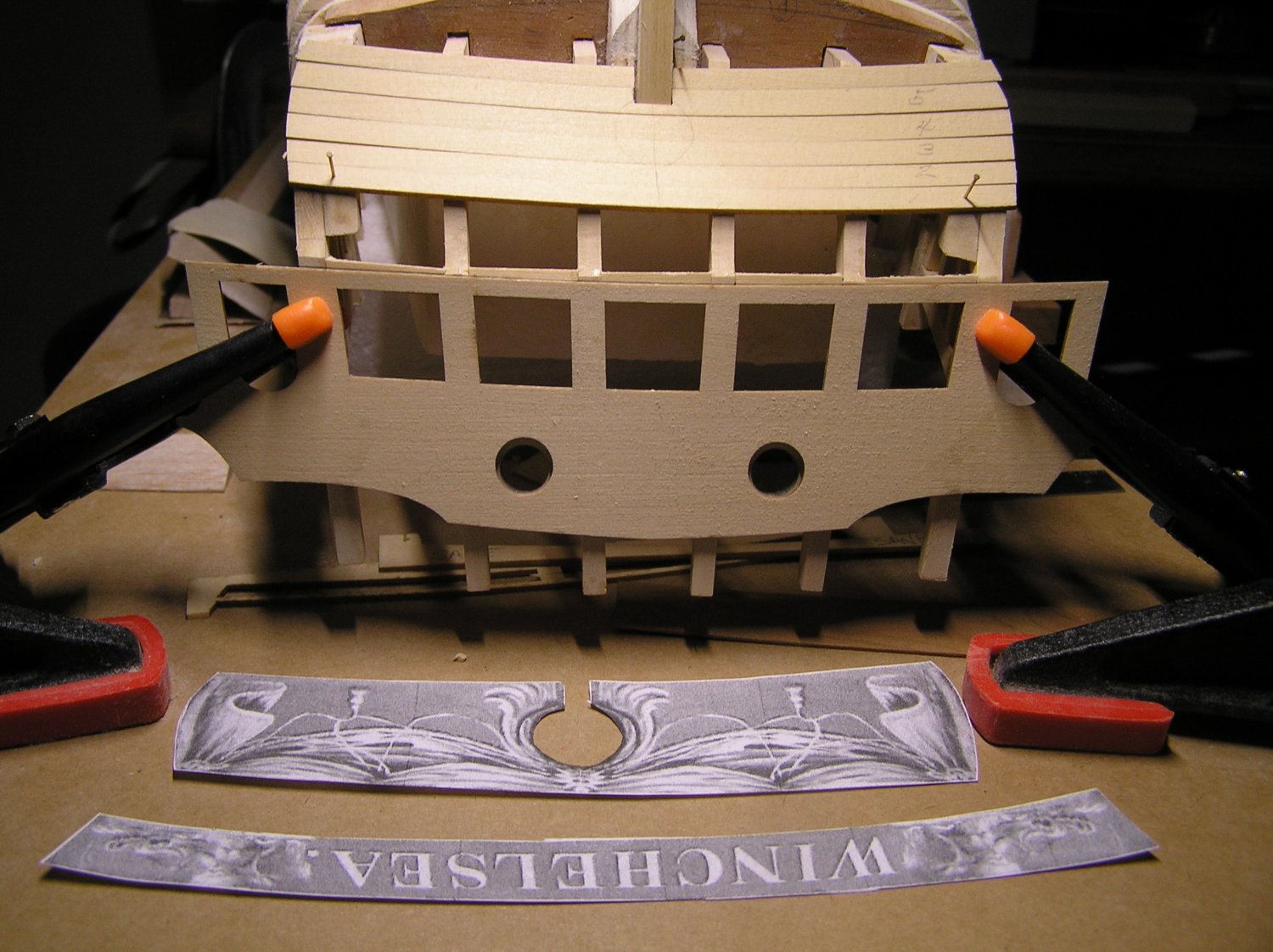
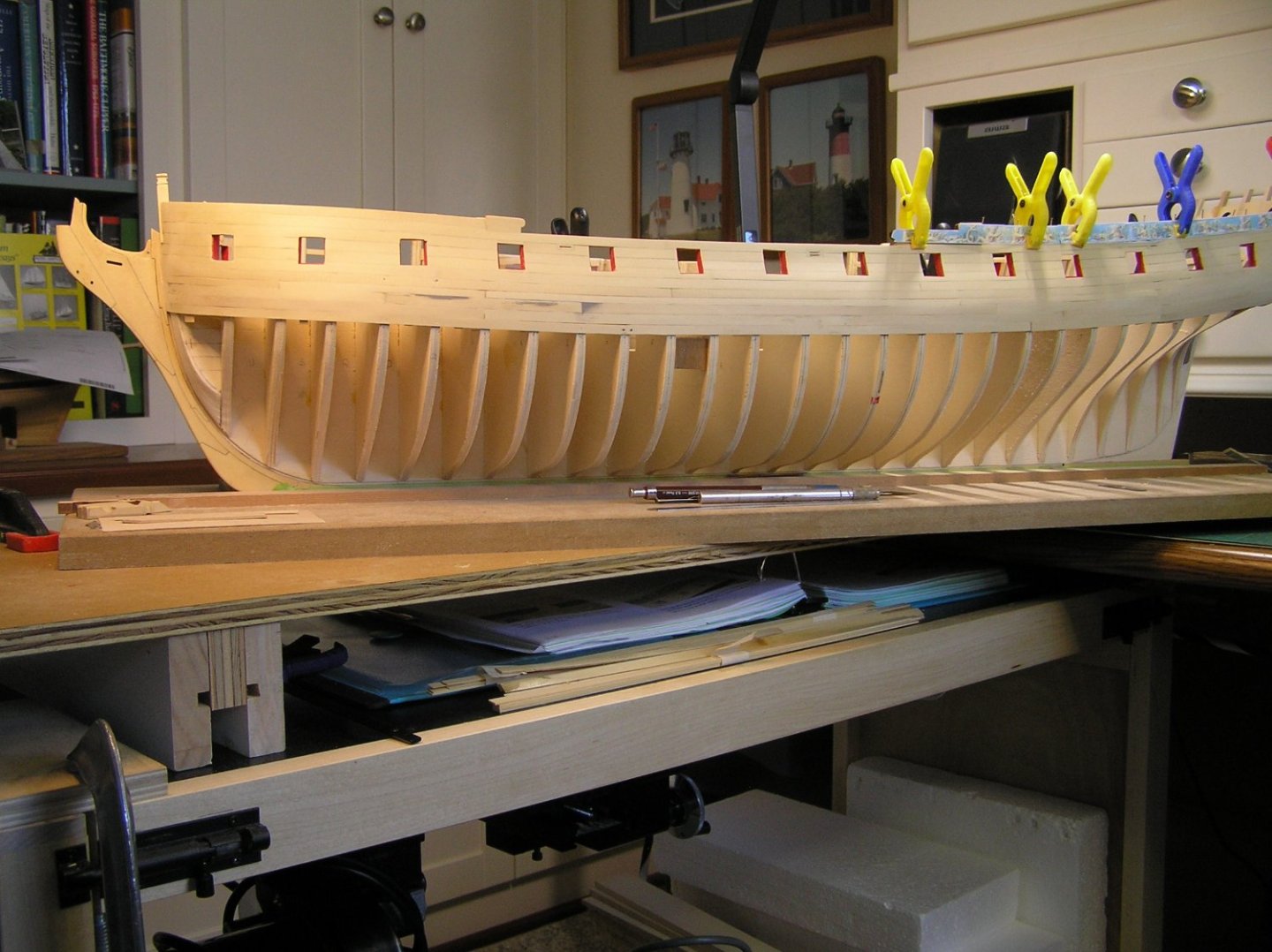
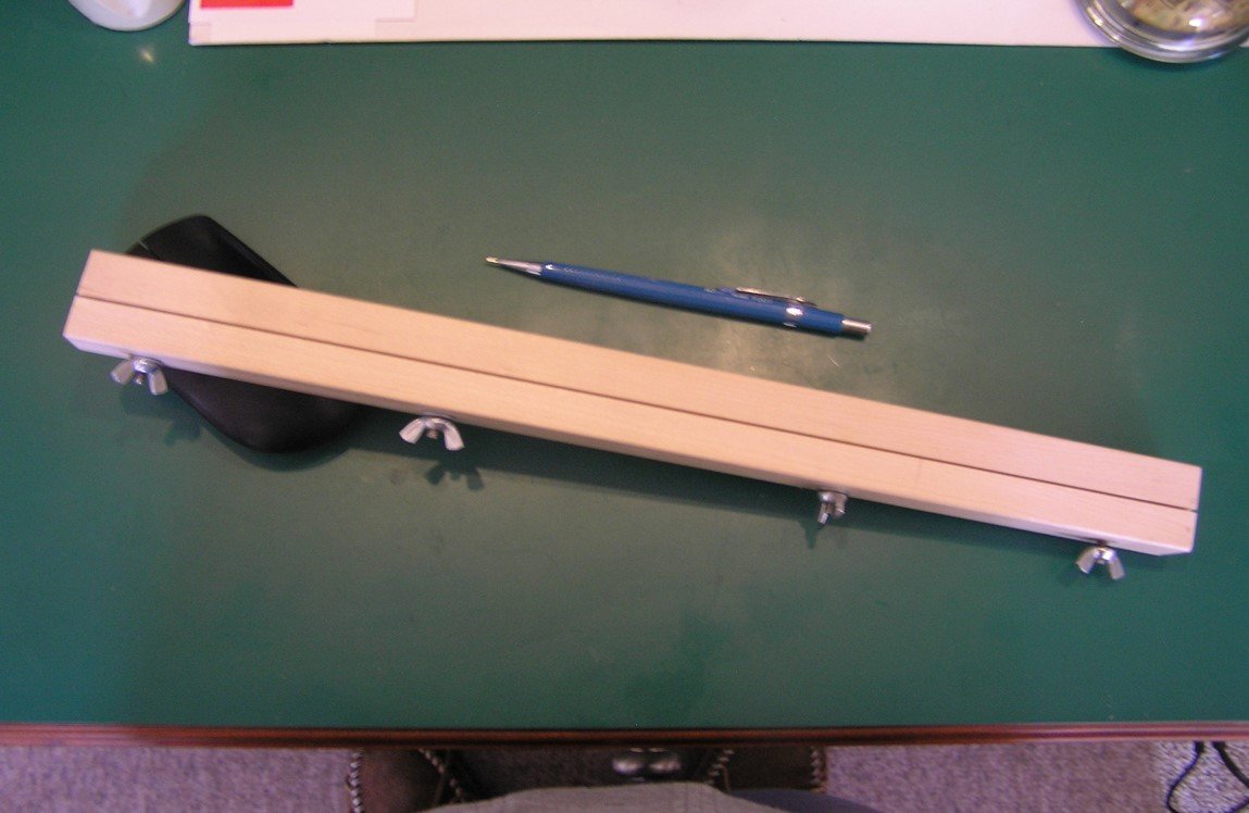
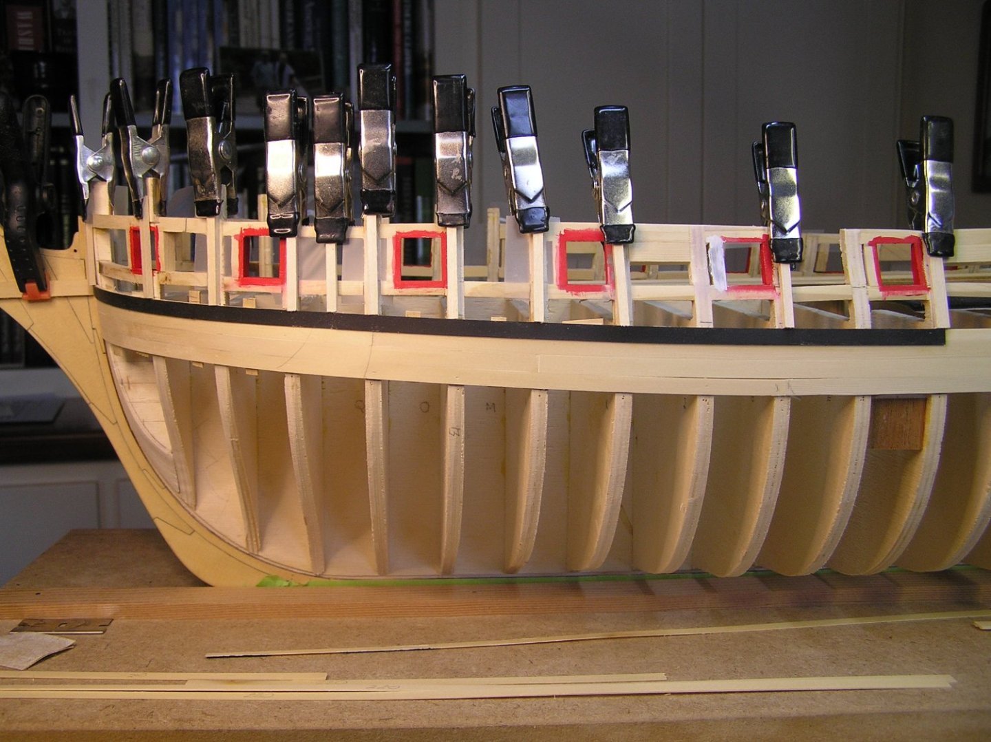
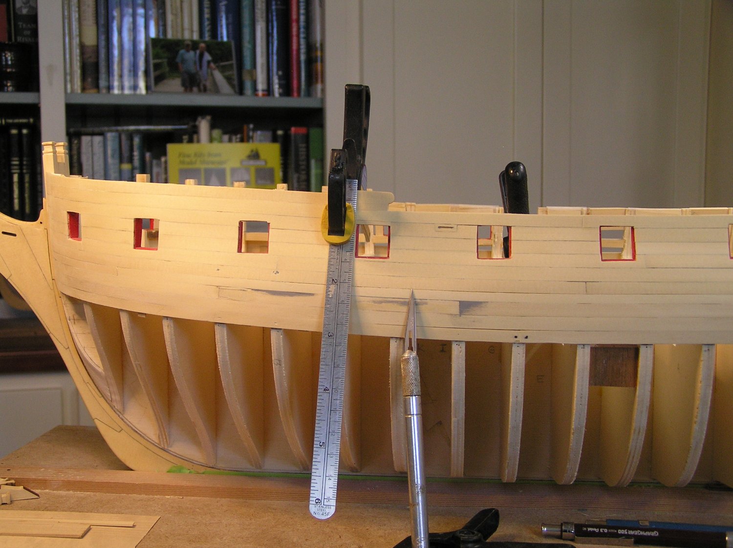
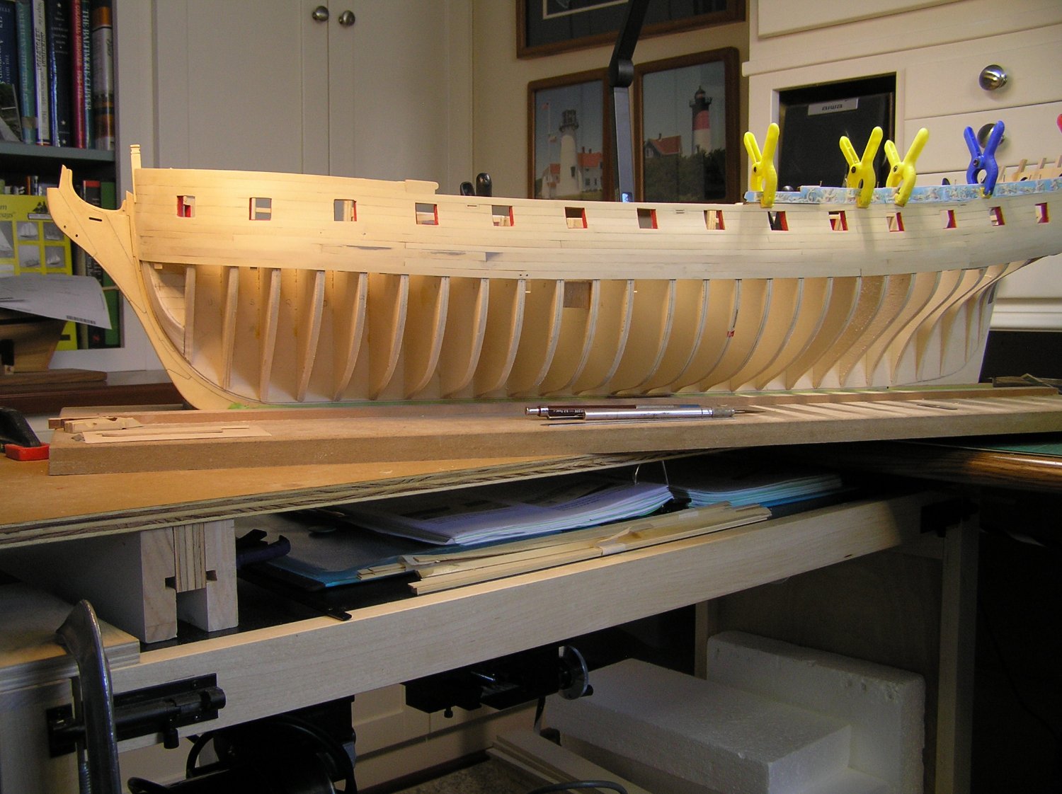
Trying again to make a log entry with photo(s). I have completed the port side planking above the first layer of the wales. The whole effort was an experience in working with this new wood AYC, the model complexities and my relearned or new techniques. Let me comment a bit about the material as I am a bit surprised no one has to date. Overall it is a good material to work with. It does have its own subtle characteristics beyond handling. In bending planking for the bow I did have a few planks shatter at their ends, even after heat bending on a form, at the bow. I suspect the billet end had dried out a bit. Cutting back the plank somewhat allowed usage elsewhere. The second more troubling but correctable problem with AYC I found is what I will term beam deflection tendency. Even with the closely spaced bulkheads it seemed in some cases to bow under the pressure of sanding. Not all planks, just some. The only solution I found was that I had to add a veneer backer across several planks internally to allow uniform sanding. It nevertheless is a easy wood to work with. Well here is the port side planking progress in the attached photo. The first layer of wales recall was salvaged after too anxious a start (and incorrectly so) of the second layer. I did not attempt the rather complex planking "tabs" above and below the gun ports as I thought I was at the limit of my skills. Also it was evident all that difficult work, even if successful was going to be obscured by the frieze application. Gun ports as many of you know, all 24 for a side are quite difficult. I had made a set of gun port plugs with a 1/32 frame around the perimeter that fit snuggly into each recess. The intent was to use them as a stop guide for the ensuing planking. For me, after a few attempts, they were abandoned. Any variation in match up to the banded perimeter became a glaring error when removed. It just shouted at you! To correct any of these early imperfections I ended up hand trimming the openings with a scapel and a guide as shown in the setup photo below. A metal rule with sand paper attached to the rear to add traction kept it in place along with the clamp. It was a tedious, nerve racking effort but I was loathed to rip out yet more planking off. After all that and with some manipulation of plank widths I ended up with the results shown. I was relieved the frieze tryout it came out correctly as can be seen in the stern area with its temporary placement. Joe

-
You folk are so supportive! I appreciate your kind words. All your works are inspiring and drive me on. It reminds me of when I was playing ball. I always wanted to play with those that were much better than I. It raised my game even though there were some hard knocks along the way. Anyway I am nearly finished planking the port side up to the sheer after fine tuning the wales and of course removing my incorrect interpretation of the 2nd layer wales. So far with a little retuning of plank width milling I am coming out quite well. Imagine that! Cutting out planking around ports is such an arduous and frustrating task. After more than a few plank discards I think it passes muster. I am using this shop made plank clamp to hold strakes that have been premarked for cutout and then one by one carving out the port opening. A little sanding using a dummy port plug with 1/32 built out sides gets me in the game. Joe
-
In confering with Rusty this morning I now know I had read (and reread) the monolog incorrectly. Sometimes information sequency or at times too much information can lead to incorrect interpretation. Nonetheless I own the error. I updated my drawing to reflect the correct interpretation of the wales. So I will deconstruct what I have done and finish the 3/64" planking above the wales and at least the two lower strakes below the wales. Joe Wales.draw (1).pptx
-
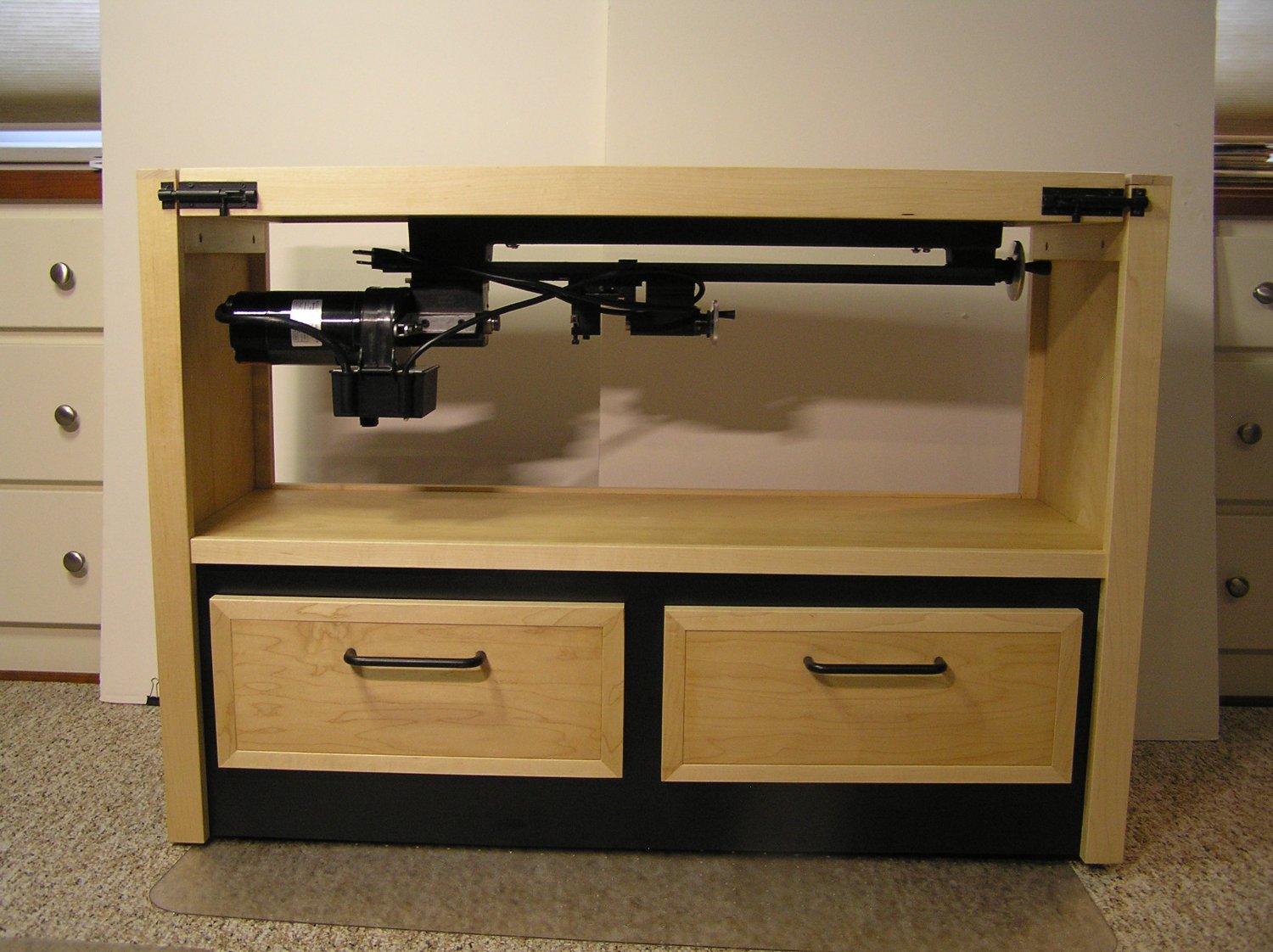
Maximizing Model Work Area: Lathe Table
Thistle17 replied to Thistle17's topic in Modeling tools and Workshop Equipment
Thanks Bob! It has actually turned out to be quite functional just for the table top and working on Winchelsea. I just ordered some shop wheels that are low profile that will also give me a bit more outboard stability when rotating the top to the lathe function. It is well balanced and stays at rest when the locks are open but there is quite a bit of rotational imbalance when it is rotating to the lathe function. Joe -
Maybe it is time for me to call a 'time out" on myself. I had quite a time milling my 1/64, 2nd layer wales stock until I took the time to set up the saw with a new blade. modify my cut off jig to work on my larger table top. Then and only then was I able to fine tune the strakes to the desired thickness. To make the story a tad longer I found I was eating up the cut strakes a bit getting the butt placement so I was hesitant moving the setup until I understood the consumption. Hence the start of the top black strake. I now realize that I will need to sand the black strakes a bit so indeed it was only a good idea to do only the edges with the pro Marker. I will either rip it off or finesse that one in place and return to the regimine layed out. Joe
-
I learn so much from other, reading posts and confering with those that have advanced before me. Truly a gift! After completing the wales first layer on both sides, I was anxious to try my hand at the second layer. Stuntflyer coached me through the process and I must admit it is quite straight forward. One justhas to progress slowly and deliberately. Mike's "stops" to align the black strake at the top is such a simple but effective measure. I colored the top edge with a Winsor Newton Pro Marker, XB Black, rather than paint it with acrylic so as not to have paint build up on the back side. Since the strake from the bow was too short I 'buried a butt joint under the anchor lining and then continued on to follow the pattern. That void in the first layer wales at 'G' I caught too late. It is such a smooth run that breaking the joint and reclamping I anticipate will foul me up with the lower planking. So I made the wales strakes just a tad wider than the 7/32" so the second layer will over lap by just a tad. Joe
-
Your work and results through your photos tell it all Glenn! May i ask what camera are you using? Joe
- 840 replies
-
- 2
-
-
- winchelsea
- Syren Ship Model Company
- (and 1 more)
-
Thank you Canute. It was a journey to get here Covid isolation and all. Happy it is done and I will post a final photo when the diorama is finished by the museum staff. Joe
-
The purpose of this post is more of a personal nature than news worthy to others. With my committment to the Mark I PBR completed I can be more focused on this project. Today I milled the wales first layer planking out of AYC that I happened to have. After confering with the "master' it was suggested I use other than the stock supplied as future need may arise. The wales have been carefully aligned (even checking the P/S height to ensure symmetry after slight adjustment). So now I am ready to start and this post is a marker to see how long this is going to take. Joe
-
Thank you for the recognition. I must reiterate it was a group effort by 6 people but in the last year it was just 3 of us. Joe
-
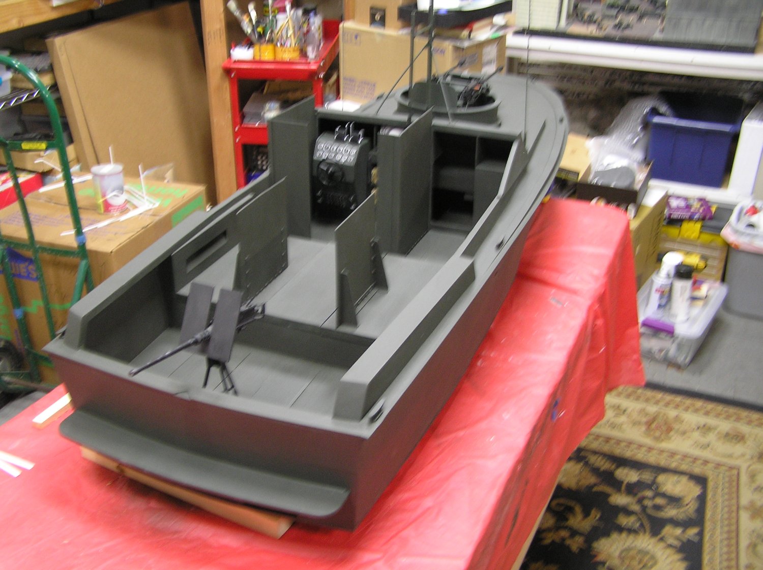
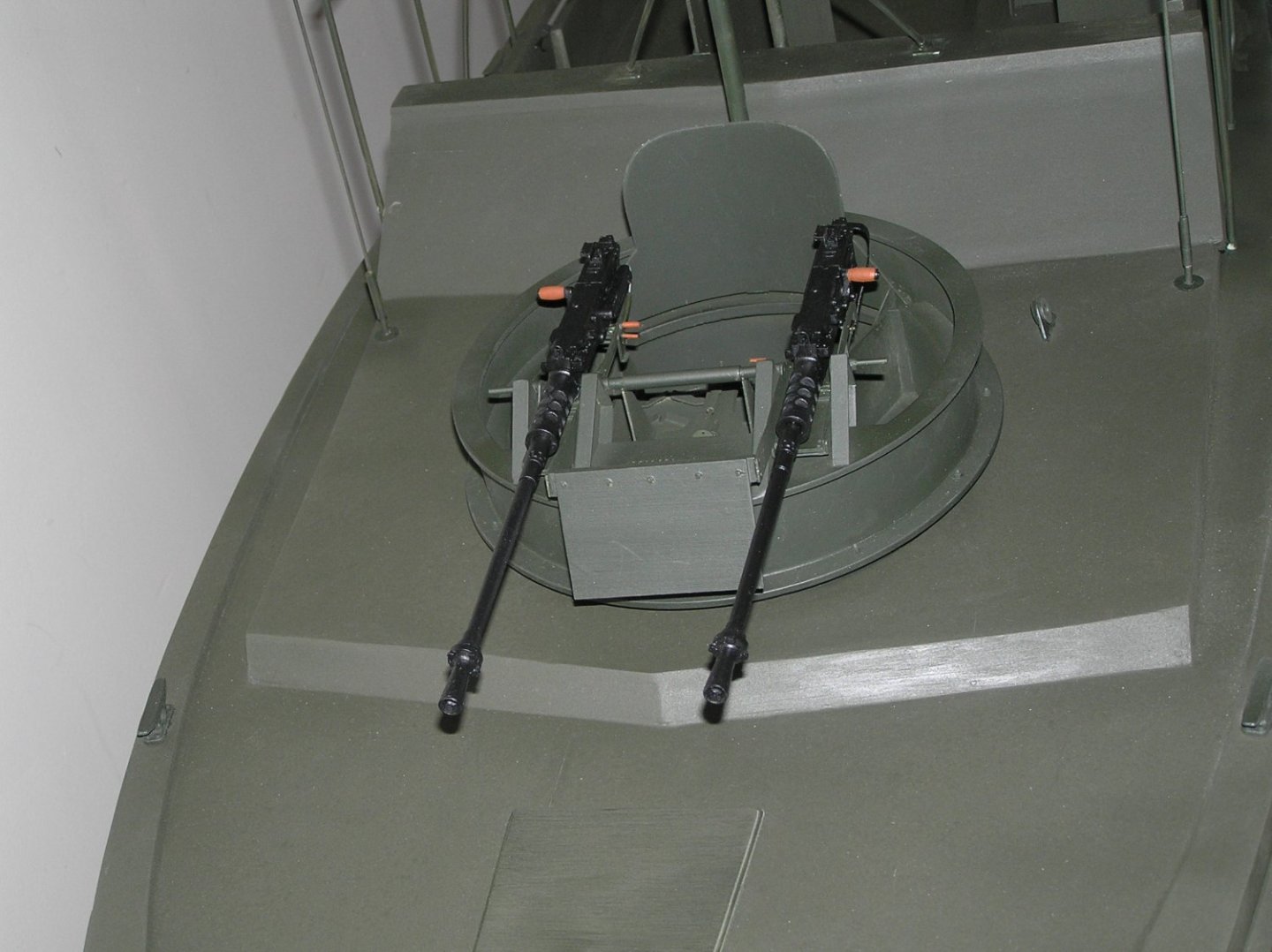
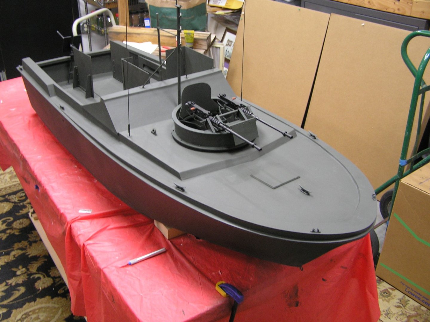
Today was a banner day for the Mark I River Patrol Boat. All the detail and touch was completed save the mounts for the starboard and port guns. This is an easy addition and was taken off line to complete. Note that the canpoy framing has been added. So too with the radar dome, the mast beacon, the rear 50 caliber, boat hook and bilge hand pump. The photos were taken in a hallway as we had to find a suitable backdrop outside the workshop. Doing so does give one the impression it is a small model. I remind all that it is over 5 feet long. A build out discussion will be presented to the group on 1/19 at &PM. It will be streamed so interested parties can message me prior to tune in. Joe
.thumb.JPG.b3fd5f722e0e335b316472aa3828f63d.JPG)
.thumb.JPG.00a3fa5c16af894f6bc3a3797e342c29.JPG)
.thumb.JPG.aa14784af1d0763d5e1f1664d9d0537f.JPG)
.thumb.JPG.e5a25f1e24f0e4962798ee955c770ddc.JPG)
-
Maximizing Model Work Area: Lathe Table
Thistle17 replied to Thistle17's topic in Modeling tools and Workshop Equipment
That can be a problem Keith. I am thinking of puttingup a detachable surround when the lathe configuration is needed. It would be a bit much to bring up the shop vac to deal with the dust. Might even trip my banishment back to the basement if I am not careful. Joe -
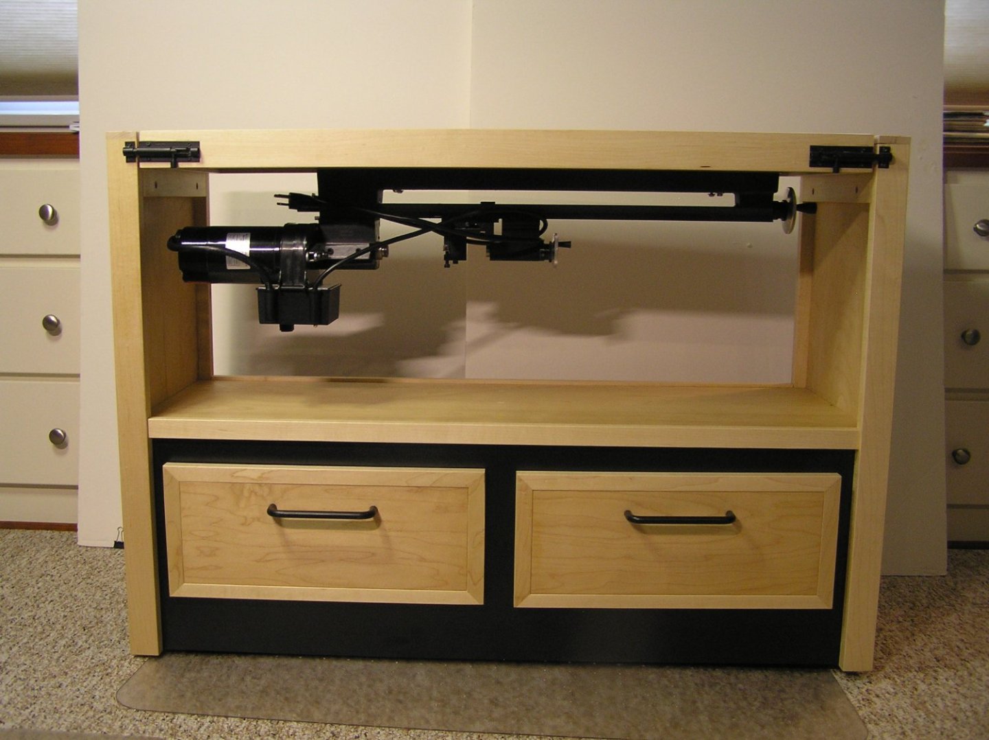
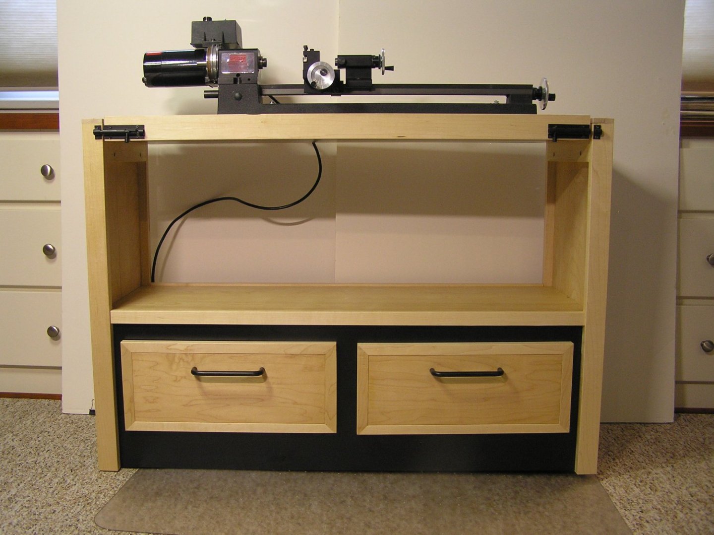
Although I have an adequate woodworking shop I have never thought of it as a model building area, The basement humidity control, lighting, warmth and isolation is too much of a "monastic life" in my way of thinking. So I moved to the first floor in a studio like environment shared by our computer and my wife's art works. The drawback is that the space is not large and keeping it tidy is always a challenge. It became more of a problem when I started Winchelsea. My lathe and mill have been moved to the floor under my desk/workbench when idle. This has been a "get by" solution for about a year. Enclosed are 2 photos of my solution for the lathe that I "stole" from a woodworking shop article I recently came across. Also to build the Winchelsea, which is almost 36 inches in length, I had clamped an extension to my desk area which was an accident waiting to happen. So I merged the 2 thoughts into the solution shown. The cart or table has a flip or pivoting top that will normally be configured as a work table. Bolt latches lock the top in either position. Pivoting the top allows me to use the lathe and "put it away" when not needed. The 2 drawers beneath house all the lathe accessories and also help lower the center of gravity of the assembly when the lathe is upright. When not supporting the model 40% of the unit can tuck under the desk. The whole unit is on casters so it came be easily moved about. The exterior is covered in matte black formica and trimmed in maple. I plan to make a second unit for the mill. Joe
-
Welcome to the party Jim. I believe you will find this project both challenging and rewarding. There are plenty of build logs here to guide you along. I have used a number quite extensively. The key will be to sort out which to follow as there are many good ideas across the board. You have already recognized the ordeal you will have in fairing the plywood you have chosen. yet it can be done with patience and deliberation. I too took an alternate path in the skeletal framing that fundamentally came out well but did have some trip points along the way. I would be glad to share them with you via the off line messaging sytem herein if you wish. Joe
-
Glenn I was struck by your comment about being obsessed with fit. It reminded me of a tour i took some years back of the Stickley furniture manufacturing in Syracuse NY. They make some of the best furniture in the NE. In production of their goods I noticed some pieces being shuttled out of line and put aside. It was related that they did not meet some intermediate requirement. When pressed the tour guide took me over to one of the pieces. He pointed to a joint that was not closed. Yes it was noticable but I could not have gotten a finger nail in that joint. In the finishing area I found a similar piece and there it was being dealt with. The joint was diappearing before my eyes with the deft work of the detailer. The lesson for me was they didn't start over yet the end result was still a beautiful piece. Harder at these diminuitive scales, of course, but the end is still a masterpiece! Joe
- 840 replies
-
- 3
-
-
- winchelsea
- Syren Ship Model Company
- (and 1 more)
-
Getting ever closer to a completed model. The following are back room shots at the museum. At this point most all effort is install of final elements and touch up. The bow shot shows the gun tub in its final home with surrounding detail of antenna, hoist rings, cleats and the like. Signal lights remain to be added. Excuse my out of focus shot of the aft view. It does however show the final install of all armor plate, rear 50 caliber, cleats and a birds eye view of the helm station. Life preserver and boat hook await install. The radar dome will be the last install as we await the erection of the canopy frames which is very delicate work. We will be presenting the wrap up at our January 19th meeting which will be streamed. If anyone is interested in attending please message me as we would be honored with your attendance. Joe

-
I heeded your warning regarding the upper/lowercounter positioning Glenn. Sure enough if I had proceeded with the placement of just the lower counter as I thought correct I would have been off the mark for the upper counter. I have repositioned and dry fitted the lower counter and also dry fitted the transom "skin". I have marked the correct positions and now it is a matter of fine tuning so the upper counter will dock where it is required. Thank you again you are saving me some pain and agony! Joe

-
Just saw your beautiful model on MSW. My, my! beautiful work Jim.
Joe
-
Yes Glenn I suspected this and have dry fitted the placement and even marked the placement on the aft side of the frames at least 3 times. The lower/upper junction intersection is indeed a caution. Moldings can't hide everything. Thank you. I was on the phone with Rustyj yestrerday and he too was quite helpful. I value everyone's advice.!!!! Where else but here could there be such a helpful community!!!!!! Joe


.JPG.a2289845133bf05d661c3726b5022f10.JPG)
.JPG.f54aa243831c2a6f354f8e34bad4bba7.JPG)
.JPG.610109d229e9bfe5b2ba4f6af1fc9756.JPG)
.JPG.1e8475ca5f000d5e240b98260dfd7337.JPG)