Thistle17
-
Posts
1,054 -
Joined
-
Last visited
Content Type
Profiles
Forums
Gallery
Events
Everything posted by Thistle17
-
 Hello Michael. Your disciplined and extremely well executed staging is always an inspiration to me. I think I understand your process well enough as I learned watching David's build of his recent model using similar techniques. The hull blank is in itself well thought out but after trying unsucessfully to blow up your photos, for closer inspection, it leaves me with a couple of questions. Can you relate the following? 1. Is the hull blank a bread and butter fabrication with the extensions for the "ribs" fastened afterwards? 2. Some "ribs" fall within the relief slots and some don't; can you relate what is going on there? 3. And lastly what method did you use to create those reliefs? Thanks Joe
 -
Brass Blackening Building Time Survey
Thistle17 replied to Dave_E's topic in Metal Work, Soldering and Metal Fittings
Just yeaterday I had to replace a chain plate that broke on a restoration I am doing. I followed Roger's method exactly and the results were disappointing. It came out of the solution (JAX Black) quite dark. I placed in a vial of tap water and the blackened surface turned a bit blotchy. Perhaps it reacted with the tap water treatment residuals. I then let it dry and lightly rubbed it with a clean paper towel and all the black came off. What if anything might I change? The solution, move to distilled water...I am at a loss! These results are consistent with other past attempts. Joe -
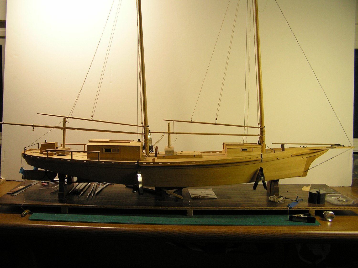
A number of things have kept me away from modeling that I seem to have no control over. However recently I have been able to carve out some time to proceed further with the rigging. This model has some very straight forward rigging and in no way compares to the challenges of say a 5th rate ship of the line. Having said that it certainly continues to present its own subtle resistance to me. Given the age of the model, which is somewhere in the 70 years of age range, is very fragile. Glue joints separate seemingly at will and metal fittings (which are scratch) break at the slightess touch. The other obstacle has been the exquisite execution of the original modeler. I had started out with a conservetorship mentality in the restoration. Having been at it for some time now I realize I was a bit naive! I have been challenged in coming up with like materials in terms of gauge, size and material as the original modeler used a mix of ferrous and non ferrous material. Gaff and boom bands for example were hand made and wrapped around these elements and soldered at some point. The gauge of the metal is less than 0.031! The holes for attachment of hooks or shackles are incredibly minute. In another example, his/her hand made shackles are of size and gauge I just cannot match. I have some (working) ones that broke that are approximately 0.125 in size!!!!! In rigging the model I am convinced that the modeler was interrupted in the process. I say this as some deck furniture was not secured to the deck, and given that some terminations were to the main cabin for example, permanent rigging could not have been accomplished. I also find that some rigging is missing. Missing meaning it was never applied. I have had to consult with Reuel Parker who is a sharpie expert and David Bennett of the NC Maritime Museum to gather enough information to proceed. So with this new found humility I have continued the rigging and have forgiven myself as I find the need to compromise. For example, in the attached picture the main and fore gaff had shackles of the size I described connected to the mid section of each element for hauling. I have reattached them with 'S" hooks in place of shackles. They are carefully "crimped" and in appearance only the most astute eye would recognize this transgression. The rigging is about 70% complete. I had originally intended to add furled sails but have decided against this as I reason there will be an incongruity of that presentation with the base I am making which at this moment will be an "out of the water" depiction. We will see if that is indeed the fianl word. Those vertical posts on the aft end of the main and for boom/gaff setups are temporary rigging aids. Joe
-
Thanks you have been so deliberate about the system setup I guess I just flew by that. Joe
-
Can you remind me please anout the wiring of the limit switches since you moved the controller outside? I don't see the wires coming out or am I missing something? If they are indeed there what connector did you use to bring out the bundle? Thanks Joe
-
Ron you certainly are investing a good deal of thought, time and improvement to this machine. I am sure the lessons learned will be of benefit to many others including myself. And thank you! I have built a number of tool adaptations as well as jigs which I have found for the most part are useful over time for my machines. However the one thing I often wonder and lament during the process is how much time I have spent on it all away from modeling. Now in particular to this project for you I would ask "how will you put it to work"? What usage do you forsee for the sytem in your modeling? It could be a boon to your product for sure. But what do you envision its applications? I ask having had the following experience for an up and coming model I worked with a good friend who has a large CNC system to create my bulkheads and strong back for the project. I will admit getting the end product turned out quite well but getting there was a hill climb. I had a starting point other than a clean sheet design yet the work to make the file(s) ready was a chore. I am not being critical just trying to determine the worth of it all as I think about upgrading from my 3018 Pro to something better such as yours. I would add I am finding the same thing with 3D printing. With my grandson's help we designed a ships wheel using Solidworks. It is a beauty, however when it was sent onto a friend who has a printing system and software it generated so many slices (faces or facets) it was too big for his system. So now I may retreat to milling the components out of brass. You might say I am back to square 1. Do you see what i mean? Regards Joe
-
A "selfie" to go with your good works Ron. Good to see your recent work so well executed. Very nice work indeed. Joe
-
In regard to the ship wheel and the resultant STL file (a 2MB high resolution file) I asked a friend to do a "pre flight" check for me before I sent it off to Shapeways. When it was run through his Slicer program to produce the "g" code it generated 40,000 faces (or slices). It was much too big for his computer to process. So now I have learned another lesson. When you don't know what you don't know you can run aground! At least from a home computer standpoint. I am quickly getting the impression that 3D printing is a bit more complicated than CNC processing where feeds and speeds are the watch word. After discussing the issue it was suggested that the 'productuion' run should be resin as opposed to filament printing. I suspect this will not be a problem with Shapeways as they limit their file size to 64MB or 1 M polygons (I am pretty sure this can be interpreted as faces). Anyone correct me please. Joe
-
Jond i was feeling your frustration in these last updates. Many of us have had to back up and restart. I am still feeling it from a restoration I am doing, I have been trying to diligently replicate the original modeler's techniques and failing miserably. Took several trys to get it! Having said that, your model is a beauty Your persevrance has paid off. Joe
-
Extremely well done and presented I might add! Crisp, crisp, crisp!!!! What is next Ryland? Joe
- 263 replies
-
- 1
-

-
- Medway Longboat
- Syren Ship Model Company
- (and 1 more)
-
In my wailing and nashing of teeth I almost forgot to state some good news. Thanks to my granson home from college and Mahuna modeler of Kathryn a restored skipjack I now have a near ready rendition of a ships wheel designed in Solid Works. One of the greatest elements of Model Ship World beyond inspiration is the willingness to share. Mahuna had gone aboard Kathryn and taken measurements of her wheel (along with her scaled dimensions) and posted that on this site. I had picked a quite similar wheel off the internet. We confered and as a result I now have an STL file for a 3D rendition of my own. Some minor tweaking is needed before submission to a vendor but here was the design process. Joe SOLIDWORKS Shipwheel.pptx
-
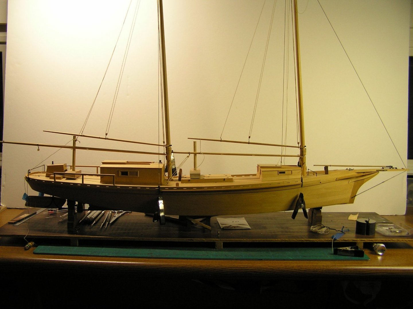
It has been a month since my last post on this restoration. A number of life events have kept me away from the model. Who ever said retirement was a life of bliss!!!! I have to comment on restoration in general. It bears repeating I am no where near an expert at this process but do have basic skills after completeing 5 restorations of lesser models. This model is quite different in that the original modeler was incredibly skilled and made most, if not all, components from scratch. As I have noted I have moved onto the rigging of late and am now working the running rigging. As I proceed I find that his or her ability to fabricate parts humbles me when I try to replace those missing. Schackles for example, of which several are missing, are of such a diminuitive nature are beyond my capability. For example in the preceeding photo one can see an eye bolt on the deck. This is a termination point for a single block that is reeved to a companion block on the fore mast boom iron, starboard side (a similar arrangement is found on the port side). A schackle no bigger than 1/16 of an inch was fabricated out of wire (approximately #32 gauge or smaller) with a clevis simulated from a cut off nail that has a shaft diameter of approximately 0.0125 inches!!!!! My smallest nails are 0.02 inches! In addition, because of age, I continue to find the model quite fragile. Last evening while rigging the fore mast boom port tackle to the helm i leaned a bit too heavily on one of the hatch covers and it collapsed. Luckily repair was easily handled. Just another frustration. What is that saying, "Seemed like a good idea at the time"? Joe
-
After seeing Chuck's work me thinks I should take up knitting or some such past time! Just kidding I guess I will muddle on. Joe
- 1,784 replies
-
- 8
-

-

-
- winchelsea
- Syren Ship Model Company
- (and 1 more)
-
NAIAD 1797 by Bitao - 1:60
Thistle17 replied to Bitao's topic in - Build logs for subjects built 1751 - 1800
Master works bitao! Your joinery is superb. You missed your calling as you should have been a master shipwright. Maybe in your next life???? Joe -
NAIAD 1797 by Bitao - 1:60
Thistle17 replied to Bitao's topic in - Build logs for subjects built 1751 - 1800
An imaginative variation of the machinist 'V" block where the hold down always seems to be in the way. Great design of the clamps. It seems easily transferable to a wooden version for those not into machining non ferrous material. Joe -
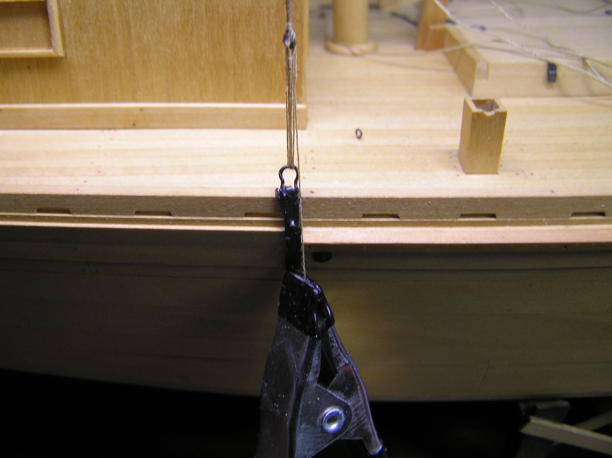
One could have a healthy discussion about the precepts of restoration. When is a replacement part, made anew, but differently, yet retaining the functionaly to be considered an unfaithful reproduction. Well call it what you wish. I had to scrap the replacement chainplates. During install they were so delicate that the tip which was a piece of soldered tubing attached to the plate body separated in both accounts. The stress was just too great on this diminuitive part (just about 1mm). I had to remake them much as I and others made Cheerful chainplates. You can find this in Chapter 9 of the Cheerful build log. Basically the chain plate has a tang at its top that is bent into a loop that allows connection of the lower deadeye to the chain plate. In this model there are no deadeyes. There is a looped line that passes through a shackle attached to the formed eye of the bent over tang on the chain plate and the shroud eye to adjust tension. Attached photo is the reconstructed chain plate with shroud lashing installed but not tied off. Tie off is identical to deadeyes. It is no wonder why they were missing on the model when I got it. I will move on from here and not look back. Joe

-
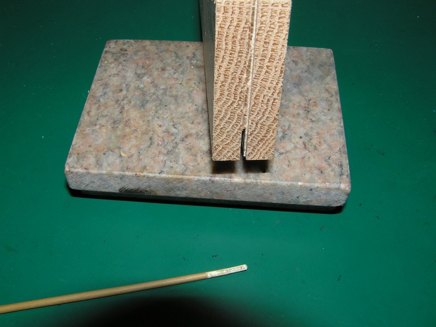
Preparations to repair the rigging have gone a bit slower than anticipated. I finally gave up trying to repair the broken brass chain plates that were on the model. Curiously the builder had decided to make them in 3 parts; a lower section connected to the hull, a mid section that was bent and soldered to sit vertical and the schackle like shroud tether. Between alignment problems and poor solder joints (even after cleaning and tinning they would not hold) I gave up and started anew. The remade versions were one piece straps of 3/32 X 1/32 brass strip bent to the correct angle. The chain plates were fashioned with a narrow tang at the top similar to Cheerful's chain plates. I must be losing it here is an [EDIT]I am working on 2 models at once, Cheerful and the Sharpie. The Sharpie chain plates were made differently on the original model. A brass strip was made of the dimensions stated and tapered a bit at the top. Atop the narrow end a small brass tubing of 1mm was soldered. To this new pre-formed shackles were attached. They were made this way to faithfully reproduce the original modelers intent. They are much harder to make however.These only need blackening to complete the process. Now the club foot boom termination on the "car" or traveler for the jib was a different story. The model as received was missing the metal work and until I received help from Reuel Parker's article in Professional Boat Builder I was at a loss to come up with a design. In the PDF above, on page 54, figure 3, is what I needed to recreate the element. I tried twice to make the forward metal work but each time the results were either only partial fufilment or were unacceptable product. On the third try I decided to try a different approach. Starting with some 2mm square brass tubing cut to length to include the forward yoke to attach to the car and long enough to simulate the boom strapping. The yoke holes were then drilled. From earlier experience I knew any files I had were too thick to fashion the yoke ears by removing the top and bottom walls of the tubing so I turned to my Byrnes saw knowing the 0.030 slitting blade could cut through the brass. Holding the piece safely was the problem. Shown in the photo below I cut a narrow slit in a piece of hardwood, trial fitting as I went and flipping the face against the fence for an exact centerline cut. I stopped when I had a strong press fit of the 2mm brass tubing within the slit. It then became a simple matter of moving the fence gradually and subsequently flipping the craddle face against the fence to cut the desired openings. A small section of the piece was left solid on all faces to maintain structural continuity. In turn the boom was shaved slightly to accomadate the newly formed simulated straps. The product is shown below the holding block. What remains is the "in haul" metal work to complete the final missing rigging elements. I don't want to admit to the number of hours it took to get to this point. Joe
-
Just my two cents here. I tried to improve production on Cheerful by ganging them (4 at atime). Not a good idea as the char and bevel make it difficult to get it done to satisfaction. Removing the char well and getting consistent diameters was the challenge. Rusty you are back at it with a vengence. Wonderful work. Would like to have you featured in January or february if not in person with some of the photos that cover technique. lets talk. Joe
- 642 replies
-
- 3
-
-
- winchelsea
- Syren Ship Model Company
- (and 1 more)
-
David the Zoom coverage of your model was so lacking (not anyone's fault, just the nature of remote viewing) at the HRSMS that it did not do your model justice. In terms of fittings, the Florida Sharpie has minimal fittings as i suspect the real craft did, given they were built in "back yards". My sharpie has 4 open chocks at the bow/stern for mooring, two bowsprit cheek mounted blocks for anchor operation and nothing else. The tack rigging is all deck mounted blocks. The rudder is in an aft wheelhouse so not much external there to speak of. Cleats are all located on the main cabin as the helm controlling all but the jib. If that helps. Joe
-
I will give your suggestion a try Ron. Thanks. Joe
-
This discussion of a new and more ambitious project seems to be creating quite a stir. Surely there is need for a vaccine or pill to slow what appears to be another spread of unbounded enthusiam or a closet of unfinshed models! Present company included. We are all hopeless!!!! Joe
- 1,784 replies
-
- 5
-
-
- winchelsea
- Syren Ship Model Company
- (and 1 more)
-
Another example of running a full sytem check of function before the product goes out the door. You just solved why my system overode my DIY limit switches. Thank you Ron. Joe
-
I ran into a set of mechanical and software problems with my 3018 Pro. Not sure this isn't normal for everyone. For a seemingly well made, reasonablly priced unit it does make one wonder how much testing these products have had prior to the mnarketplace. Nonetheless Ron your journey is packed with good information and should be helpful to those that follow. Thank you for posting. Joe
-
The kind and supportive editor at Professional Boat Builer sent me a reprint of the Parker article in the June/July issue of 2021 that fully describes the bowsprit rigging and rationale for club foot booms and "cars" or travelers. It even gives more detail on page 54 of just how this area of the boom should be rigged. I have already made the "business end" of the club foot boom but am now considering a 3rd redo to more accurately reflect this new data. The editor of Professional Boat Builder has graciously granted permission to include Reuel Parker's comprehensive article. There is a wealth of information within. As I reflect on my pursuit of the sharpie history and its characteristics my respect for this vessel continuses to grow. I also have to acknowledge the people who build, restore, preserve and document the real craft.. Without them this information may forever be lost. Joe Bowsprits191-FINAL.pdf
-
I see reference to starting Chapter 10 in Chuck's build. Is Chapter 9 the stove build or do we await it's release? Joe