Thistle17
-
Posts
1,054 -
Joined
-
Last visited
Content Type
Profiles
Forums
Gallery
Events
Everything posted by Thistle17
-
 I am taking your advice Glenn and began the process of planking the lower counter. As I approached strake #5, in a dry fit mode, I encountered a bit of interference with the stern post. I have checked and checked every aspect of the stern framing and the remade frames A and B. They are pretty much on. Rather than fight this I have decided to premark the stern post cutout at this stage and "prep" this area for removal while on the bench. I Have also included the relief in stake #5 to get around the interference problem. I will allow some tune up real estate once that stage is reached on the model. It isn't that long ago that I remember my difficulty with Cheerful's stern post relief so I have to assume in the long run I will be more satisfied with the outcome. Joe
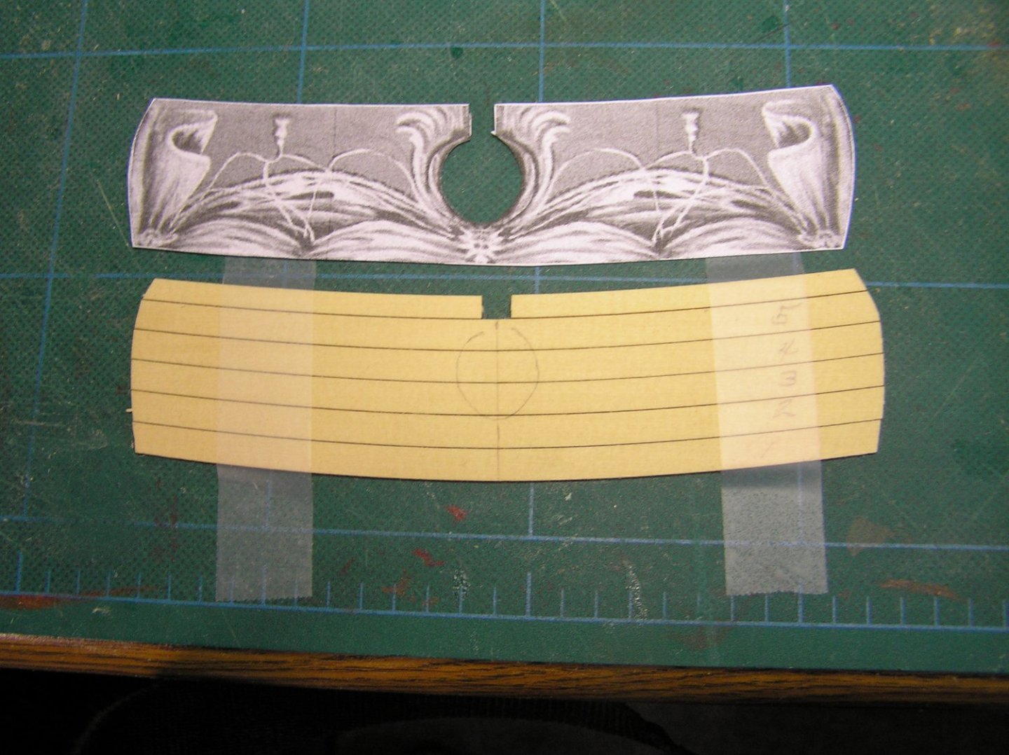
-
Thanks for the coaching Glenn. I have hesitated on the counter planking but will do so now.Your postings is one I follow closely. Your progress is amazing. I have to develop some rythm for my build. The stop, start method I seem to be in just makes the build more arduous. I am not sure I mentioned it before but I worked in Dallas for a year back in 1973 - 1974 on Mockingbird Lane at the corner of I35. Lived in Denton. That was a 32 mile trek to and fro on I35. It was crazy then has to be a white knuckle drive now I would imagine. Joe
-
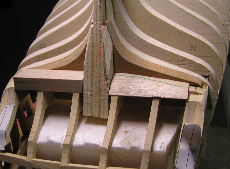
Glenn I wish I were at the planking stage. It has been one interruption after another mostly family needs. I did finish and deliver a display table to my daughter and am wrapping up a portable stand for my Sherline lathe ( I will debut it a bit later). As I work in our study/computer area I have to constantly work to keep the area clean. In addition Winchelsea is so big I have had to come up with a temporary" work bench extension". The lathe stand will help solve that problem as it can support the model when not serving the lathe. So Winchelsea has suffered. As witnessed by this post where I am asking for a little guidance. I have been fairing the stern area after "plinking away" on the gun port framing. I have used a number of MSW builder references including Chuck's postings for stern faiting. To me it seems a bit subjective as to how to achieve the desired end point.The attached picture (with mark ups) shows my progress on this critical area. I have rough formed one of the fillers that will "land" the planking for the port side. Using fairing strips it appears close to the correct taper torward the stern but still needs tapering towards the port side. I have crudely marked that area in green. Secondly the stern post area still appears to need contouring all the way down (up) to the filler. This suggests that frames 29, 28 and 27 need much more sanding to an even more wine glass contour. Am I correct here? And lastly it appears the bottom side of frames C and D need little to no tapering towards the stern save for the side. That appears to need some build back. Again am I correct? Joe
-
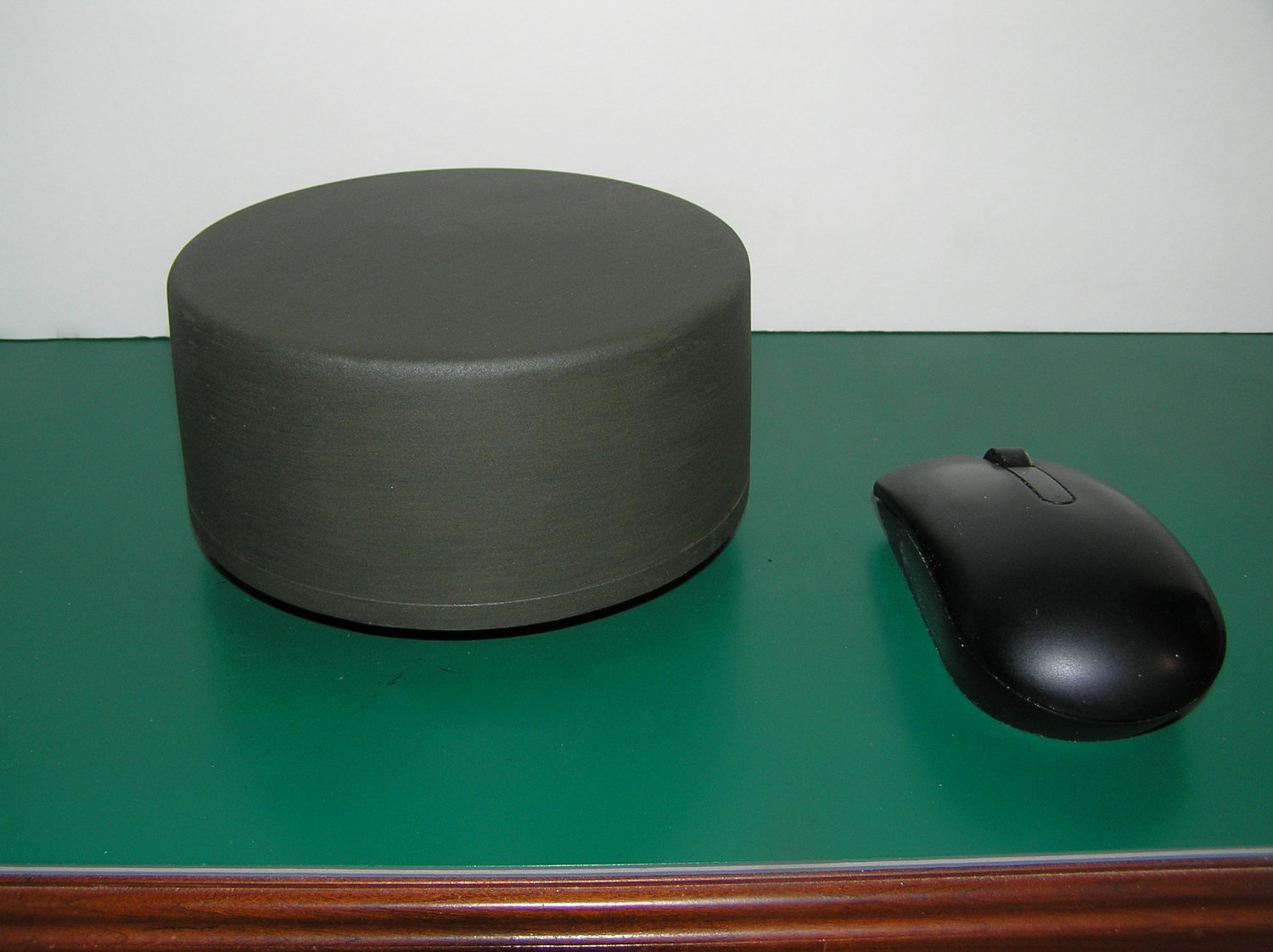
Just a brief update on our trek to completion of this waterline model. Amongst many elements of detail to be added to the model this is one of the final ones. The radar dome is 5.5 inches in diameter and3 inches tall. It was turned on a large lathe as it was too big for my Sherline. Even though it was hollowed out of basswood save for a hub it still weighs about 0.7 pounds. It will be the last thing mounted given its properties. In the catergory of "I should have known better". The basswood was in my basement shop trove for some 10 years at a humidity level of around 50%. The completed dome was brought to the musuem workshop and over 2 weeks shrunk given the quite low RH there. The banding around the base was wrapped and glued 0.20 AYC (cedar). The effect as you might expect was a warped band. The only practical solution was to wrap the lower base in an automotive tape and paint over the entire assembly. It now sits in a sealed plastic bag awaiting final install. Here's hoping! Joe

-
You are gifted Rusty! Your work always amazes me! Your photos along with others on this site, not only are of an instrcuctional nature to me they are truly inspirational. Joe
- 642 replies
-
- 4
-

-
- winchelsea
- Syren Ship Model Company
- (and 1 more)
-
Amazing you have turned this into a beautiful model. Looking back at your start photo I just realized that is the same kit I bought in the 1980s at Bliss Marine in the Boston area. If I remeber it was on sale for around $90 US as it had a broken but repairable "keel". I started it but never got far as I got distracted. Not only is your work excellent I have to applaud your tenacity! Joe
-
Greetings to you as well. I hope you find this site as enriching as many of us have. It is a treasure trove of information on many aspects of this pursuit. I have also found that the more I have used it, the more I have had personal contatct with some remarkable people who are willing to share. Joe
-
A fine modeler was one of his talents. A kind, supportive, sharing person were among the qualities he revealed to me. My condolences to his family and friends who had the good fortune to be in his life. Joe
-
Thanks Mike I will take the added step. And Rusty I took a look at my Cheerful again this AM and three of the starboard planks which were a tad dark seemed to have darkened even more.The model is now about 3 years old. Port display appears to be in order. Will the perfect model ever be in my reach????? Joe
- 642 replies
-
- 2
-
-
- winchelsea
- Syren Ship Model Company
- (and 1 more)
-
In touring the Stickley furniture factory, sometime back, it was related that in the finishing stage they apply a translucent base (in the case I saw it was on the order of an orange color on cherry). This tended to "flatten" the color variation across the surface. This can even be evident in the boards of the same tree. I am keeping my ripped AYC for planking from the same blank together to minimize the problem. It was evident on my Cheerful. But I am sure you folk know that. The "wetting" method given is indeed a good idea. Joe
- 642 replies
-
- 1
-
-
- winchelsea
- Syren Ship Model Company
- (and 1 more)
-
Brad I started with a scratch built hull (bulkheads, false keel or strongback etc.). Even though they were accurately machined using a CAD/CAM approach they have given me some grief. In part because of the inferior plywood I purchased. At this point I have completed the port gun ports, installed my second transom assembly and partially installed the starboard gun ports. I have expended too much energy and time to get to this point. Were I to do this again I would have thought better of starting from the point I did! This is an extremely well designed kit and would have been much easier had I started from the intended point. I have built other models from Syren. Just a caution. Joe
-
Ab I cannot wrap my head around the fact that this endeavor was done just for fun. The skill, depictions and execution are just stunning! The works of countrymen artists such as Vermeer and others always give me pause. And I have to say so too does this work! Joe
-
Ok Glenn I am sending mine onto you as you have the method down perfecrly!!!! Joe
- 840 replies
-
- 3
-
-

-
- winchelsea
- Syren Ship Model Company
- (and 1 more)
-
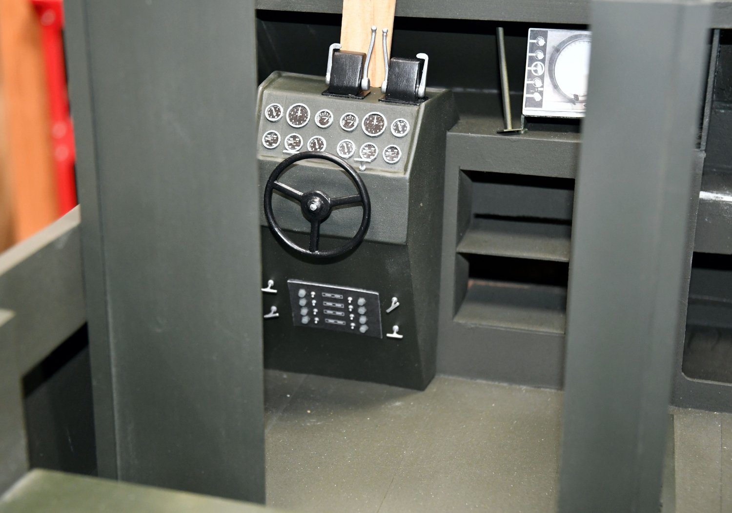
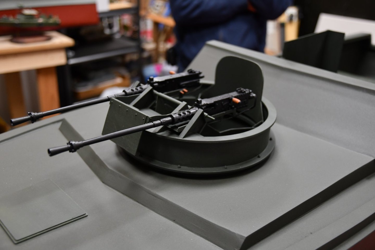
Now that the model has been moved back to the museum it is receiving the attention it deserves. The director of the museum supported the effort by purchasing an airless paint gun with adjustable nozzle patterns. Since the hull had more than enough time to cure the oil thinner" based paint it was decided to spray the hull with latex. I must say it was a hugh improvement over the earlier attempt. Chuck, the director was able to keep a wet coat and as noted the results were quite pleasing. After months, no years, of a bare hull we could not resist dry fitting some of the major components to give ourselves a boost to "bring the project home". Shown in the accompanying photos we temporarily placed the pilot console and the armament sheilds in the helm area. And of course we had to witness the forward gun tub resting in the hull. Also note the venturi is now in place and some of the helm area braces (not shown) have been added. It is amazing how even the little things contribute to the character of the project. Standby as we will be installing signal and radar masts, attennas, aft gun platform, canopy framing and all the other previously mentioned elements. Joe

-
A masterwork! I was fascinated with the hull construction. The "plating" was just beautiful. Such an interesting subject as well. Joe
-
I have tracked your work since I discovered this site some years ago. Your work is always inspiring. As the saying goes "love like youth is wasted on the young". One might draw a comparison to ship modeling and modelers. General health including sight, dexterity and the like, most needed for modeling alude us as we age and when we are most apt to be into this pursuit! Wishing you a speedy recovery. Be patient with it. Joe
-
After nearly two years in my basement and garage the hull for the PBR has gone back to the museum for final detailing. It is a mixed milepost. The venturi or cowling in the helm area was installed and glassed in for a finished look. The whole area was primed and painted. Unfortunately we used spray cans of the paint, a flat enamal. Unfortunately the spray pattern was too narrow and it was almost impossible to get a full wet coat. Quite disappointing after all the work we put into the glassing , glazing and fairing of the hull. A quick stop on the way back to the museum at an auto body shop for a quote was disappointing. The owner quoted an $800 charge!!!!!! Looks like we are going to break out some home gear to have a go at a final wet sand and repaint. Very few deck appointments need to be completed. All cleats, armor shields, canopy frames, masts, helm, radios, scope and of course the forward gun tub and aft gun are ready to install. We just have to get past this hull paint situation. Who knew this journey would be so troubled. Joe
-
Such a rich, warm effect achieved with the wood choice and color added. Joe
- 642 replies
-
- 2
-
-
- winchelsea
- Syren Ship Model Company
- (and 1 more)
-
As they say Glenn copying or following another's work is well deserved flattery. Your work is in my list of one's to follow! Joe
- 840 replies
-
- 5
-
-
- winchelsea
- Syren Ship Model Company
- (and 1 more)
-
A guide to using MSW
Thistle17 replied to James H's topic in Using the MSW forum - **NO MODELING CONTENT IN THIS SUB-FORUM**
Wonder of all wonders. Using the Google Reset function worked this AM. Resetting each element, cache, cookies, history independently did not do it. Thank you Mark! JOE -
A guide to using MSW
Thistle17 replied to James H's topic in Using the MSW forum - **NO MODELING CONTENT IN THIS SUB-FORUM**
Well, it appears that while I was away and using my laptop I used another browser. That browser automatically admits me. I tried clearing its cache, cookies and site preferences to no avail as Google Search still requires me to log in. I will continue to work it. Joe -
A guide to using MSW
Thistle17 replied to James H's topic in Using the MSW forum - **NO MODELING CONTENT IN THIS SUB-FORUM**
Hmmm! Tried this 2X and it did not work. Any other suggestions. Could it be it still recognizes my laptop id? Joe -
A guide to using MSW
Thistle17 replied to James H's topic in Using the MSW forum - **NO MODELING CONTENT IN THIS SUB-FORUM**
James I have been a member for over 5 years but seem to have to sign in each time I enter the web site inspite of clicking the "Remeber Me" selection. This is new after I returned from a trip last week where I used my laptop rather than my desktop which is the most frequently used device. Joe