Thistle17
-
Posts
1,054 -
Joined
-
Last visited
Content Type
Profiles
Forums
Gallery
Events
Everything posted by Thistle17
-
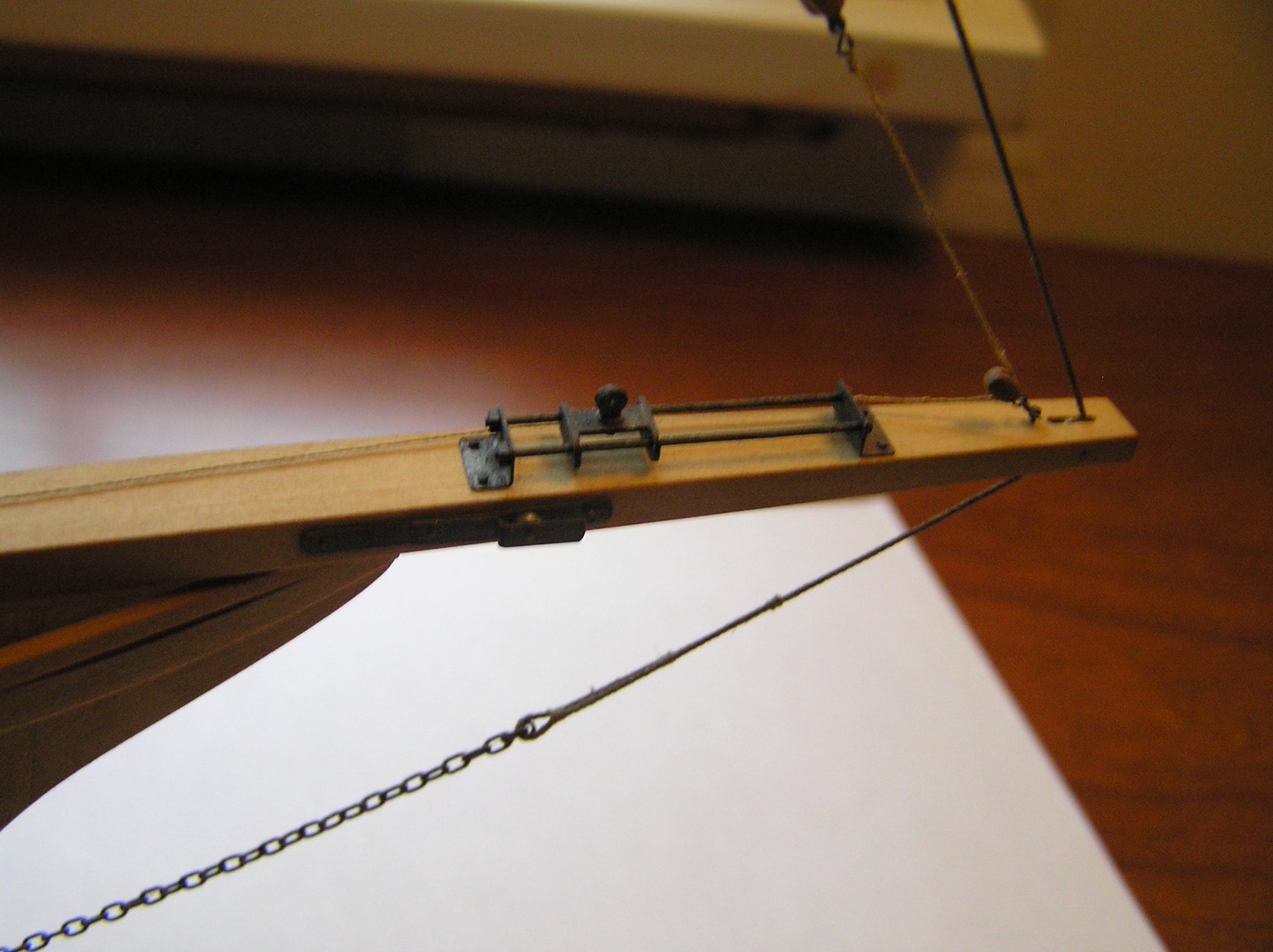
 With Roger's added reference of the book, The Sharpie Book, by Reuel Parker, I now have a much better understanding of the rigging of this vessel. I repeat the quote from an email I received from Reuel Parker here about the bow sprit rigging which was most puzzling to me until his revelations: [The forestay rove through a sheave in the bowsprit is a typical Chesapeake Bay arrangement, but there is usually an outer forestay with conventional bobstay beyond the inner forestay, whose function is to support the mast and carry a “spectacle iron” from which lazy jacks are suspended to contain the club foot boom and furled jib. This is absent here, so there is only the single forestay. The “car” on top of the bowsprit allows tensioning and releasing the club foot jib boom, which is absent in the photo. The car arrangement was commonly used on schooners. The inhaul lanyard is missing, but the outhaul lanyard is in place. There is a gooseneck on top of the car for the missing boom. The traveler on deck is for the jib sheet, which would be attached to the aft end of the club foot jib boom; the block at the front of the mast is for a fairlead for the jib sheet. The cheek blocks on each side of the bowsprit are anchor rollers. You might refer to Chapelle’s “American Small Sailing Craft” and his booklet on Skipjacks for further information. Or my article in Professional Boatbuilder Magazine last summer on Bowsprits.] In his book he also describes on pages 143 and 144 the "car" or traveler arrangement for a San Juan 36 foot Sharpie. the only difference here is that the club or boom is 'fairlead back to the cockpit coaming for control by the helm. This would be difficult on the Florida Sharpie as the deck would have been laden with catch making the fairlead difficult to control I suspect. So the picture has indeed opened up. As I suspected the cheek blocks have nothing to do with the "car" or traveler. So that is no longer a point of confusion. Further I have to consider his advice on the fore stay comments and the missing irons. I have contacted Wooden Boat to get a reprint of the article he suggests and should be getting that soon.
 -
Florida Sharpie Fore Stay Sail Rigging
Thistle17 replied to Thistle17's topic in Masting, rigging and sails
Well Roger the "bread crumb" trail has opened up a bit. After I received Parker's book I rapidly read sections that might pertain to the information I was wanting. The detail was not there but the next best thing was; a way to contact Reuel Parker! Amazingly he responded yesterday and provided me the following information. I quote his response: [The forestay rove through a sheave in the bowsprit is a typical Chesapeake Bay arrangement, but there is usually an outer forestay with conventional bobstay beyond the inner forestay, whose function is to support the mast and carry a “spectacle iron” from which lazy jacks are suspended to contain the club foot boom and furled jib. This is absent here, so there is only the single forestay. The “car” on top of the bowsprit allows tensioning and releasing the club foot jib boom, which is absent in the photo. The car arrangement was commonly used on schooners. The inhaul lanyard is missing, but the outhaul lanyard is in place. There is a gooseneck on top of the car for the missing boom. The traveler on deck is for the jib sheet, which would be attached to the aft end of the club foot jib boom; the block at the front of the mast is for a fairlead for the jib sheet. The cheek blocks on each side of the bowsprit are anchor rollers. You might refer to Chapelle’s “American Small Sailing craft” and his booklet on Skipjacks for further information. Or my article in Professional Boatbuilder Magazine last summer on Bowsprits.} So the picture begins to open up. As I suspected the cheek blocks have nothing to do with the "car" or traveler. So that is no longer a point of confusion. Further I have to consider his advice on the fore stay comments and the missing irons. I have contacted Wooden Boat to get a reprint of the article he suggests. So bit by bit the rigging becomes clearer. Thank you again for the leads. Could not have done it without your help. Joe -
Florida Sharpie Fore Stay Sail Rigging
Thistle17 replied to Thistle17's topic in Masting, rigging and sails
Roger you always come through. Simply amazing! You are such a wealth of scholarly information and help. I ended up ordering the book after reading the reviews on Amazon. Why this item never popped up in my internet search I suspect is that I got too specific about what I was searching for. In the interim I did find how the boom was attached to the traveler. What threw me off was remnants of some metal work attached to the traveller eye. That coupled with the fact that the boom forward end was missing a mating piece left me wanting. I am hoping the book will give me further insight into those two pulley elements attached to the starboard and port sides of the bow sprit as their current position (which matches the Chapelle drawing) doesn't seem to allow forward and aft movement of the traveler without some other termination points for necessary block and tackles. Also, as there are no other termination points on the traveler itself, nor any boom collars depicted that might serve as "hauling" points I still am a bit puzzeled how that all works. I am hoping the book helps. It occurs to me that people are wondering about my "reverence" for this model and my deliberate approach to its restoration. I sometimes wonder myself! It starts with my admiration for the original builder. His workmanship, as I have related, is superb and his product is quite faithful to the drawing. I just feel a strong need to honor his work and be as diligent as I possibly can. Joe -
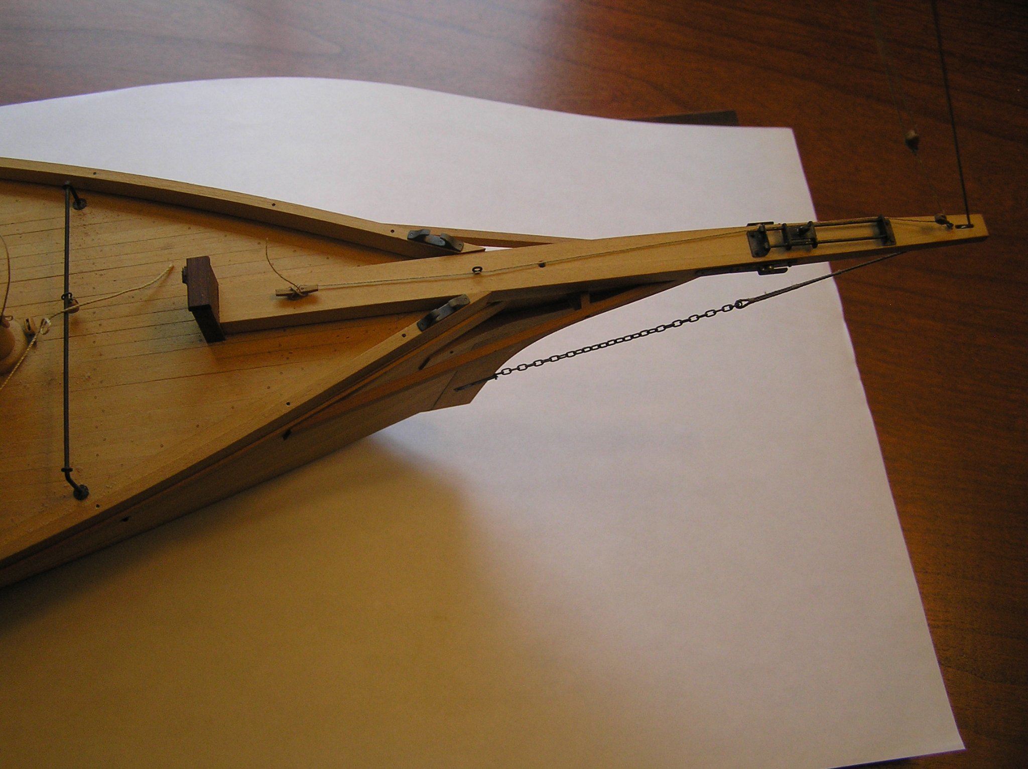
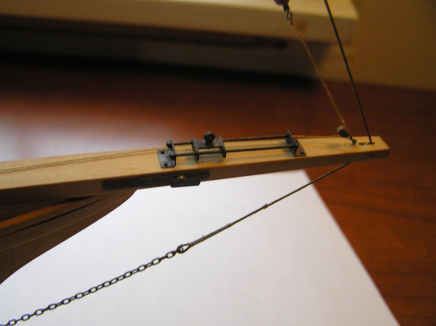
In the restoration of this rather exquiste model of a Florida Shapie Fishing Boat which is posted within this forum I have come to a point where I find I am lacking enough information to complete the bow area rigging. David Bennett (NC Maritime Museum) has been very helpful in supplying information for the main and fore rigging but since this area is unique I am asking for help. The first picture I have included shows the bow sprit traveler for the fore stay sail. Note it does not show any evidence of a fore stay shourd forward of the traveler and it seems that the bow shourd is too far forward. There is a fore stay boom (not shown) and its length is just right to fit the distance between this traveler and the tacking traveler aft (second picture). There is a halyard at the very tip of the bow sprit but seems too far away from the traveler to be of use. My questions are: 1. How was the sail boom attached to the traveler?, 2. There seems to be no way to draw the traveler carriage fore or aft as there are no "tie off points" evident., 3. How are the bow sprit side tackles employed in the rigging? Would be most appreciative of any feedback. Joe

-
Welcome Jorge! Please take a look at your fellow countryman's work and web site. He is a distant member of our group (Model Shipwrights Western NY) in the US. He is a professional modeler of the highest nature. He lives in Lisbon. Joe Carlos Montalvão: Personal curriculum vitae (résumé) (carlosmontalvao-curriculo.blogspot.com) his bio Carlos Montalvão - Museum standard ship models (carlosmontalvao.blogspot.com) His web site
-
John just tuned into your work and methodology. Certainly something to admire and I am always learning from others. Your application of technology, as subtile as it is was, an eye opener. Joe
-
Alan these tools in some respects cost more than my full sized versions which date back to the 1990s. As David says I never looked back they are a joy to use and quite frankly are priceless! Saw dust on!!! Joe
-
Ron this appears to be a much improved version of "front end" capability. It also looks like your off to a much better start up than I had experienced. Npw the G Code Sender, UGS is that free ware? Joe
-
Chuck if you tap into the Lee Valley web site you will find a trove of information on tool sharpening. Joe
- 1,784 replies
-
- 5
-

-
- winchelsea
- Syren Ship Model Company
- (and 1 more)
-
Ron this is a much improved unit over the 3018 Pro which I have. My one word of caution is the software they supply in their package. Unless they have in like worked on it there will be an uphill learning stage. I will be anxious to follow your "power up" reporting. I could not even run the test programs until I discovered that the Y axis direction needed to be reversed in the on board NVM. It was only after exploring the internet did I find what all the parameters were. One reversed the direction but there were others of the same ilk. Once found however the parameters are a bit obscure in definition so be very careful should you need to change any. I don't know if you are planning on using their CAM program or something more elegant. If you haven't played with the INVENTABLES "CAM" like program you will see what I mean. Actually it helped me discover the NVM error in the Arduino control system. I will be a follower of your travels and likely learn from your experience. Good luck! Joe
-
Be honest now...when did you sleep? Joe
- 274 replies
-
- 1
-
-
- Cheerful
- Syren Ship Model Company
- (and 1 more)
-
This project gets more and more enchanting with each new step. Truely a marvel in design, production and execution! I might add that your employment of modern technology in laser and cnc machining seems to have no bounds. What could be next???? Joe
- 1,784 replies
-
- 2
-
-
- winchelsea
- Syren Ship Model Company
- (and 1 more)
-
I received the book via Amazon in 2 days! It is a superb volume! Joe
-
You have a gift Ryland. Another beautiful model coming to life. Joe
-
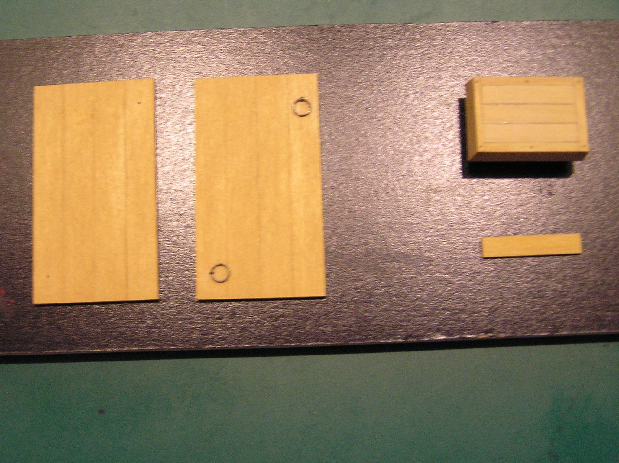
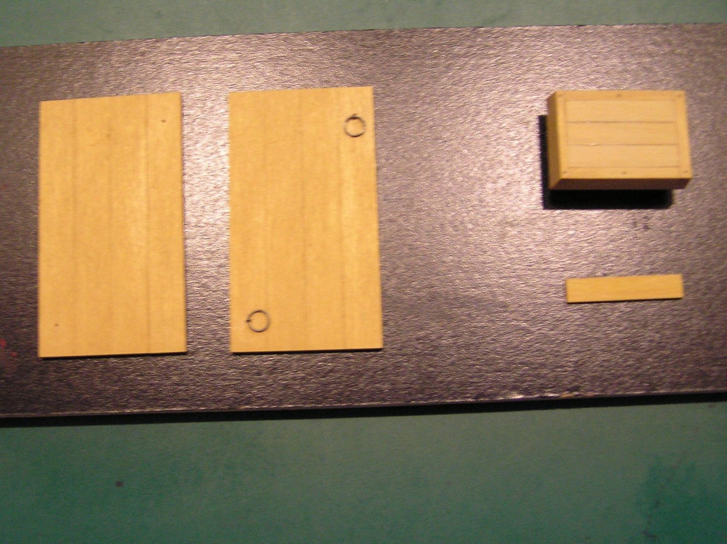
If it seems I am obsessing over the restorartion of this model it is most likely true. I have such respect for the creator's craftmanship that I feel if I do not try to replicate his work I am doing the person a misservice. There are some wooden parts missing. Namely the port engine hatch and the main cabin doors. given the patina of the aged wood I have been experimenting with different species to see if I can approach existing wood aging. I happen to have a sheet of Alaskan Yellow Cedar that is actually on the orange side. I had to mill it to .039 in so I lost some of the color but my first coat of WOP seems to be bringing in the correct hue. A few more coats should do it. To the upper right is the hatch. I have built the lid and it is yet to be finished. I show it as further testament to the creator's talent. Observe the "tree nailed" framework of the assembly. This person even treated the inner sleeve that sets down in the hull (of course nobody can see it) with the same detail and the same precision. To the left are the main hatches for color comparison. Joe
-
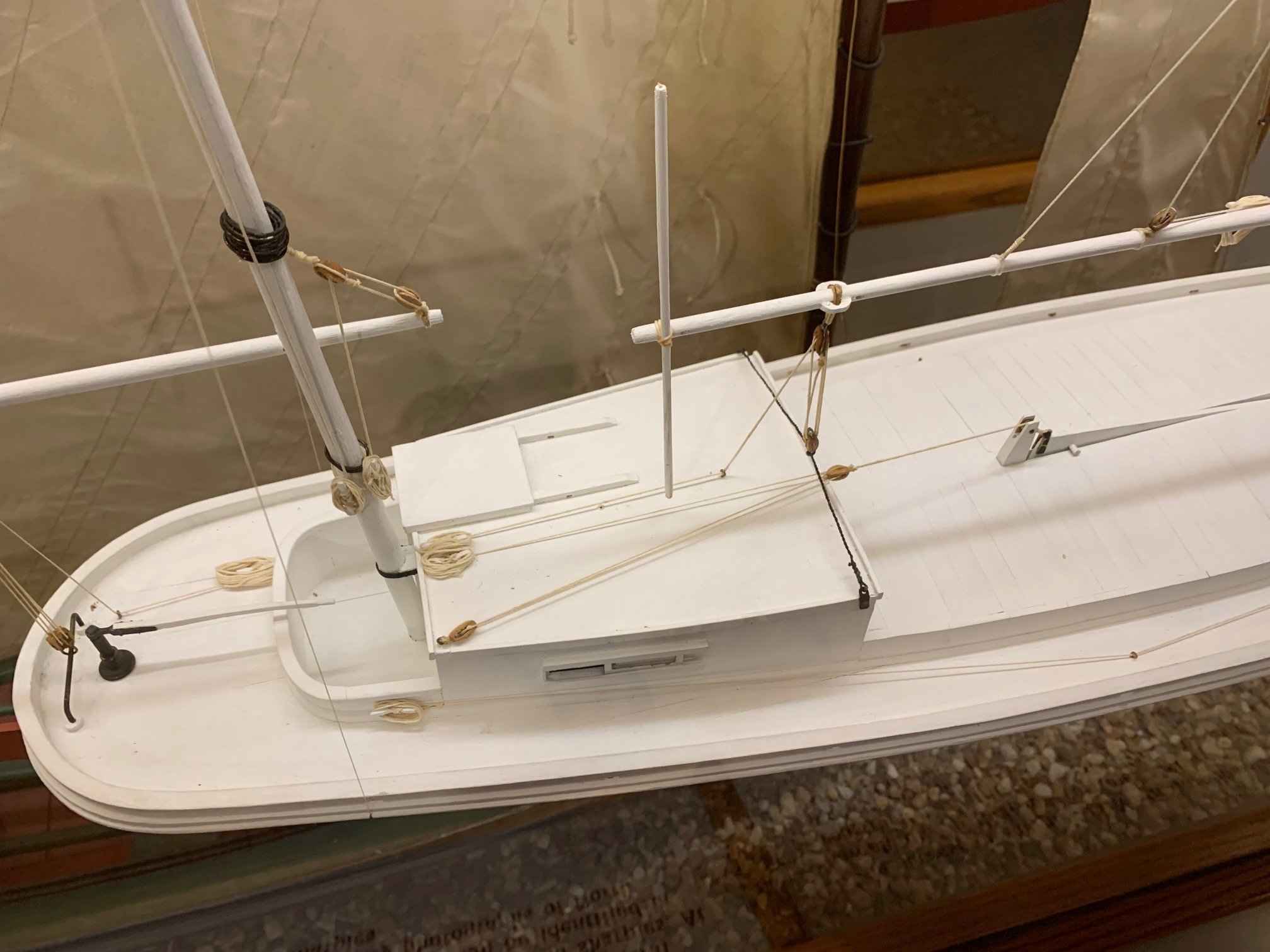
I know I have intimated this before but each time I approach this model to evaluate any restoration element I find myself in awe of the original builder. Everything on the model is of the highest precision and execution. Planking, deck furniture, metal work replication is just astounding. Each tree nail, each pinning is precisely located. In evaluating building a missing hatch in the stern I now realize the entire hull has been ribbed and I will bet all bulkheads called out on the drawing are there as well. I can not imagine that this could have been done without machinery. In examing the hatches and the deckhouses I recently discovered the modeler had used quarter sawn material to minimize expansion problems. I am still a bit puzzeled as to the wood species. The model has never been sealed so there are years of a deep patinia to the wood. At times I suspect it is boxwood due to its density (using the finger nail depression test) or bass wood that has just dried out over time. When I look at the end grain of the items I mention I can see a distinct grain so it makes me think I still do not know. As an aside I was trimming a flowering ornamental apple tree today and in examining the grain and color it made me think it just might be hand milled lumber of this sort. Now the other aspects of this model are its origin and its travels. It has had some disrespect in that some boom and other metal work is missing, there are missing doors to the main cabin, some rigging is missing on both the fore and main sails, and oddly some key deck terminations for fore and main sail control from the stern were never added. There is more but these are the main elements. So one question, that I probably never will answer was why wasn't she completed? Perhaps it was a life interrupted and then perhaps it was something less tragic. On another note the modeler had such an intimate knowledge of how it was built and rigged even in areas where elements are not shown in detail or below deck. One source could have been the North Carolina Sharpies as they were so close to this Florida Sharpie. But they were virtually wiped out in a hurricane somewhere in the mid 1930s. Could the model be even older than I think???? An update: I forgot to mention that all sheaves are boxwood, fully operational with what appears to be aluminnum or iron innards. They too are incredible. At this point I have to live with the unkowns and drive forward hoping that I am worthy of restoring this incredible work. Stay tuned if you wish. Hopefully next time there will be more show than tell. Joe
-
Obviously this is not your "first rodeo". Excellent work and incredible drive moving to the finish line! Joe
- 274 replies
-
- 3
-
-
- Cheerful
- Syren Ship Model Company
- (and 1 more)
-
Hey Chuck was just looking at your blocks and trying to figure out your process. If you recll you gave me the Winne "laser" files to create my own bulkheads and strongback with a CNC. Indeed it was a learning experience! Yours It would seem to me would be executable with an X, Y, Z axis cnc but would benefit with the 4th axis of rotation. You don't have to spill the beans but is that how you pulled these off?
Joe
-
As you intimate I wasn't happy with the transom at first encounter either. But now with the paint detail you have applied I have to say I am taking on a different sense of it. Thank you. Joe
-
Nice work harlequin! My Unicorn, a 1980's kit is sitting in a container maybe never to finish as the materials then were quite second rate by some standards. Maybe, just maybe you can inspire a restart for me with your good works. Joe
-
Incredible, this world technology we so often take for granted and that is so abused by many I might add! Within minutes this morning David Bennett of the North Carolina Maritime Museum responded to my email. He is the curator there and is extremely knowledgable on the sharpie's. He sent me several photos that answer the question clearly, I might add that he has developed a You Tube video on the sharpie subject that is a historical journey of this work boat and its many lives as an oysterman, a commercial transport and fisherman. You have to witness the bounty these craft brought in. It was just astounding. Sadly it is gone. I lament the our lack of sealife care then. If only!!!!!!
-
Roger I searched the web and only came up with one grainy photo that hints at the existence of the rigging you describe. David Bennett of the NC Maritime Museum has spoken with me about sharpies so I sent him an email in hopes he may be able to provide further info. In regard to using the scope of an ENT, there is only one open cavity at the stern and if I read this modeler correctly he placed the bulkheads exactly where they lie on the drawings. That would likely yield a dead end for me. Joe
-
Roger just in the last two days I have gotten my head and "nose" into this model. Two thoughts have come to mind. For example I pulled up one of the pump shafts that are P & S and aft of the main hatch. The original builder had machined registration slots in the bottom that once seated into the hull would lock them into position. Who does that kind of work where no ones sees the care and precision. Or the centerboard hoist below the hatches that has modeled "iron works" fashioned out of blackened brass of minute scale that no one sees and that took me about 1 hour to re install in the repair! So the first thought is he was an incredible and extremely adept modeler. The second thought is as I take a menatal inventory I am finding more fittings and details that are missing and not obvious to the casual approach. And I might add that to recreate them is going to be very challenging for me. Your description of how the centerboard could be controlled is making sense to me as I had assumed it was controled by someone forward of the main cabin. I am going to start a search on the internet to try to tie this down. Joe
-
You will have to fill the group in at our next meeying on the conference. I am sure your model was well received. Joe
- 642 replies
-
- 2
-
-
- winchelsea
- Syren Ship Model Company
- (and 1 more)