

CharlieZardoz
-
Posts
969 -
Joined
-
Last visited
Reputation Activity
-

 CharlieZardoz got a reaction from Marcus.K. in American sailing warships with no plans or records
Greetings everyone! I wanted to start a post to discuss certain historical ships where information is sketchy and as far as I can tell no plans or diagrams exist. This is an opportunity to pool together resources if you happen to know of plans or details and resource info for some of the ships mentioned please join in and offer what you've got. Specifically the ships in question I've listed below. Feel free to add more content or correct any inaccuracies to the info as this list is by no means complete just all I could think of off the top of my head. Also not putting down ships which were never completed.
-Alliance 1778 35 gun sister to the Confederacy
-Warren 1776 32 gun Randolph class
-Providence 1776 28 gun
-Trumbull 1776 28 gun both were captured by RN so wonder if plans were taken?
-Delaware and Boston 24 gun ships taken by RN (there is a plan is Chapelle's book figure 4 dates 1748. I am wondering if this is the correct plan for this Boston)
-Lexington 1775 brig (I have seen models and plans of this ship but are they based on actual plans taken by the RN after capture?)
-Congress 1799 38 guns while Humphrey's plan for the Constellation/Congress survives and a sail plan from national archives but do plans/details exist for the specific ship as built?
-Enterprise 1799 brig this topic has been discussed before
-Experiment 1799 brig sister to the Enterprise
-John Adams 1799 frigate broken up in 1830 then according to Howard Chapelle rebuilt as a Boston/Vincennes class sloop of war. To my knowledge no plans exist of either incarnation of this ship
-Adams 1799 28 gun frigate
-General Greene 1799 28 gun frigate
-Columbia 1836 Potomac class frigate
That's most of them though no doubt there are more, such as shame much of the info of these ships has been lost to history especially since quite a few of them had rather impressive careers like the Alliance or John Adams. I am also noticing that even with ships where plans exist I see no stern or billet details for ships like New York, Boston or Philadelphia in Chapelle's books. I'm wondering if he just didn't include them or are there no records of those details via the official plans in the national archives. Since models have been built of Philadelphia etc. I assume they were. Thanks and happy hunting
Charlie
-
 CharlieZardoz got a reaction from trippwj in American sailing warships with no plans or records
Frolick do you happen to know where these plans are located? I have the catalogue of the Smithsonian list of plans also checked the Maryland silver website and can't find any plans on John Adams. That's good to know they survive though I'll order the Coker book off amazon and see what it has listed.
trippwj that's a nice document, like an allstar cast lol, though all those are also in Chappelle's books. And yes that seems to be the truth about the American plans being to build off of at least in the early days. Still a few models have been built like the Philadelphia for example (I know of two) so someone must have done some research and found enough to conclude what stern details looked like. I'd imagine a model of Randolph exists somewhere and some of the other contract frigates like New York or Boston 1799. I figure in time I will seek out and visit all the major naval museums and check their models since I'm happy to research what others older and wiser than I have managed to come up with
-
 CharlieZardoz got a reaction from SkerryAmp in Announcing the Model Ship World Ship Kit Database Project
Hi there! You going to be adding Aeropiccola and other defunct kit builders so that we might also seek out some old out of production kits?
-
 CharlieZardoz reacted to shipmodel in Queen Anne's Revenge 1710 by shipmodel - FINISHED - 1/36 scale
Thank you all for the likes and compliments, especially from those who followed the entire oddessy from the beginning. I am glad if any of the explanations of my own methods and techniques made another modeler's efforts a little easier.
Here is a final photo of the model being crated for shipping.
I hope to get down to the museum for the installation. If so, I'll post a photo or two.
Be well
Dan
-
CharlieZardoz reacted to jwvolz in HM Bomb Vessel Granado by jwvolz - FINISHED - Caldercraft - 1:64
Lower ratlines are complete. I don't mind doing them, and I do get into a bit of a rhythm as I go, but I'm just a bit slow with the process...
-
CharlieZardoz reacted to jwvolz in HM Bomb Vessel Granado by jwvolz - FINISHED - Caldercraft - 1:64
I completed the lower stays over the weekend. The mainstay is effort number three. Number one came up a bit short, and I almost left it, but my wife told me I'd never be happy long-term, and I made a new one. That one I nicked the serving while I was installing it, completely unraveling it.
Third time was a charm.
I also installed the mainmast futtock staves.
-
CharlieZardoz reacted to jwvolz in HM Bomb Vessel Granado by jwvolz - FINISHED - Caldercraft - 1:64
The lower shrouds have been completed. I think I'm going to put off ratlines for the moment and work on the lower mast stays first.
-
 CharlieZardoz got a reaction from mtaylor in American sailing warships with no plans or records
Frolick do you happen to know where these plans are located? I have the catalogue of the Smithsonian list of plans also checked the Maryland silver website and can't find any plans on John Adams. That's good to know they survive though I'll order the Coker book off amazon and see what it has listed.
trippwj that's a nice document, like an allstar cast lol, though all those are also in Chappelle's books. And yes that seems to be the truth about the American plans being to build off of at least in the early days. Still a few models have been built like the Philadelphia for example (I know of two) so someone must have done some research and found enough to conclude what stern details looked like. I'd imagine a model of Randolph exists somewhere and some of the other contract frigates like New York or Boston 1799. I figure in time I will seek out and visit all the major naval museums and check their models since I'm happy to research what others older and wiser than I have managed to come up with
-
CharlieZardoz reacted to uss frolick in American sailing warships with no plans or records
In general, if Chapelle didn't find it, it doesn't exist. The rare exception being the Frigate John Adams.
Your's Truly discovered them. {"Thank You! Thank You!" - Frolick bows to thunderous applause}.
#1 and #4 above are in the National Archives, not the Smithsonian, and you have get them directly from that source, if they can find them. #2 and #3 are part of the Josiah Fox Papers, in The Peabody & Essex Museum of Salem, in Salem Massachusetts. Good luck getting anything from them in timely manner ... :lol Maryland Silver has only a few of the many NA plans, and as you can see, he's a Civil war guy mainly. Coker's book is a really good illustrated history, but don't expect it to be a ship plan source, other than for the JA's body line plan.
-
CharlieZardoz reacted to uss frolick in American sailing warships with no plans or records
Three John Adams 1799 plans do survive, enough for a complete reconstruction. Chapelle missed them.
1. Original body lines, pre 1829: National Archives, presumably (published in Charleston's Maritime Heritage, Coker.)
2. Out board profile, which includes partial inboard profile, partial waterlines (or are they diagonal projections?), as designed, 1/4" scale
Peabody Museum, Fox Papers. Note twenty-four broadside ports, but with no bridle port. The latter was added, along with a five feet extension of keel in Charleston. Not labeled as JA in Fox Papers.
3. Half-breadth of Decks, all, with stowage, 1/8th scale, as converted to a corvette, circa 1807, Fox papers. Position of projected stern chase ports indicate an original six window design, with ports in the two and five windows, with the others planked over. All they did was remove the spar deck in 1807-08. Shows length, mast and gunport position as built. (Labeled as "Decks Chesapeake" in Fox Papers, by some long dead, blind, crack-smoking staff volunteer!!)
I forgot one!
4. There is an inboard profile plan from the 1850s showing her final configuration. I've seen it, but I don't have a copy, from the NA, that shows ten ports aside - down from the 1829 rebuild's twelve - a full projecting stem-post, and a sketch of her bust figurehead.
-
CharlieZardoz reacted to trippwj in American sailing warships with no plans or records
Interesting topic, sir. There could be some spiritted discussion here.
Let me start by suggesting that, even in Great Britain, it was not the norm to show the stern decoration on the plans. The level of detail and type of carving would be included in the written specification documents, and then only in general terms. The builder did what he felt was appropriate within cost. The plans were to build by, not to record what the ship looked like, in the US.
Next up - the dirth of documentary records, and some possible sources.
-
 CharlieZardoz got a reaction from avsjerome2003 in American sailing warships with no plans or records
Greetings everyone! I wanted to start a post to discuss certain historical ships where information is sketchy and as far as I can tell no plans or diagrams exist. This is an opportunity to pool together resources if you happen to know of plans or details and resource info for some of the ships mentioned please join in and offer what you've got. Specifically the ships in question I've listed below. Feel free to add more content or correct any inaccuracies to the info as this list is by no means complete just all I could think of off the top of my head. Also not putting down ships which were never completed.
-Alliance 1778 35 gun sister to the Confederacy
-Warren 1776 32 gun Randolph class
-Providence 1776 28 gun
-Trumbull 1776 28 gun both were captured by RN so wonder if plans were taken?
-Delaware and Boston 24 gun ships taken by RN (there is a plan is Chapelle's book figure 4 dates 1748. I am wondering if this is the correct plan for this Boston)
-Lexington 1775 brig (I have seen models and plans of this ship but are they based on actual plans taken by the RN after capture?)
-Congress 1799 38 guns while Humphrey's plan for the Constellation/Congress survives and a sail plan from national archives but do plans/details exist for the specific ship as built?
-Enterprise 1799 brig this topic has been discussed before
-Experiment 1799 brig sister to the Enterprise
-John Adams 1799 frigate broken up in 1830 then according to Howard Chapelle rebuilt as a Boston/Vincennes class sloop of war. To my knowledge no plans exist of either incarnation of this ship
-Adams 1799 28 gun frigate
-General Greene 1799 28 gun frigate
-Columbia 1836 Potomac class frigate
That's most of them though no doubt there are more, such as shame much of the info of these ships has been lost to history especially since quite a few of them had rather impressive careers like the Alliance or John Adams. I am also noticing that even with ships where plans exist I see no stern or billet details for ships like New York, Boston or Philadelphia in Chapelle's books. I'm wondering if he just didn't include them or are there no records of those details via the official plans in the national archives. Since models have been built of Philadelphia etc. I assume they were. Thanks and happy hunting
Charlie
-
 CharlieZardoz got a reaction from Talos in American sailing warships with no plans or records
Greetings everyone! I wanted to start a post to discuss certain historical ships where information is sketchy and as far as I can tell no plans or diagrams exist. This is an opportunity to pool together resources if you happen to know of plans or details and resource info for some of the ships mentioned please join in and offer what you've got. Specifically the ships in question I've listed below. Feel free to add more content or correct any inaccuracies to the info as this list is by no means complete just all I could think of off the top of my head. Also not putting down ships which were never completed.
-Alliance 1778 35 gun sister to the Confederacy
-Warren 1776 32 gun Randolph class
-Providence 1776 28 gun
-Trumbull 1776 28 gun both were captured by RN so wonder if plans were taken?
-Delaware and Boston 24 gun ships taken by RN (there is a plan is Chapelle's book figure 4 dates 1748. I am wondering if this is the correct plan for this Boston)
-Lexington 1775 brig (I have seen models and plans of this ship but are they based on actual plans taken by the RN after capture?)
-Congress 1799 38 guns while Humphrey's plan for the Constellation/Congress survives and a sail plan from national archives but do plans/details exist for the specific ship as built?
-Enterprise 1799 brig this topic has been discussed before
-Experiment 1799 brig sister to the Enterprise
-John Adams 1799 frigate broken up in 1830 then according to Howard Chapelle rebuilt as a Boston/Vincennes class sloop of war. To my knowledge no plans exist of either incarnation of this ship
-Adams 1799 28 gun frigate
-General Greene 1799 28 gun frigate
-Columbia 1836 Potomac class frigate
That's most of them though no doubt there are more, such as shame much of the info of these ships has been lost to history especially since quite a few of them had rather impressive careers like the Alliance or John Adams. I am also noticing that even with ships where plans exist I see no stern or billet details for ships like New York, Boston or Philadelphia in Chapelle's books. I'm wondering if he just didn't include them or are there no records of those details via the official plans in the national archives. Since models have been built of Philadelphia etc. I assume they were. Thanks and happy hunting
Charlie
-
CharlieZardoz reacted to threebs in USS Columbus 1819 by threebs - 1/72 scale
No photos yet, but I am redoing the windows at the stern and quarter will send pics soon.
-
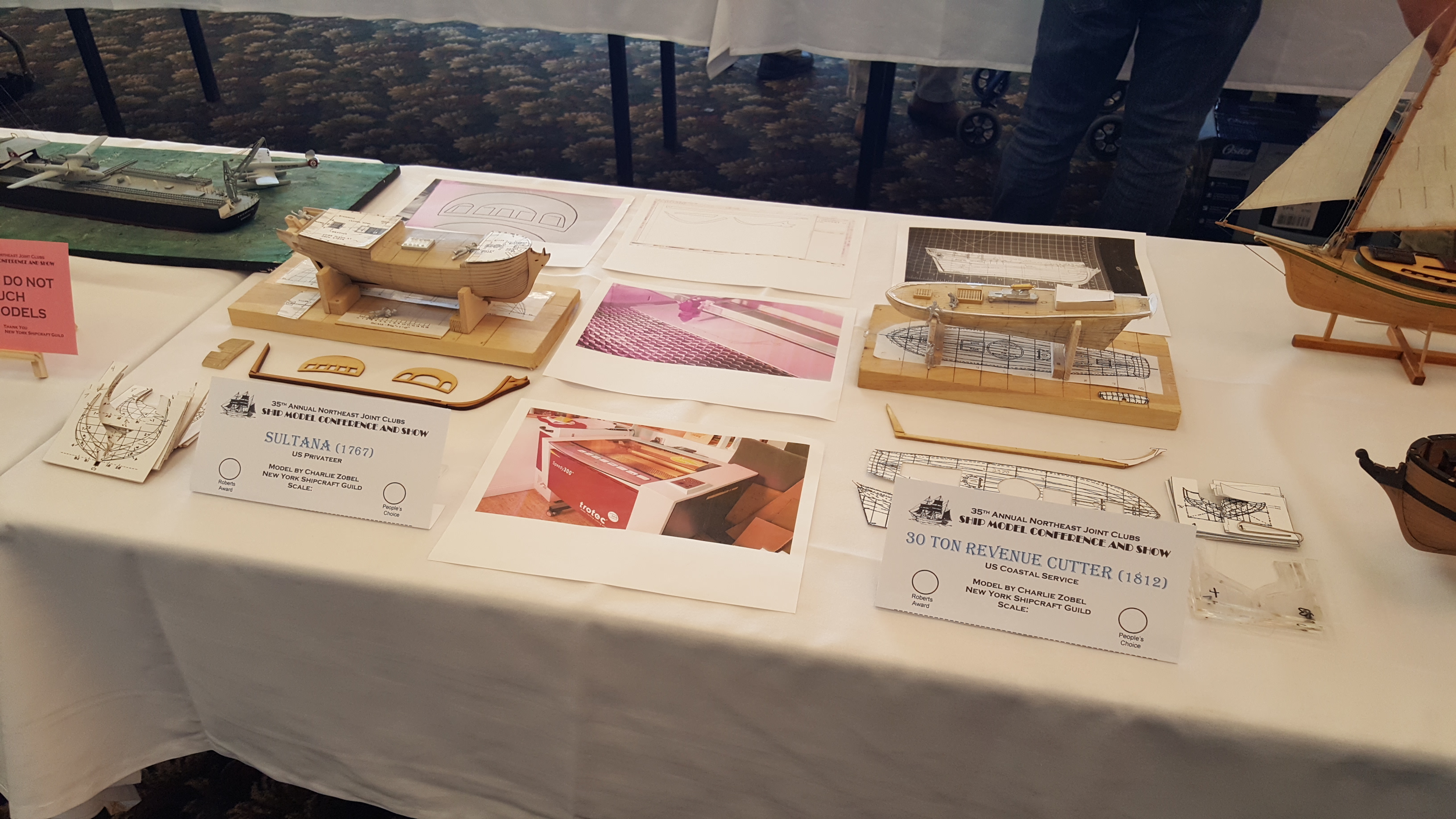
CharlieZardoz got a reaction from avsjerome2003 in Sultana by CharlieZardoz - Model Shipways - 1:64
Below is the carving process to remove the bulwarks. I mainly did this using basic woodcarving tools (though tried the dremel a bit but didn't really need it). The hull still needs a little work by the fore and quarter deck areas. Should I use a small saw to make them even?
-
CharlieZardoz reacted to dgbot in USS Maine by dgbot - HMV - 1/250 - CARD
I am finally back home and in my shipyard. A larger work area along with the rest of my tools. I put my model on my work table and started to look it over to see what damage was done to it.
So far what I found can be redone but will take some time. Here are the major problem areas and the one that gave me the most trouble to begin with.
The area marked is and area that has to be redone do to damage.
I already printed out a new sheet and am cutting out the parts.
David B
-
CharlieZardoz reacted to dgbot in Sultana by CharlieZardoz - Model Shipways - 1:64
You are making headway keep up the good work.
David B
-
 CharlieZardoz got a reaction from Leo-zd in Sultana by CharlieZardoz - Model Shipways - 1:64
Another step was to cut the deck diagram out of the copy of the plans and make templates like so. I used the leftover cardboard from the template sheets and glued them using rubber cement making these deck templates thicker so they wouldn't bend. As you can see lined up on the model itself there is still a lot of wood that needs to be removed from the front stern and sides.
-
 CharlieZardoz got a reaction from dgbot in Sultana by CharlieZardoz - Model Shipways - 1:64
While on vacation I took a trip to The Book Scout in Greenport LI. Any of you who might be familiar this is one of the few places I know that still has ship books and was the place I got my Chapelle books from as a kid. He still had a nice collection and was happy to see the old place was still around. Here's what I picked up
-
CharlieZardoz got a reaction from avsjerome2003 in Sultana by CharlieZardoz - Model Shipways - 1:64
Another step was to cut the deck diagram out of the copy of the plans and make templates like so. I used the leftover cardboard from the template sheets and glued them using rubber cement making these deck templates thicker so they wouldn't bend. As you can see lined up on the model itself there is still a lot of wood that needs to be removed from the front stern and sides.
-
CharlieZardoz reacted to Blue Ensign in Pickle by Blue Ensign - FINISHED - Caldercraft - 1:64 scale
Continuing...
She will now take her place in the Dining Room to compliment the Naval cutter model that I bashed quite some time ago.
They are a good match I think, and more importantly have the full approval of Mrs W
Specific reference works I have used during this build I list here.
The Naval Cutter Alert - Peter Goodwin (Conway AotS series)
The Global schooner - KH Mardquardt
The Colonial Schooner - H. Hahn.
Rigging Fore and Aft Craft - Lennarth Petersson
News of Nelson John Lapenotiere's race from Trafalgar to London - Derek Allen and Peter Hore
My thanks to all who have made such supportive comments on this log which I hope will provide a useful reference to those contemplating the build.
Regards,
B.E.
-
CharlieZardoz reacted to Blue Ensign in Pickle by Blue Ensign - FINISHED - Caldercraft - 1:64 scale
The Ensign Staff and Ensign.
The Ensign was printed on Modelspan tissue.
The advantage of this method is that the exact required size of flag can be obtained with on the model trialling until a size that pleases the eye is found.
A disadvantage of the method more specifically to the White Ensign is that the white background which of course is the basic paper colour does not show to the same advantage as the Red and Blue Ensigns.
To address the problem I coated the modelspan with diluted white water based paint before printing the flag and then painted over the Union colours using again water based paints.
I find that Chisel edged brushes are the best type to use for this action.
The modelspan is only coated on one side prior to printing because I found that coating both sides didn’t allow the printer ink to penetrate sufficiently thro’ to the other side.
Fixed to the flagstaff the ensign was then subjected to a little steam and was teased into shape using rods of differing thicknesses to hold the flag in a drooping attitude.
Matt varnish was then sprayed onto the flag to hold it in position, very light coats are required lest the colours run.
The same method was used for the Union Flag at the Jackstaff; the staff itself was made from micro bore brass tubing with a styrene truck, thro’ which holes were drilled to take the Halyard.
When I set the Union flag on the jackstaff I hadn't noticed that it was upside down, but fortunately my friend Pete Coleman on his forum where this log was originally posted pointed this out and saved me from further embarrassment. Flying the ensign upside down is a distress signal.
The matter was rectified.
A brass fret strip was used to make the tabernacle and the assembly was fixed to the aft face of the bowsprit cap using ca.
B.E
-
CharlieZardoz reacted to Blue Ensign in Pickle by Blue Ensign - FINISHED - Caldercraft - 1:64 scale
A few odds and ends
Rudder coat and pendants.
I usually make rudder coats out of micro-porus tape as it has a sort of canvas finish to it and has the added advantage of a sticky back.
Rudder coats are a sort of bell shape in plan but cutting a pattern for a particular ship is a matter of trial and error.
There should be an element of ‘bag’ in the coat to allow free movement of the rudder
This is difficult to achieve without padding out the interior, I use a little cotton wool off a cotton bud for this purpose.
After this it is just a matter of teasing it into shape around the transom and rudder.
The canvas was tarred to waterproof it as much as possible and I have represented this with a black grey finish.
The Rudder pendants
Evidence is that even smallish vessels like Pickle would have had some system for retaining the rudder after all loss of rudder was no small matter.
I could not find any detailed information exactly how the pendants and chains would have been fitted on Pickle; similar smallish vessels are shown with the pendants taken up over the transom and secured to cleats on the inside. This method would foul the stern gunports in the case of Pickle.
I fitted chains to eyebolts secured in the rudder and to eyebolts in the lower transom, and contented myself with this arrangement for the present.
Anchor buoys
These too are an essential part of a ships equipment, they need to be clearly seen on the water, and the standard size is 54”x 30” with something in excess of 100’ of line.(475mm)
Smaller vessels such as Pickle would have had a smaller version and I scaled mine down to 36” x 20”
I made an egg shaped core from the cone shaped tips of two cheap bic prop pencils and planked these with styrene strip.
With the addition of eyebolts either end and 0.25mm line to form the slings and hoops and the job’s done.
I don’t normally adhere to scale lengths of line but in this case I have measured out 18 fathoms of line (scale of course) to coil on the shrouds.
Nearly there
-
CharlieZardoz reacted to Blue Ensign in Pickle by Blue Ensign - FINISHED - Caldercraft - 1:64 scale
Launch cont'd
Jotika only provide two half chocks to support the boat, the inference being that the boat is supported on the starboard side by the Pickle’s bulwark.
This seemed odd to me so I fashioned a pair of full chocks on which to rest the Launch.
Having spent a fair bit of time making the bally boat, I’m now not sure I like it - hmmn I think I will have to ponder on that.
I certainly think I will only display one boat on the deck even if I decide to go ahead.
The kit arrangement.
How would they manhandle a boat of that size outboard given the rigging incumbrances.
I've a fair idea of how the boats were swung in and out, using a triatic stay slung between the two mast pendants, with tackles attached to ring bolts within the boat to raise it above the bulwarks, further tackles slung from the yardarm, and probably the Fore gaff, to swing it out.
Can you imagine how tricky that could be with an overlarge ships boat, keeping it steady to avoid crashing into the rigging, or worse the masts, she would have to hove to in any case to launch a boat, but in anything other than a millpond sea, she would still be rolling and pitching to varying degrees.
I really wanted to display a boat on the deck, maybe a replacement cutter of slightly less size, and some modifications learned from the building of the Launch.
The 14’ Cutter
This is not a bad shape and at least I know it will fit on the deck without giving the impression of trying to squeeze a quart into a pint pot.
I took a different approach with the Jolly boat.
Exterior planking was done clinker fashion using strips from computer label paper.
I decided that planking the inside of the hull was a waste of time as the planks were hardly visible on the larger boat when finished, and they just add to the thickness of the gunwales.
On this boat I used styrene strip of 0.5 x 1.5mm for the ribs and keelson, 0.5 x 2 mm for the rising plank.
The gunnels I made from 0.75mmx1.5mm styrene strip.
Small boats are tricky to hold whilst working, but a cut out in a block of balsa goes a long way to keep it steady.
To avoid unnecessary thickness I left the ribs long so that they would support the thin gunnels.
Basic internal structure completed, paper patterns for the foredeck and stern sheet gratings
Jotika suggest that there were no bottom boards or knees, but I have modified the interior to reflect the drawings in the McGowan Victory book, and other reference sources.
Bottom boards have been fitted, a grating in the stern sheets, and a small foredeck at the bow. The gratings which are nice features in small boats were left over from the main build but necessitated taking down to a fraction of their original thickness to suit.
Boxwood strip was used for the thwarts and ring bolts fitted at the bow and stern.
Modified chocks.
In keeping with the muted colours of the main model I decided to colour the oars in a natural wood finish, white looked too stark to my eye, and there is no white anywhere else on the vessel.
She certainly looks more in scale to the size of Pickle, so the 19’ launch will not be displayed on the model.
B.E.
-
CharlieZardoz reacted to Devin Poore in Sultana by CharlieZardoz - Model Shipways - 1:64
Off to a great start, Charlie!