


ir3
-
Posts
328 -
Joined
-
Last visited
Content Type
Profiles
Forums
Gallery
Events
Posts posted by ir3
-
-
The TMAX is in the post back to Germany for evaluation/repair. It will probably be around 3 weeks before I get it back sot the sub is on the back burner for a while.
BTW, thanks for the likes. It is very helpful getting me through the trials and tribulations putting the sub together. It is very difficult to get add ons installed with the extremely limited space. The design is excellent for the space and size of the sub and the electronics are probably way beyond what is needed but Engel thought of everything. It will get finished and hopefully no more gotch yas.
-
The problem has been solved concerning the forward ballast tank problem. The spindle screw (attached to the ballast tank piston) extends but does not retract. The problem appears to be in the TMAX. I tried running the forward ballast tank using the connections for the aft tank. It works perfectly both extend and retract. Both of the ballast tanks fail to operate properly when connected to the forward connections. It appears that the TMAX is not reversing the voltage when switching to surface on the forward connections. I have been in constant contact with Engel but just informed them about the problem with the TMAX.
We shall see how this works out.
Until next time,
IR3 -
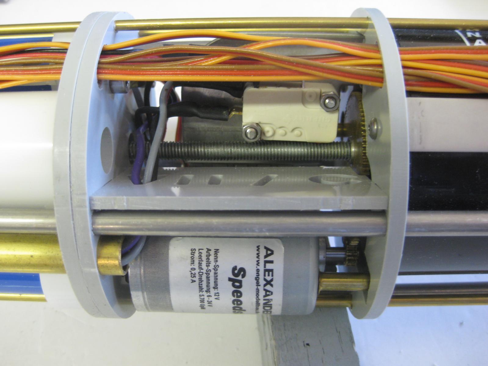
After disassembling most of the Tech Rack the problem was found. The mechanism that operates the linear pot on the ballast tank was colliding with the TAES (static depth sensor that works with the ballast tank controllor) shelf preventing full movement to the limit of the pot.
Problem. The myopic senior did not mount the TAES properly.

The culprit: TAES mounting shelf collided with linear pot mechanism preventing full extension.
The Fix: Notch out the shelf and relocate slightly to accommodate the TAES without interfering with the WTC tube.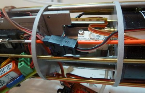
Result: linear pot in fully extended position with no interference.


Now I need to reassemble the Tech Rack.
Until next time,
IR3 -
Well, first the bad news
 , then the good news
  , then the bad news . With everything wired up and ready for testing I forgot to program the RX to the correct channel
  . Also, I wired the RX backwards so Ch-8 was plugged into Ch-1 , etc. By doing this the programming socket for the RX was face down . The good news is that once I programmed it and rewired the servo leads, most of the functions started working correctly .
 For the bad news, the aft ballast tank lead screw is binding either on the aft bulkhead of the battery pack or the forward bulkhead of the servo tray area. It is impossible to see what is happening with the servos in place and the battery pack hardware getting in the way
 . I need to pull the Tech Rack apart to try to find the problem. Of course, now it is greatly simplified since all the wiring now goes aft so it is just a bunch of screws and bolts,
Another problem is that the forward ballast tank lead screw is not moving at all
. Hopefully this is just a bad connection in the servo lead. More on that after the main problem is solved.Until next time,
IR3
-
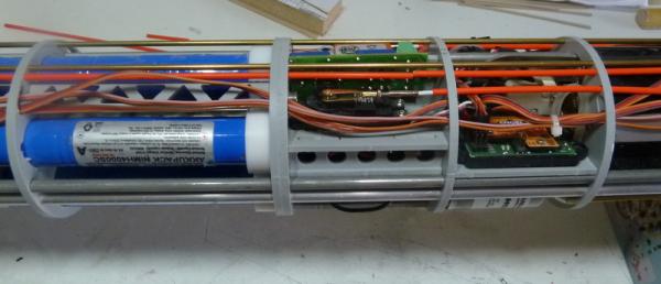
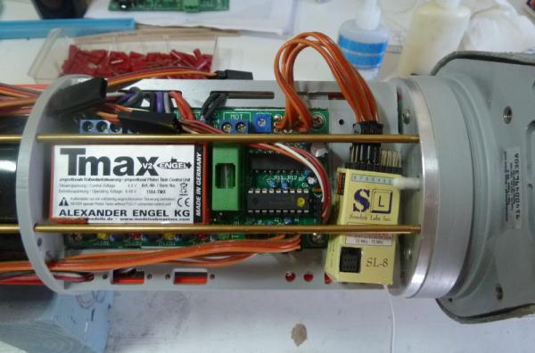
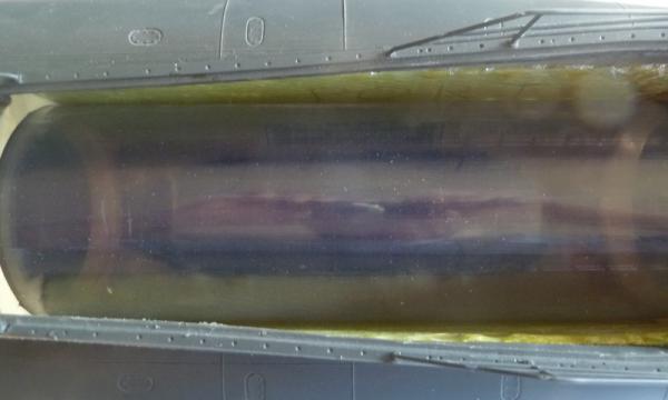
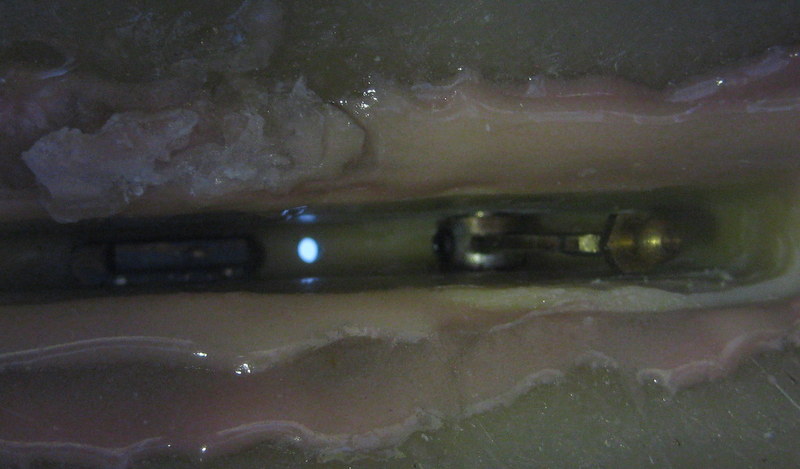
The rewiring is complete. It is extremely tedious since there is no extra room anywhere to tuck leads in that are too long. Each extension had to be cropped to the correct length. There is very little room since the leads have to pass between the WTC tube and the ballast tanks. Preparing the new connectors is no simple task either. Next step is to charge the batteries and start doing all of the static checks.
First Pic shows RX temporarily in place.

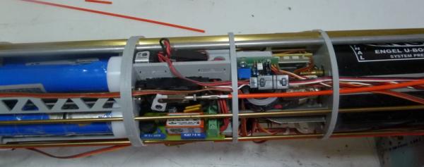
The next three shows how the wiring has been simplified and clutter reduced to a minimum. The antenna lead runs the length of the WTC in a piece of red tubing as seen in 4th picture.
Until next time,
IR3 -
Hi Mark,
Shielding was considered at one time. It was difficult enough to get the wires through all of the slots without the shielding. It was pointed out by several Type VII/C builders that in any case, putting the RX at the fore end of the Tech Rack was absolutely a poor idea. Because of the compactness of the Tech Rack there were very few options as I pointed out. The only reason I am putting the RX next to the rear bulkhead is that the RX sill not suffer any interference from the Brushless motors and the servo leads to the ESC's have noise suppression Ferite cores plus the cable lengths will be extremely short. The best of all worlds. So far I have removed nearly 18 feet of cables. The chances for glitches in the new setup will be quite minimal, I hope.
Iran
-
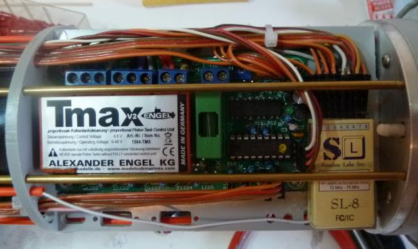
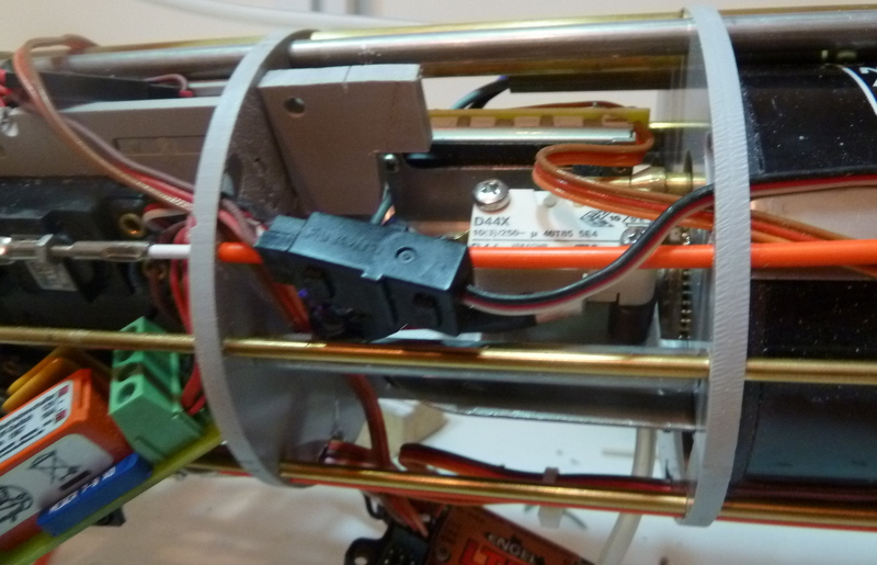
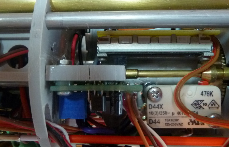
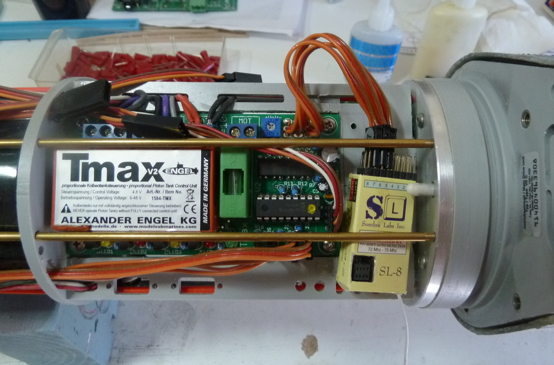
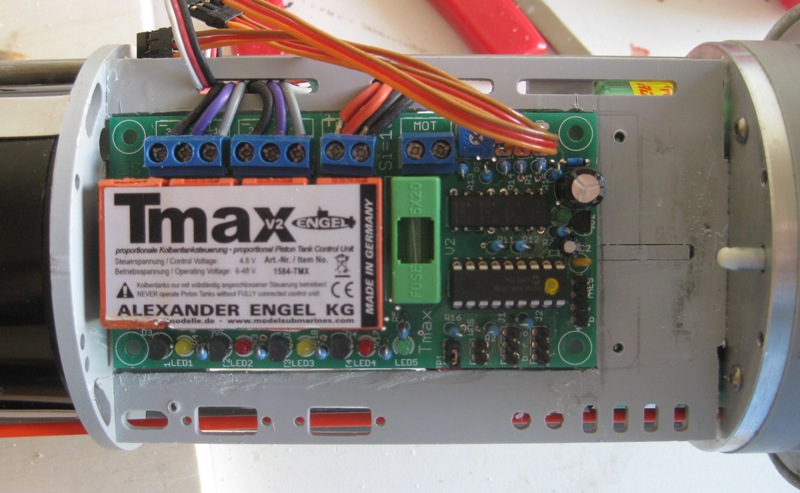
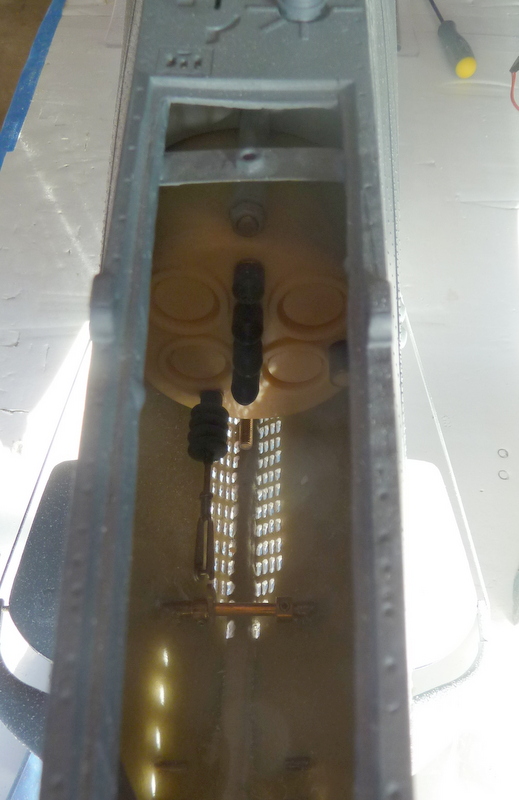
Well after some long thought and research with other Engel Type VII/C builders, the suggested location of the RX is not a good one. It results in very long leads subject to noise and other problems. The question, however, was where to relocat the RX. There were two others but one was very near a brushed motor on one of the ballast tanks and the other was completely aft near the TMAX Ballast Tank controller. This is the spot I chose since the drive motors are Brush Less and will offer no source of interference for the RX. the following pics show the possible locations:
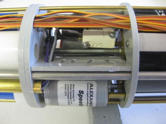
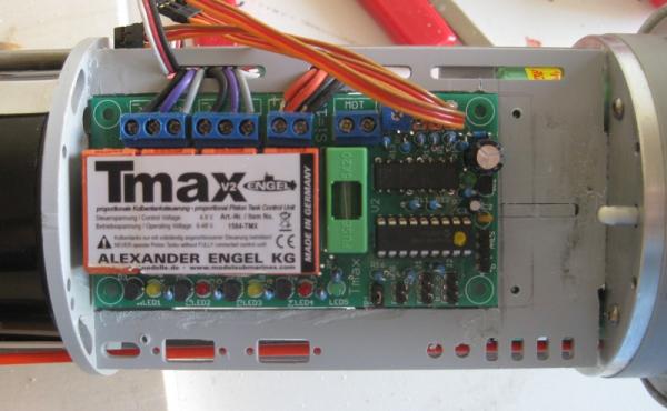
I chose the spot near the TMAX Control Module and it results in:
The RX is loose for the first photo.This reduces the length of the wiring of 3 channels by 1 meter each. The rest of the wiring will be greatly reduced as the leads for the ESC's are in close proximity.
If anyone finds this logic flawed, please let me know ASAP. Making new leads is very tedious.
More to follow.
Iran
-
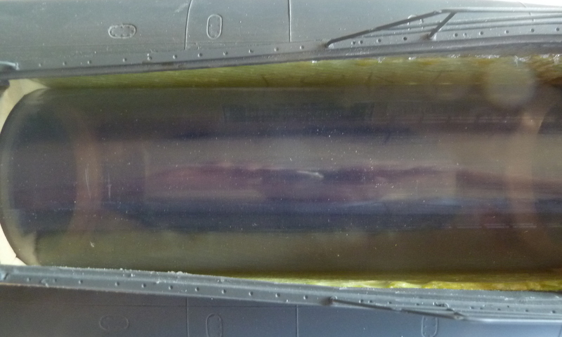
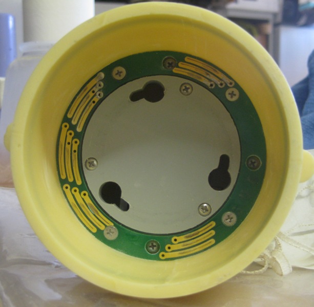
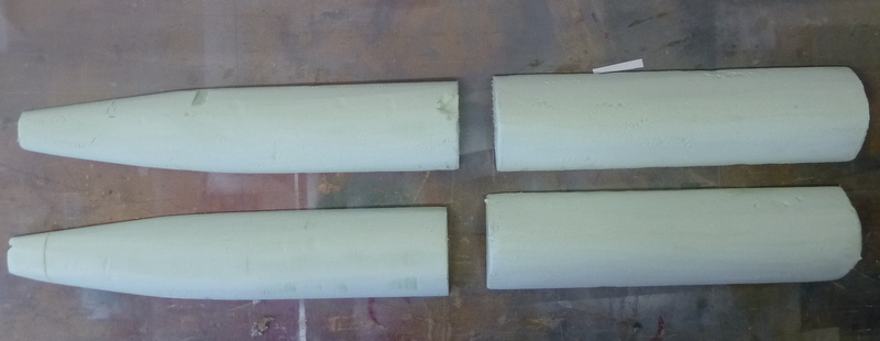
The floats have been sealed and installed. The floats at the aft end of the boat are the same size, just that the angle of the picture distorts the image. The WTC tube is in place but not permanently as of yet. The forward end that goes over the internal nose cone needs to be cleaned and silicon grease applier to help the O-ring seal. The picture with the slip rings does not show the O-ring in a groove around the outside. The WTC Tube slides over this cone and the O-ring supplies the seal. I included a picture of the internal nose cone installation to point out a problem. It will not affect the integrity of the nose cone itself.
The nose cone contains the forward dive plane servo and signals to that are passed by slip ring contactors on the tech rack (I can't seem to find that picture). The bottom bolt is impossible to put on as the end of the screw almost touches the fiberglass hull and I just can't get the nut on. The upper bolt, however, should suffice.
Now it is onto the completion of the Tech Rack wiring and preliminary checkout of all the functions.
Until next time,
IR3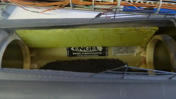


-
The flotation foam has been carved and test fit. The WTC tube does not interfere so I will be filling the pores with resin and install them. The instructions call for installing them with no air pockets or places where water might collect. Good luck.
") There is no way I can check for this. I can't even see the fit for the floats in the aft section of the hull blisters. All I can say is that the WTC tube clears them. The kit manufacturer should have made these pieces. They have the molds that created the hull, thus they have all that is needed to make the floats and have a good fit. Having said that, I will be installing them with Gorilla Glue. Gorilla glue expands while curing and by applying aggressively, most of the space and maybe all will be sealed.
There is no way I can check for this. I can't even see the fit for the floats in the aft section of the hull blisters. All I can say is that the WTC tube clears them. The kit manufacturer should have made these pieces. They have the molds that created the hull, thus they have all that is needed to make the floats and have a good fit. Having said that, I will be installing them with Gorilla Glue. Gorilla glue expands while curing and by applying aggressively, most of the space and maybe all will be sealed.
Next update will be fitting the WTC and putting in the Tech Rack.
IR3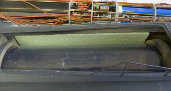

-
The decision to go back to the supplied planking material has been made. On another note, the model has been sitting under the workbench in the garage for over three months and is still perfectly straight. The battle of the twist is over.
The lower counter planking will now be going in.Hats off to the great builders of this model on the MSW forum.
 I studied all of the builds regarding the lower counter and noted Ben's problem that became a major headache. I just checked the shape of the stern area around the lower counter and found that it did not conform close enough to the plans. I will be doing some more sanding and shaping to get this area correct before the planking.
Until next time,
IR3
-
Well, I did try soaking in an 80 - 20 mix of water to ammonia but the results were not much better. Still a lot of spring back and the wood was discolored. I can do the counter in basswood supplied from the kit and this should not be a distraction, especially if I decided to apply a very light finish. What I am warried about is what kind of difficulties I will have when I start the planking. Will I be struggling with some of the compound curves. I know that the boxwood has been used countless numbers of times but I have absolutely no experience in using this material and am wondering if I should just use the kit supplied wood for the entire model.
Any suggestions would be appreciated.
Thanks,
IR3
-
Thanks Augie, that will be my next try.
-
It has been a long while since the last update. Too much in the way but now pretty clear to continue on the Kingfiser. I have all of the boxwood I will need and I must say, not being an expert on woods, it seems quite nice. I am at the point of planking the lower counter. I tried to end bend the boxwood but it looks like it will not happen. I tried two methods to soften the wood, the first being soaking for about an hour. When they came out of the bending jig, the spring back was almost straight, with very little bend. The second method was to soak the planks, wrap them in a wet paper towel and microwave the package to try to get some steam penetration but alas to no avail. It looks like the boxwood does not like to be end bent. This worries me a bit when it comes to planking. Of course the wood will not be end bent for the most part but there are some planks that will have special treatment.
So for the lower counter I am using the 1/8 x 1/16 planking material from the kit. This worked quite well. I am not going to apply it until I get more information on preparing the boxwood as this is the wood I would like to use. Is there some special way the boxwood needs to be treated to get the appropriate bending?
Until next time,
IR3
-
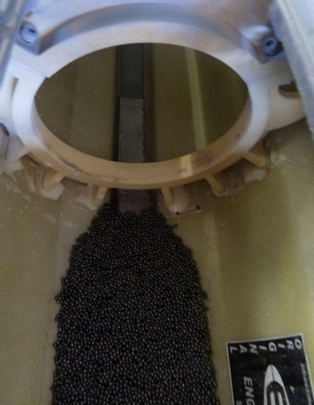
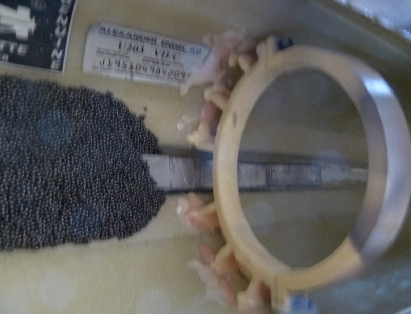
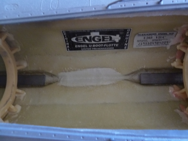
I mixed up some finishing resin and made a soup of 3lbs of shot and resin. It was poured into the center area between the lead strips and smoothed out. A check was made to ensure that there would be no interference with the WTC tube. The pics show the shot in place and the tiered assembly of the lead strips per the plans. One of the pics is slightly out of focus but the idea shows. The rings are the clamps for the WTC tube.
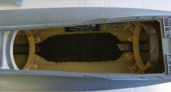

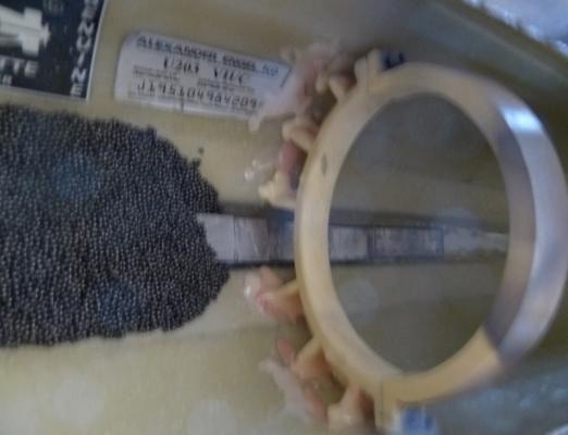
Next step is to get the foam cut and placed into the fuel tank blisters. Apparently there is a balance between the ballast and the foam and I have not found an explanation of this that I fully understand. I just hope that Engel is correct on the amount of foam and ballast.
Next update will be installation of the foam.
Until next time,
IR3 -
The lead ballast showed up today so it's on with getting it into the hull. Unfortunately I did not get feedback on the weights of the battery packs so I had to do a little averaging. The 8000Mah D cells range from 135 to 145 grams. I used the average of 140 grams to get 2800 grams for the old 20 cell pack. The Sub-C cells range from 55 to 65 grams. I used an average of 60 grams to get 1440 grams for the the new 24 cell pack. The difference being 1360 grams or about 48 ounces. The final trimming of the boat, both to the water line and fore/aft will have to take place once the boat is finished and in the water.
The picture shows three bags of lead shot at 1 pound per bag. I need to add the rest of the bar lead per the print and then spread the shot evenly between. An addition of resin to keep the shot in place will probably add and ounce or so, well within the margin of error on the battery weights. Who knows.
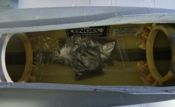
Next update will show all of the ballast in place.
Until next time,
IR3
-
Lovely work Remco. Pebbles is adorable as all kittens are. My cat didn't chase parts all over the workshop but did have one pesky habit. She continuously needed to be the center of attention and would lay down on anything I happened to be working on at the moment, demanding some attention. You've got to love em.
IR3
-
Roger, great work on the R. E. Lee. I built several of these in years past and I see from your build, not much has changed in accuracy. When you first started, was the hull perfectly straight? Thes kits tended to have hulls that had a slight warp in them. Also, I see that you have run into all of the other little 1mm errors here and there but have taken care of them as you go. When they add up, it's a nightmare to get everything to fit properly. This is a great kit but does take a lot of planning and measuring before gluing up the next step. Looking forward to your updates. I am particularly interested in seeing how you handle the railings.
-
The sub has been ignored long enough. I am now working through the next problem to solve. Having switched from the D-Cell battery pack to the Sub-C cell pack, the weight difference is dramatic. I do not have the exact specs of the actual battery weights since they vary based on capacity, a rough approximation makes the difference somewhere between 1200 and 1600 grams (42 - 57 oz).
This represents a lot more lead ballast than was supplied. The plans and lead ballast layout, I am sure, is based on the older D-Cell pack. I have an email to Engel abuout how much extra lead ballast to put in and how to distribute it. He has the exact weights for the battery packs. I would like to avoid experimenting to get the boat to the water line since working within the hull is very cramped.More to follow after I get some specifics.
IR3
OOPS, forgot the picture.

The first layer of lead strips is in but I need more infor before continuing. The space in the center will be used to add the extra ballast as needed.
-
-
-
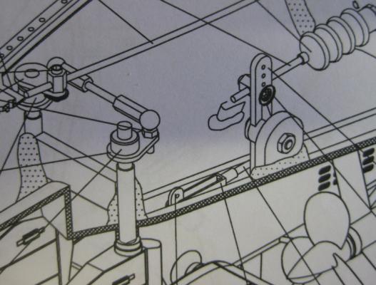
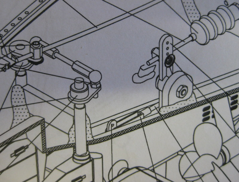
I did a little bit more work on the stern plane geometry and I am now getting about as much stern plane movement that you have achieved. Looking closely at the Engel assembly manual, the linkage is well into the opening in the stern plane support.NOTE THAT THE LINKAGE IS COMPLETELY CHANGED. IT HAS BEEN ADAPTED FROM ANOTHER TYPE VIIC BUILDER, JAN AKA HORSEMAN ON RCG, AND I THANKED HIM FOR AN EXCELLENT IMPLEMENTATION.
I shortened the control arm and placed the ball link in the center. In that way I will not get any interference from the sides of the stern plane support.
I am now getting about +- 18 degrees of deflection. This should be more than enough. I also plan on linking the bow plane into the LTR6 allowing for more help when changing depths.
I have a lot of hours in this and I will do no more on this linkage. As the famous Porky Pig always says "Deb-ebe-de-deb-de that's all folks!"
This has been a lot of work and a good deal of it very frustrating. I am actually sorry I tackled this boat instead of one of the Merriman 1/72 scale boats, which I juts might go back to. His boats operate very nicely in reasonably sized swimming pools. There is actually no clear water pool large enough for this sub in my area. The most I am going to be able to do is use the largest swimming pool that one of our friends has and do a little surface movement, drop to periscope and do a bit of under water movement. The turning radius is so big that I probably will not get a complete turn without backing one of the props. There is no pool in the area large enough to test the full functionality. I will be checking with some of the other U Boat drivers here where they run their boats.
IR3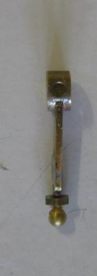

-
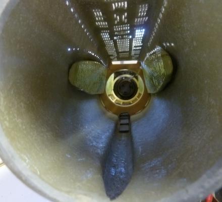
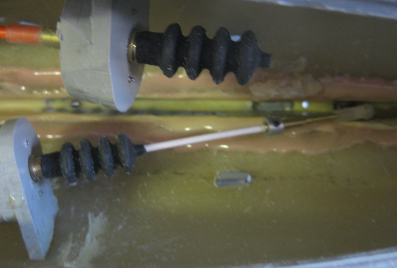
There is not much to report with visual looks but the prop shafts are now aligned and spinning in opposite directions. Now I just have to make sure I have the props on the correct shafts.
 :unsure: Getting the shafts aligned is quit a process. If the stern cone was exact, the strut supporting the dive planes bearing, and the prop hub is accurately brazed then everything might just line up properly with no friction to speak of. Not so fast. It took about 6 hours of fine bending on the prop hub, filing the fairings where the prop shafts exit the hull, and making adjustments to the center strut (I believe it might be called a skeg) and aligning the prop hubs themselver (adjustments in 3 dimensions), makes it quite a task. But the work on the aft section of the sub is complete. Now it is into the WTC and I can set up the forward planes. I have some mechanical advantage issues to work out. I used the notches recommended in the plans for the dive plane bellcrank but I am not getting much deflection with full 90 degree servo motion. Hopefully this will be a simple change of where I connect the dive planes pushrod on the bellcrank. Lots of work!!! I think this is the toughest of the Engel boats to set up. I guess I am just a glutton for punishment.
Until next time,
IR3
-
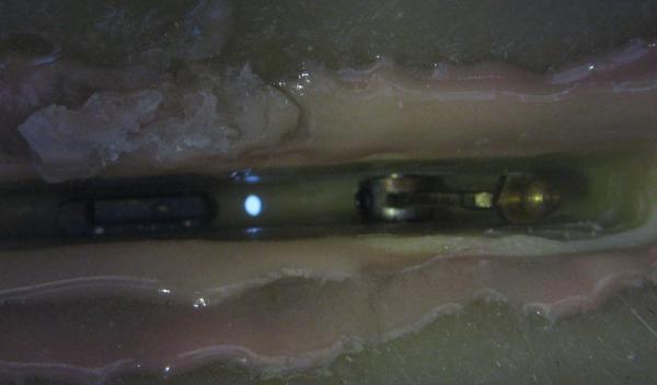
After doing all of the work to create a removable tail cone, at 3AM I awoke with an epiphany. Why not just add a few flood holes in the tail cone to get access to the grub nuts on the prop shaft couplers.
 A little touch up paint and one will never know.
That being done I can now get started on setting up the props and make sure they are turning in the right direction.
Until next time,
IR3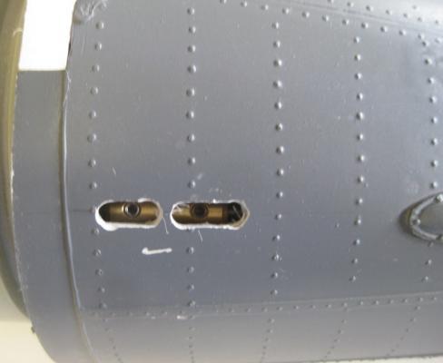
- MarisStella.hr and WackoWolf
-
 2
2
-
The problem with the dive planes servo is solved.
 The LTR6 is a very clever device. It is internally set for a depth of .4 meters or about 1.3 feet. It has a very sensitive pitch sensor and a depth sensor. The pitch sensor, when at periscope depth, helps keep the boat on an even keel. The LTR6 has a connection for a 3 position switch which allows 3 modes, off, relative depth, and absolute depth. With no switch connected, the device is in absolute depth mode. Since the Tech Rack is on the bench it is not at a depth of .4 meters. Therefore the device is commanding the planes to achieve the absolute depth and thus very little control from the TX. With the switch connected and in the off position, complete control of the dive planes comes from the elevator stick of the TX.
These Engel devices are very well thought out and it takes a bit of time to fully understand how they operate.
Until next time,
IR3


Type VII U-Boat by ir3 - Engel - RADIO - model sold
in - Kit build logs for subjects built from 1901 - Present Day
Posted
Hi Ian,
Thanks for the comments on the build. The sub is 78" long and just fits in the SUV with both the passenger front and back seats down. The Tech Rack is quite long at 46 inches and is completely packed. It is a big challenge to get it built and as I have been advised, a bigger challenge to get it trimmed once in the water.
IR3