


ir3
-
Posts
330 -
Joined
-
Last visited
Content Type
Profiles
Forums
Gallery
Events
Posts posted by ir3
-
-
The problem with the dive planes servo is solved.
 The LTR6 is a very clever device. It is internally set for a depth of .4 meters or about 1.3 feet. It has a very sensitive pitch sensor and a depth sensor. The pitch sensor, when at periscope depth, helps keep the boat on an even keel. The LTR6 has a connection for a 3 position switch which allows 3 modes, off, relative depth, and absolute depth. With no switch connected, the device is in absolute depth mode. Since the Tech Rack is on the bench it is not at a depth of .4 meters. Therefore the device is commanding the planes to achieve the absolute depth and thus very little control from the TX. With the switch connected and in the off position, complete control of the dive planes comes from the elevator stick of the TX.
These Engel devices are very well thought out and it takes a bit of time to fully understand how they operate.
Until next time,
IR3 -
Well, after giving the rudder problem a lot of thought the problem has been found. The geometry was wrong on the horn. It should have been on the other rudder post. This not only makes the line of the push rod correct but also has the rudders following rudder stick on the TX. It was quite involved since I needed to redo the cross coupling between the rudders. A very lengthy process.
The problem with controlling the dive planes is that the LTR6 needs to be calibrated. It does not know what level is as of yet so it has no reference to level the dive planes. The servo is just fine, just an LTR6 calibration.
Until next time,
IR3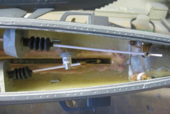
-
With the hull painted it is time to get back on the mechanics. The rudders and dive planes are in as well as the prop shafts and props. Lots to do on the props. There is one right hand and one left hand. I need to determine which side of the boat the props should go and then I will need to reprogram the Brush-less ESC's to get the shafts rotating in the right direction.
With the limited space to work on the rudder and planes installation and my meat hooks for hands it is quite a struggle. After getting everything set up, two problems showed up. For the planes, the servo for the aft planes does not center properly. I swapped the rudder and planes at the RX and the problem persisted with the aft dive plane servo. This will have to be replaced. It is a Robbe 110 BB MG but I think the Futaba S3001 is the correct replacement. I might look for the Robbe locally.
Another issue is a bit of back lash in the rudder system. I do not get a good return to center with the rudders. One of the rudder posts seems to be a slight bit oversize causing the rudder to be a bit on the loose side. I am not too worried about this as I can fiddle with the stick on the TX a bit to get them centered. Replacing the rudder tube is not an option at the moment.
So, the servo will be replaced and then it is off to setting up the props and the dive system.
Until next time,
IR3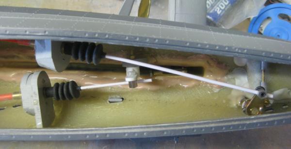
-
Once again incredible work. Late response due to not having a computer for a bit over a week. I can't imagine how the cellphone addicts would get along with out for a week or so. The cold weather is settling in again here in Southern California. Yes, we do get down into the high thirties once in a while.
 I welcome all of the modelers to move out to Southern Cal. As for the cold weather I do have a source of firewood
  :D .
:D .Keep up the great work as usual.
IR3
-
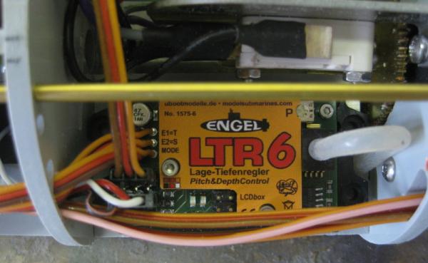
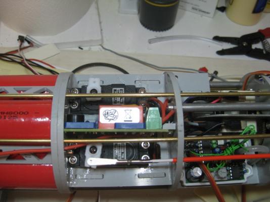
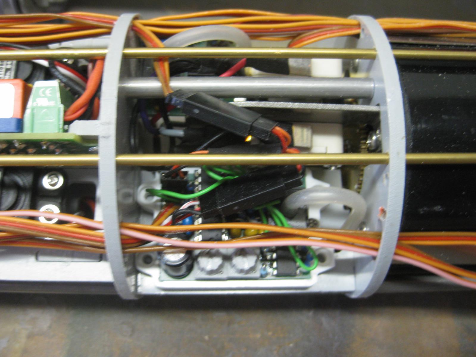
With the computer down for a week and waiting for the delivery of a part from Engel it was slack time for me. The replacement for the Pitch controller LTR5, the LTR6 finally arrived. The installation is very clean and now it is off to recharging the batteries and starting the setup of the electronics package.
The new LTR6 just arrived on Saturday and it is time to install it. It is a very nice design in that it eliminates Y harness to control the aft and forward planes. Not only does it eliminate the Y harness but supplies both +/- servo outputs if the servos are not moving in the right direction relative to the pitch stick on the TX.
The first picture shows the LTR5 clutter and the second shows the clean LTR6 installation.
I will now get started on recalibrating the electronics.
Until next time,
IR3 -
-
It's just about ready for planking with just a bit of fine sanding to get good runs for the planks. A little heavy on the gun port red but thats what planking is for.
I will be using boxwood which I will not have until around the first week in April so this will be set aside and full attention can be made on the Type VIIC.Until next time,
IR3


-
The hull is painted so now I can get back to finalizing the WTC. It is very difficult to get a full view and if I use close ups all of my dismal painting will be exposed.

Still waiting for a new LTR6. It's functionality is improved and includes extra servo plugs. Anything that reduces the wiring clutter is welcomed and it eliminates a Y harness that connects the fore and aft planes. It also has a slightly smaller form factor which is alway welcome in this highly cluttered WTC.
Until next time,
IR3 -
I just completed the quarterdeck gun ports and I am a bit bothered by the process. There are two sets of laser cut parts for the gun ports, some for the quarterdeck and some for the main gun deck. The number of parts for the quarterdeck is over twice the number needed and it appears that the main deck has a significant number too many. Also, each piece for the quarterdeck had to be custom fitted. Am I missing something and using parts that should go somewhere else? This is a bit confusing for me.
Any help?
Thanks,
IR3
-
The lintels and sills are in and faired. I am about to install the gunport framing vertical pieces. There are two basswood sheets with what appears to be the vertical framing pieces. They are not documented on the plans and not referenced in the instructions. I can't find any other references to using these in the instructions so I am assuming that they are the framing pieces. There are a lot more than are actually needed.


Hmm, the camera has distorted the spacing. They are all 3/8".
IR3
Found It!! First sentence in the section for gun port openings.
-
I'm still here. A lot of distractions has kept me out of the shop for a while. Moving along, the Beakhead deck is planked and the beakhead former is also planked. The picture shows the anti twist device, a piece of 1/8 piano wire, in place for the picture. I am keeping it out now since a slight touch of twist in the wrong direction was noticed. With it out, the hull is perfectly straignt. This will go back in as necessary if the hull shows some evidence of the original twist returning.

Now on to the gunport openings.
Until next time,
IR3
-
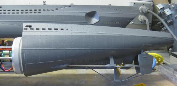
With the mounting tabs in place for the nose cone it was time to get some primer on and after priming, get the rudders and aft planes in place.

It looks a lot better in primer. Next Rudders and Aft Dive Planes in place.
The space to work in on this sub is quite minimal. The Type VII/C's were quite narrow at the stern. Getting to the grub screws with my meat hooks is very difficult. There is still a bit of tweaking to be done to get the rudders and planes zeroed but that will happen when the RX is put back in.

It may look like a lot of space but it is deceiving. The Tech Rack and WTC have been removed for painting otherwise the tail cone would have been mounted with the prop shafts.
It appears that the twist in the hull of the Confederacy might have been fixed. If so, it will be back on that project for a while.
IR3
-
On Jan 9th I reported that I could not get the twist out and started the process of getting the parts to make another hull. In the meantime I left the anti twist device in the hull and left it clamped in the Dremel work bench. Out of curiosoty I removed the anti twist device this afternoon and I believe I am now ready for the home
 . With the anti twist device removed, the hull is perfectly straight. :) This is not to say the it will revert over time but just incase I left the anti twist device in and gave it another spraying of ammonia water. Since I am in the process of painting the hull of the submarine at the moment I will leave the anti twist device in for another 48 hours but checking regularly to make sure I do not introduce a twist in the other direction. With luck I will be back on the build in a day or two.
IR3
-
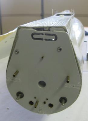
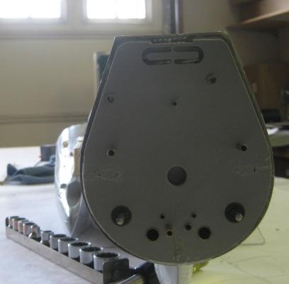
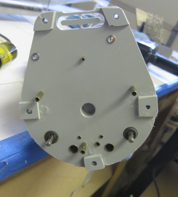
The instructions show the aft section permanently fastened to the rear bulkhead of the Tech Rack. I did not like this since it would make it extremely difficult to do maintenance work on the propeller shafts and the push rods to the aft dive planes and rudder. To solve this problem I decided to bolt the art section to the rear bulkhead using 5 screws.
The first picture shows the blind nuts attached to the rear bulkhead.

The next picture shows the 5 tabs in the aft section. Note also the guides for the rudder and aft planes push rods. Not too elegant but functional.
This basically brings the thread up to date on my progress.
Untill next time,
IR3
-
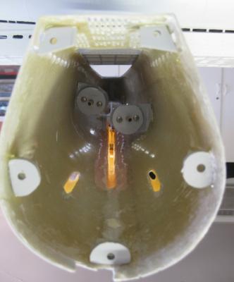
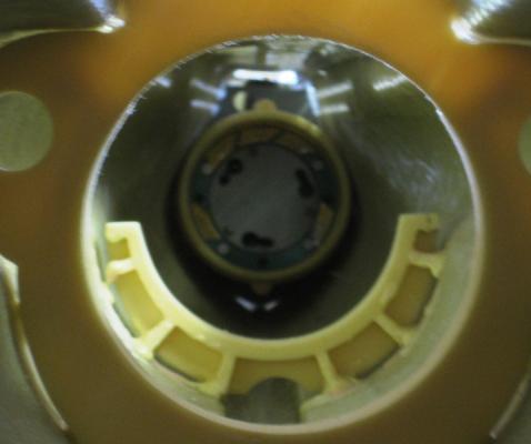
With the mechanical problems in the Tech Rack solved it was time to install the it in the WTC. The next problem and hopefully the last showed up. The bow end of the tech rack has a bulkhead with an O-Ring. This is the forward seal for the WTC. There is a cone in bow that accepts this bulkhead. The bulkhead has 3 adjustable retaining pins and they slide into the cone and with a twist to lock the WTC in place. Well as the first picture shows, there was a bit of a mis-alignment.
With a lengthening of the slots in the cone, a correct alignment was achieved. This was not without great difficulties, however. The nose cone is bolted to a bulkhead which is fitted at a specific spot in bow section of the hull. There are two bolts that hold the cone in place. One bolt is easy to get to but the other is tucked down almost against the hull and is a nightmare to get on and off. I tried flexible extensions, magnetic nut holders, modified sockets but could not get this nut on and get it tightened. After consulting others that have built this sub they agreed that one nut on the top should be OK. The object is to keep the nose cone from twisting when the Tech Rack is twisted in.
After lengthening the slots, difficult to see, the Tech Rack is aligned.
So mechanically speaking, most of the problems have been solved.
Please keep in mind that this kit was not a disaster in the making from Engel. I purchased this sub years ago when we had a very favorable Euro exchange rate. My best guess is that the Tech Rack minus the electronics was a very early design. When the kit was shipped, updated electronics were included. It is most likely that the new electronics were not fitted to the early Tech Rack mounting components but mods were made to later kits to correct the problems. Also, I installed two upgrades and had to make the various changes to accommodate the upgrades.
It was an interesting experience getting the kit to it's current state. From here on, the updates to the thread will be current.
Thanks and until next time,
IR3
-
So now things are really looking up. Most of the electronics have been updated, there is room to make maintainence a bit more easy but yet another problem shows up. The Engel electronics package is very sophisticated. During the initial installation of the components I learned a bit about how they work but since I am still in the construction phase, there is a lot more to learn. Very sensitive pressure sensors are in the electronics package as well as level sensing or inclinometer sensing. You can set the boat to run smoothly at Periscope depth. Once partially or completely submerged it is very difficult to keep the boat level from the operators standpoint. The electronics package is tied into the bow and stern planes to constantly make corrections to keep the boat level. This is over ridden when the operator decided to continue the dive or come back up. It goes on and on. Many fail safes built in. I will elaborate as I go through all of the testing and calibration.
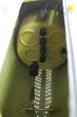
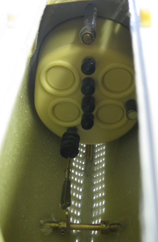
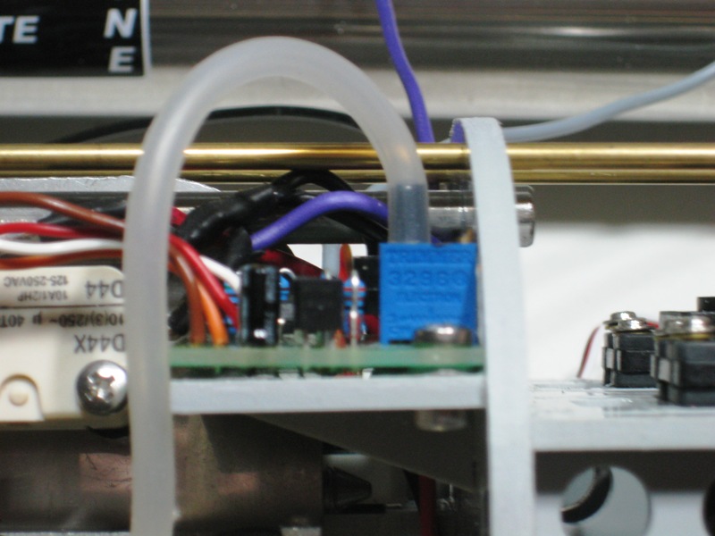
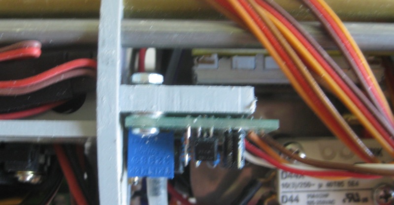
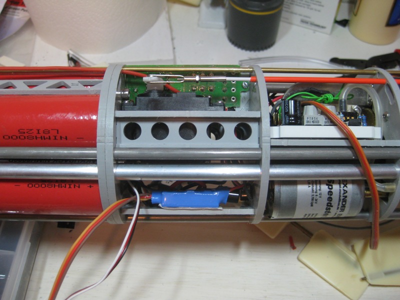
There is a shelf for one of the pressure sensors. The location of this shelf was probably for an earlier version of the sensor. The TAES is programmable from the transmitter and when activated remembers the static pressure at a particular depth. When the sub has no forward motion at depth, this little gadget continuously adjusts the forward and aft ballast tanks to maintain level. The original location for mounting the part did not allow a smooth bend in the tubing coming from the pressure sensing port. This shelf was moved to allow a smoother run of the tubing.
It is a bit difficult to see but the tubing will be kinked when the Tech Rack is slid into the WTC.

This picture, although not very clear shows the TAES remounted with the tubing now inboard and a smooth run to the sensor port..

There is one more problem area that will be covered in the next post.
Until next time,
IR3
-
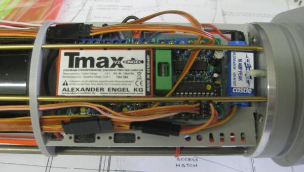
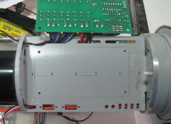
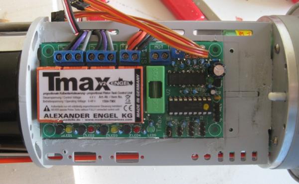
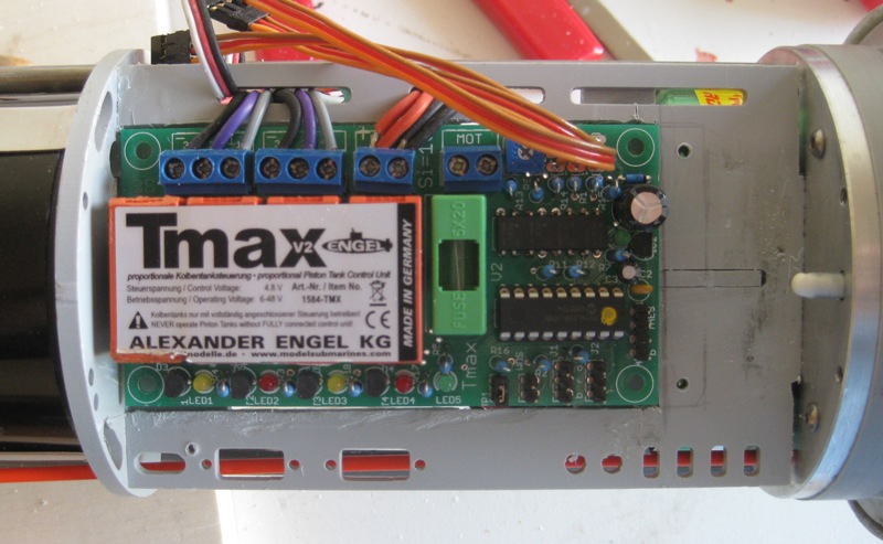
So after getting C cells in, the Brushless Motors and ESC's in and everything starting to look good, uh uh. The brains of the dive system is the TMax VII. This mounts on a platform above the motor/esc compartmant. Well it was a tad too tall and two of the long threaded rods which help keep the long Tech Rack stable interferred with the mounting of this unit. Another modification the the shelf to safely hold the TMax in place needed to be accomplished. This required cutting out an area the size of the TMax and recessing it about 1/4", the thickness of the mounting plate.
This picture shows the interference.
The next few pictures show how the problem was corrected.

And finally the TMax unit comfortably in place. Note that the BEC is no longer mounted.
So now things are looking a lot better for the Tech Rack but there is more to come.
Until next time,
IR3
- MarisStella.hr and WackoWolf
-
 2
2
-
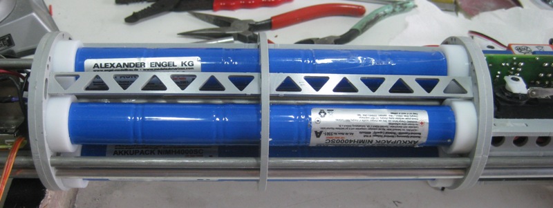
So now everything has been packed into the Tech Rack without a bit of space to spare. Then along comes the Brushless Motors and the Super C battery pack. The nice thing about the new C cell pack is a 4.8V tap is provided. This gets rid of the BEC and a bit more room. Next comes the Brushless Motors and the ESC's. The motors are shorter than the brushed and the ESC's are smaller. All of a sudden space is opening up at the aft bulkhead where the motor shafts exit the WTC. I was now able to move the charge/run sockets to the area near the Brushless Motors and the wiring was greatly simplified.
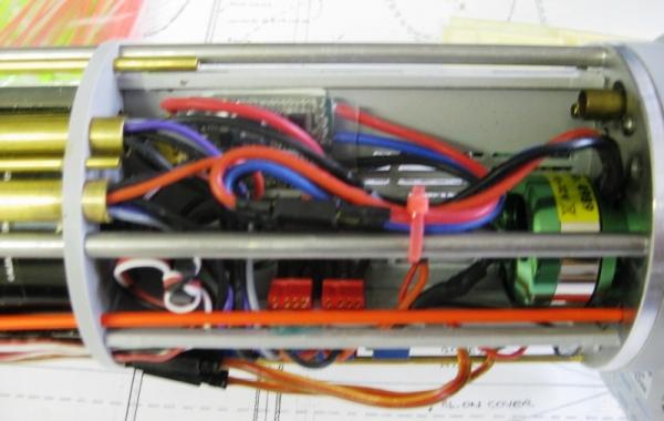
The new battery pack is lighter so some fiddling with the ballast will be necessary.

The magnetic switch was moved to a better spot where it can be sensed through the hull with a fairly strong magnet.
The Tech Rack at this point in time is now looking very functional and not so packed.
Until next time,
IR3
-
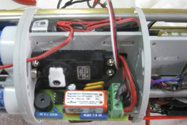
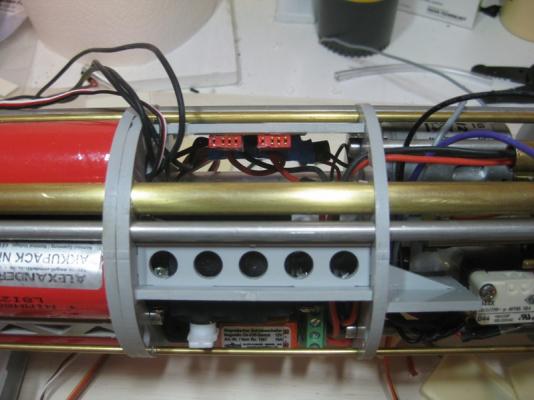
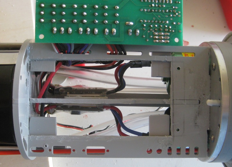
All of the electronics are mounted in what Engel calls the Tech Rack. The Tech Rack slides into a Lexan tube and with O-ring seals on each end of the Tech Rack, the Lexan tube becomes the Water Tight Compartment (WTC). In the original electrical layout, there were no provisions for switching power on/off. This meant removing the Tech Rack from the WTC to disconnect battery connections. The first change that went into the Tech Rack was a magnetic switch that allowed main power to be turned on/off which was great for interday sailing/submarining. The pictures show the installation of the Magnetic Switch and the battery pack with the old D cells. Note that this upgrade was made before changing to the C Cells and Brushless motors.
Until next update,
IR3
AND OH YES, THE ORIGINAL BATTERY PACK CONSISTED OF TWO 5 CELL PACKS CONNECTED IN PARALLEL. A DEFINITE NO-NO. IF THERE IS A SLIGHTLY WEAK CELL IN ONE 5 CELL GROUP IT PULLS DOWN THE OTHER 5 CELL PACK. THE TWO RED CONNECTORS ALLOW ME TO PUT JUMPERS TO PROVIDE POWER TO THE MAGNETIC SWITCH AT THE POND AND ALLOW THE INDIVIDUAL 5 CELL PACKS TO BE CHARGED INDEPENDENTLY. WHAT WERE THEY THINKING AT ENGEL?

- MarisStella.hr, yvesvidal, WackoWolf and 1 other
-
4
-
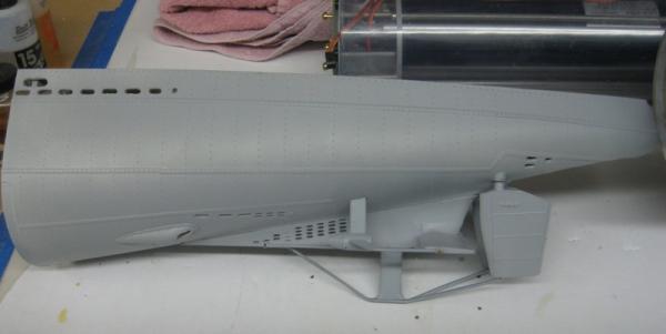
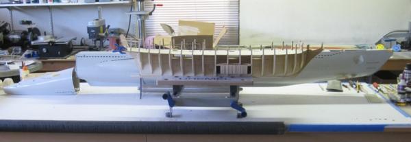
The Engel Type VII build has been going on for some while with the main thread on RCG: www.rcgroups.com/forums/showthread.php?t=1819581. My intent on that thread was to show only the differences in my build compared to most of the existing build threads.
Two upgrades that were not covered in older threads are changes to brushless motors for the twin shaft drive and the battery pack from D Cells to Super C Cells which have twice the power in a package that is about half the size. It took many months to get the upgrades from Engle and the battery pack required another set of upgrades. In time I will summarize what I have done up to now but first a comparison to get an idea of the size. The Tail Cone is off the sub but is shown in the approximate position to get an idea of the total length.
Until next update,
IR3
-
The replacement parts list has been sent to ME and it appears that it might be some time before I receive them so I am back on the submarine project for a while. The build log is on RCG: www.rcgroups.com/forums/showthread.php?t=1819581. I will be starting a thread here which will pick up at the current state of the build.
Thanks for the input up to now and as soon as the parts are in things will again move forward.
IR3
-
Thanks for checking Augie. I believe that everything I will need is covered in my last post and it has been sent to ME Parts.
Iran
-
Need help. I am having a problem determining which laser cut sheets to order from ME. The sheets that came with my kit have no WP numbers on them and no letters A - Z laser printed on any of the sheets. I can only identify the sheets by the thicknesses. I am sure I need A - G but I think on of them is a small sheet with the boat stand parts.
I think the false deck sheets are V and W.
The Shadow Box frame locators were cut on a separate small piece of 3/16 because the originals were not cut properly on the big sheet. These were on sheet B but were not cut properly.
The keel and bulkheads must be A - F. I no longer have the keel and bulkhead scrap.
The keel and stem timbers are on a 1/4 basswood sheet and could be either H or I.
The exposed frames are on a 3/16 sheet and this could be G.
The beakhead frame as well as some of the bow fillers and tramsom pieces are on a 1/8 basswood sheet and could be J or K.
The stern framing pieces are on a 1/8 basswood sheetand could be J or K.
After looking at what I need it appears that there is no ambiguity but if someone could confirm, it would be great. Otherwise it appears that I need the following: A - K and V - W.
Thanks,
Iran
-
Hi Ben,
The twist is quite prominent from the mid frame back. I believe the error started when I attached the keel. The keel pieces were not square. My error. I should have made sure of this when I removed them from laser cut sheet. Once the keel was glued in place clamping the keel to put the formers in probably introduced the slight twist. Of course each frame went in dead center and square to the bulkhead former but the twist was surely still there. Then came the filler blocks which also went in just fine. I did mount the beakhead former a bit out of line but corrected that assuming it was an optical illusion when I sighted down the hull at that point. It was after I assembled the transom that the glaring twist showed up. At that point I guess it was too late. Lesson learned. I am sure I can get the pieces I need from ME and start over again.
Thanks for your input,
Iran


Type VII U-Boat by ir3 - Engel - RADIO - model sold
in - Kit build logs for subjects built from 1901 - Present Day
Posted
After doing all of the work to create a removable tail cone, at 3AM I awoke with an epiphany. Why not just add a few flood holes in the tail cone to get access to the grub nuts on the prop shaft couplers.
 A little touch up paint and one will never know.
That being done I can now get started on setting up the props and make sure they are turning in the right direction.
Until next time,
IR3