


ir3
-
Posts
326 -
Joined
-
Last visited
Content Type
Profiles
Forums
Gallery
Events
Posts posted by ir3
-
-
I have had so many problems getting the prop shafts to line up and getting the Lurssen effect working that I decided to just do a static build. I can see now what the kit manufacturers go through to engineer running gear in the models. It is above my pay grade. If anyone wants to try a motorized version of this, please let me know. I have all the components removed and may offer them. Thanks for the followers. When I get back to working on this, I will do more posting.
- mtaylor, lmagna and Old Collingwood
-
 3
3
-
Yes, I do believe it will be quit fast.
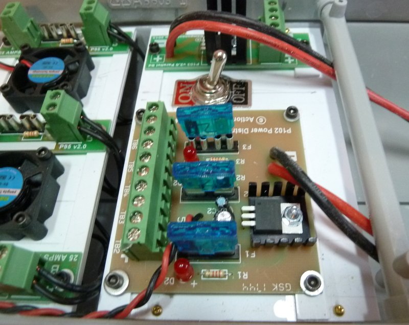
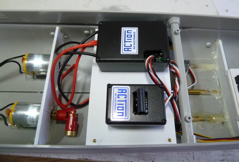
Electrics installation is just about done. The Power Distribution board, the Battery Combiner board and ON/OFF are installed. The switch is a Double Pole ON/OFF so instead of disconnecting batteries when done for the day, the switch will connect the positives of the batteries to the Battery Combiner. The Battery Combiner will run with just one Battery connected so depending on weight distribution I can run 1 or 2 batteries. When wiring the batteries, I might use a Deans 2 to 1 connecter so I can hook up the charger without taking out the batteries, TBD. The last of the installation will be a suitable location for the RX. I am still using my F-14 Marine radio running on 75MHZ. The RX position should not be a problem if kept away from the ESC's.
Until next time,
IR3
-
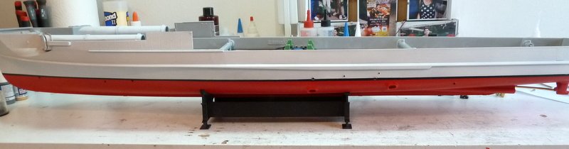
Once again, thanks for the likes and the comments. The hull has been painted and final installation of electronics and running gear has started. I absolutely hate painting so no micro close ups of this paint job. When I paint the model it comes from the shipyard with battle damage. If it came to a choice of painting or going to the dentist for a root canal, in the words of a famous old comedian, "I'm thinking about it". But, oh well, my goal is to have a reasonably acceptable model but testing of the Lurssen effect it on the top of the list. We will not be getting any closer to the model to check out the paint job.😀
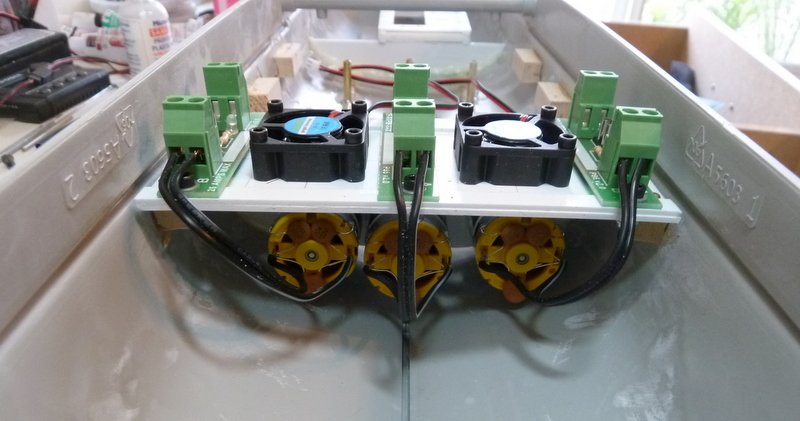
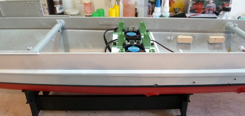
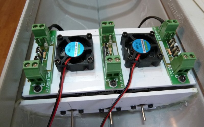
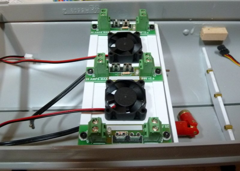
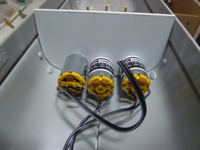
The motors are in as well as the fuse boards and fans. The motors are wired to the fuse boards. Nice to have all screw connections. The fuse/fan board fits nicely and has ample clearance to the deck. I think with the deck house on there will be enough openings to get some cooling air in. Also, some hatches will be open so hopefully some air will exhaust through them. I am not too worried.
Until next time,
IR3

- lmagna, GrandpaPhil, BenF89 and 4 others
-
7
-
Hi Mark,
There will be a few open hatches. Hopefully it will be enough. About the torpedoes, Merriman sold a torpedo kit for the 1/72 Revel Gato running on compressed CO2. I suppose that one could use the same system here but probably not. But, a very interesting question.
Thanks,
Iran
- Old Collingwood, lmagna and mtaylor
-
3
-
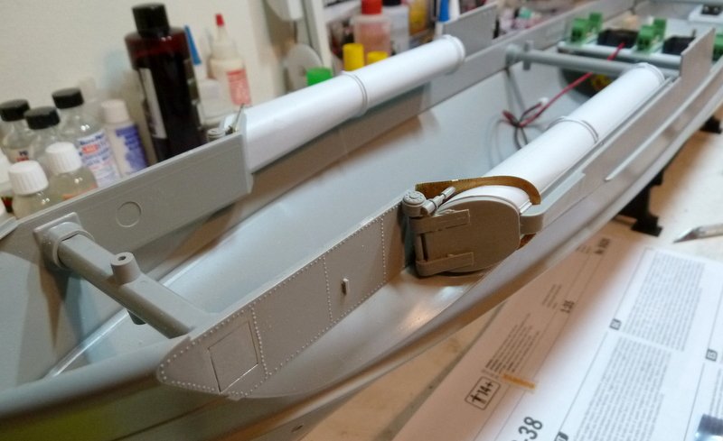
The fans just arrived and will be installed tomorrow. The fans should keep a reasonable amount of air moving across the motors. While waiting the torpedo tubes were installed. Before going too much further the hull needs painting. I will be doing flat white above the water line first and then follow up with the rest at a later date. It'll be easier to do the painting above the water line before any decks and deck detail is added. Also waiting for the rest of the electronics.
Until next time,
IR3
-
Thanks Lou,
The Hansen Dam boat pond is quite large. The Irregulars used to meet regularly but that has dropped off quite a bit. The Violators group is on the pond on Saturdays and they are running the fastest boats around so there is plenty of room. I do not have a programmable radio so it is great that the P94 has a lot of options and several mixing modes. As soon as I have all the electrics I will do a water line test. I purchased the Dual Battery adapter from Action and so to make up the weight I can experiment with one or two battery packs at different weights or simply use some shot ballast.
I have the fuse blocks in place above the motors and room for two very light 30mm square fans. If the motors to not get too hot they can be removed.
Until next time,
IR3
-
I do appreciate all of the input you are providing. The power source will be 7.2V but probably closer to 6.5V due to losses. I never did a 3 prop boat and from your input and the P94 setup instructions, it is not quite as simple as one would expect. The prop diameters are 1.25" so that will affect the analysis or the current flow somewhat. The P94 has 4 modes of operation. Mode 4 is what they suggest for MTB's such as this one. In Mode 4, the center prop is slowed down in turns by a proportionate amount TBD by rudder movement, In another mode, the center motor speed does not change with rudder movement. The mix is adjustable from 50% to 100% so this will be set in trial runs. It's quite complex as to how the transmitter sticks control various outer prop configurations depending on movement of left and right sticks. I have a lot of studying to do on this. But I think that with the larger props the loads will be a lot greater so perhaps putting a fan above the motors can't hurt.
I read some other experiences about the Lurssen effect on the S100. Some reported no effect until near top speed. Others used only the center motor in which case the Lurssen effect would not work at all. I think this is correct as the effect depends on the outer props which have a big influence on the stern wave. There is no definitive discussion of this effect as applied to the S-38 or the S-100. It will be interesting once the pond runs are made to see what actually happens. It could end up with a lot of effort and get very little result. But it is fun doing the implementation. I did find a picture of an implementation that has the outer rudder servo offset from the center line to keep the geometry correct. In the design that I first followed, the geometry was all wrong and it probably didn't work at all. The build thread never made it to boat on water.
A bit winded but in the meantime, more parts were ordered from Action so the complete installation of electronics will be set back a few weeks. I will continue installing the parts that I have.
Until next time,
IR3
- mtaylor and Old Collingwood
-
2
-
The spec on these motors is 5.9A at 22000 rpm. I'm not so sure I will run the motors at top speed so the current draw will be somewhat less.
- Old Collingwood and mtaylor
-
2
-
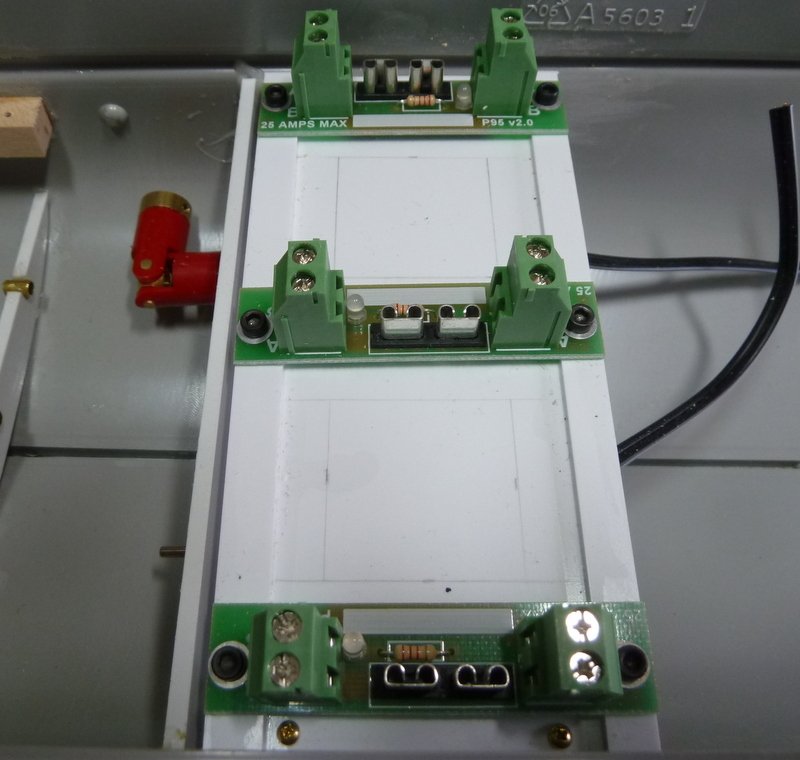
Started on the electronics installation. All the electronics will be on boards that can be removed in case repairs are needed. The first items to install were the ESC's for the motors. I used the action P94 "Lite" for the outer motors and the Action P79 for the central motor. The fuse blocks will go on a panel just above the motors. There is a problem with cooling the motors. I purchased the Traxxas Heat Sinks for 380 motors but unfortunately they just don't quite fit the RE380 motors. They are supposed to snap on but this will take considerable effort. So, when I install the fuse blocks above the motors I will include a small fan to keep air moving around the motors. I forgot two items from Action (a senior moment) and I have to order them. That should delay the final installation of electronics for a few weeks. There is a lot to do, however. Here's the pic of the ESC's mounted in their respective boxes.
Until next time,
IR3
- mtaylor, lmagna and Old Collingwood
-
3
-
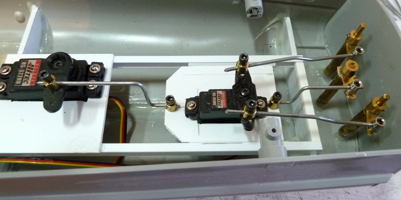
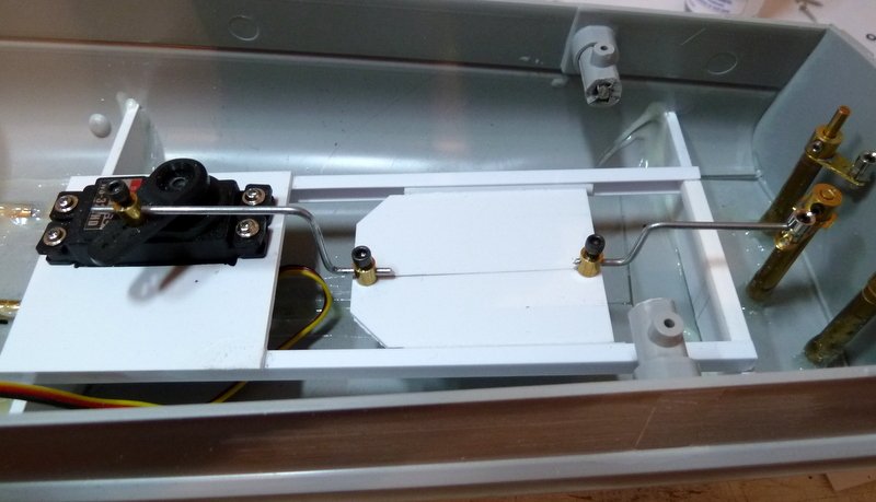
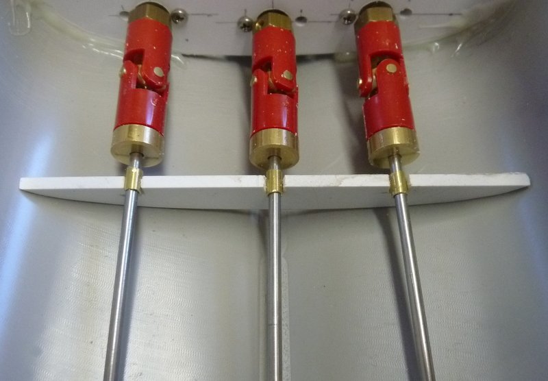
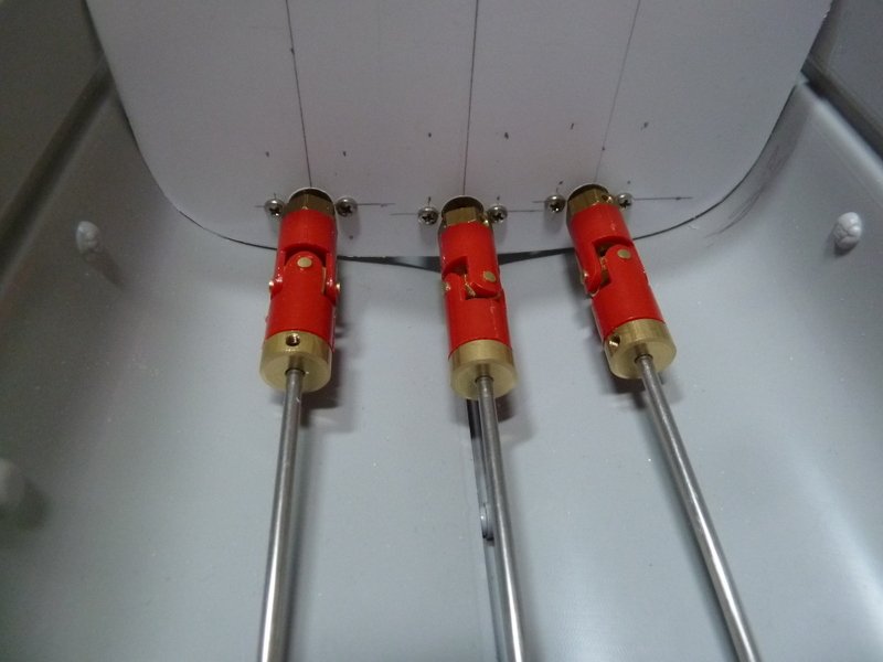
Nearly there. All of the geometry is now correct. All the rudders are moving at the same rate and I am just about finished with this setup. I do notice a bit of flex in the rudder tubes so these will be reinforced. There is a little bit of skewing of the sled so I moved it as far back towards the stern as I could. The skewing seems to be a bit less. The only test to see if this works will be on the water. Next will be the installation of the Action electronics.
Until next time,
IR3
-
Thanks for the input, Lou. I will have to go through your explanation a few times to fully understand it. I have a Vario CH53 that I will be finishing in the late spring and the comments will be very useful.
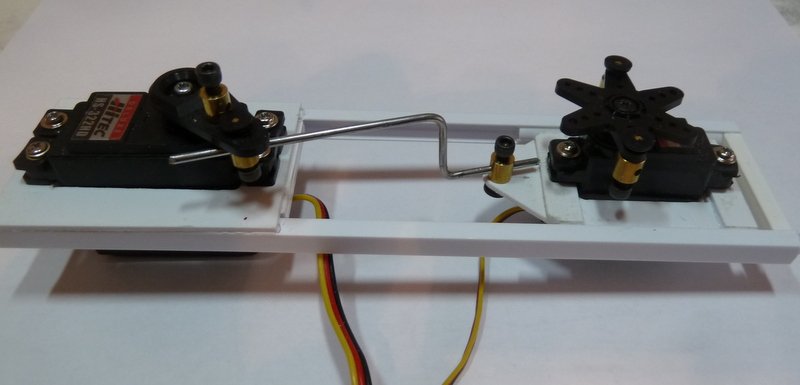
After giving it a great deal of thought, the first implementation was too complex. Geometries were all off. I didn't like having two different connectors on the large servo arm which caused the sled to move differently than the main rudder. The solution is to have the servo push/pull the sled and have the sled push/pull the rudder. In this way all the linkage is kept in a straight line. The position of the connector on the servo horn is exactly the same distance of the connector on the main rudder horn. Geometry is perfect!
Now it's off to putting the Lurssen servo on the new sled. This will be positioned so that the angles to the small rudder connectors will be exactly the same. The result is that when the large servo moves the sled the main and outboard rudders will track exactly the same.
Here is the new main rudder implementation. Now its back in the shop to install the small servo and put this part of the project to bed.
Until next time,
IR3
-
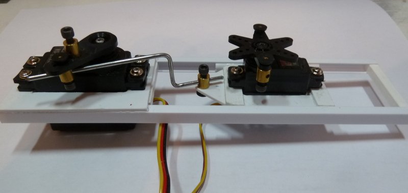
Well, after banging my head against the wall trying to get the outer rudders aligned, it became perfectly clear that the small servo must be centered between tiller arms. The geometry is all wrong with the current implementation and the rudders do not sync. I will be widening the sled to accomplish this. Now that I know how to build the sled, it should go quite quickly.
I should have it all posted by tomorrow afternoon.
The discussion is great. Lurssen was quite an innovator.
Till next time,
IR3
- lmagna, Old Collingwood, Canute and 1 other
-
4
-
Thanks for all the likes and the input on the Lurssen Effect. It is quite intriguing as Ben pointed out. The reason I chose this model is because of this implementation. Seeing this working on the water will be quite amazing.
As far as the work goes, getting the geometry of the 3 rudders correct is getting to be a bit difficult. Unfortunately the two outboard rudders are quite close to the back of the hull so getting the tiller arms at the correct angles requires a bit more work. Moving the outer rudders with the small servo can be limited to about 30 degrees. The problem is with the center rudder movement. I may not be able to get a full 45 degrees on the main rudder but this would be quite drastic anyway. The small servo definitely needs to moved off center to get the angles to the outer rudders as close to equal as possible. This is a bit more trickier than I expected.
Until next time,
IR3
- BenF89, lmagna, Old Collingwood and 2 others
-
5
-
nThanks for the question, hope this helps. My total knowledge about this effect is well below the marine engineers level of expertise but the concept makes a lot of sense.
The larger servo, the one on the left moves the center rudder and pulls/pushes the sled simultaneously so that all 3 rudders track together. This is the normal, no effect configuration. Note that all the tiller arms are pointing in the same direction so the sled just acts as an extension of the larger servo arm. The smaller servo does not turn (until the Lurssen effect is desired) thus the outer rudder arms pull/push as if they are being controlled by the larger serve. So they track in a straight line AND while turning. Normal operation for 3 rudders.
Now the Lurssen effect. The faster the boat goes the deeper into the water the stern sinks. Note the parallel with hulls that are designed for racing. At low speeds the hull is deep in the water but at speed they are almost riding on the prop only. The S-Boat hull is optimized for up to 20 knots for a long cruising range so the smaller servo is not turned as the outer rudders would drop the efficiency of the boat. Now at higher speeds the stern lowers in the water and the nose comes up dropping the efficiency so the smaller servo is activated to move the outer rudders away from the center line. This changes the way the water moves under the stern and lifts the stern up and the nose back down for a more efficient configuration.
When the boat turns at speed steering by the large servo still keeps the movement of the outer rudders in sync with the main rudder. So if it is a turn to starboard at speed, as an example, the starboard outer rudder increases its angle from the center line and the port outer rudder lessens its angle from the center line thus maintaining the effect through the turn. The starboard side of the boat wants to sink into the water further, in this example, as the boat turns. So the starboard outer rudder deflect s the water more than the port outer rudder does thus lifting the starboard side of the hull out of the water more than the port side making the turn more efficient.
Very difficult to explain in words as I am not 100% fluent in the dynamics but the principle makes a lot of sense. It allowed a hull which was optimized for around 20kts (normal cruise speed) to be very efficient at attack speed of around 40kts. A lot easier to alter the shape of the water going under the stern than change the shape of the stern. 😊
-
-- THIS ITEM HAS BEEN SOLD OFFSITE --
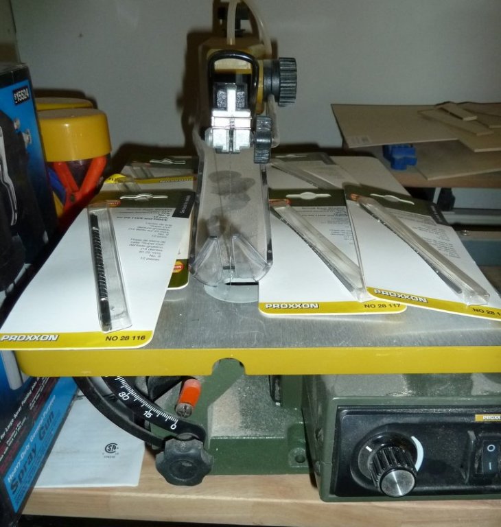
If anyone is interested in a Proxxon DSH/E variable speed scroll saw I am parting with mine. When I thought about scratch building this was probably a good scroll saw to have. As it turns out it is much too big for me. I am doing small wood and plastic boat kits and my Micromark scroll saw is perfectly adequate for my needs. I have 6 packs of extra blades to go with it. It has been used sparingly and so it is pretty close to new. It is 120V version. It's a bit dusty but will be perfectly clean when shipped.
Asking $300 and will split shipping. I am not sure of the actual box size or weight but will be very happy to work out the numbers if anyone is interested.
Thanks for looking.
-
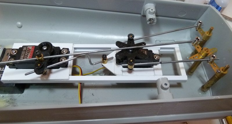
The mounts for the servo tray are tacked in will be finished by next update. The clearance between the main rudder pushrod and the small servo is a bit tight. A washer or two under the main rudder tiller arm should take care of that. Tomorrow the servo testers will be put to use to fine tune the linkages and get the rudders aligned.
Until next time,
IR3
- Old Collingwood, lmagna, mtaylor and 3 others
-
6
-
I now have the basic setup for the rudder controls. There are a few minor problems to work out but the principle is there. Unfortunately one of the deck mount hull spacers had to be cut away to make room for the pushrods but this should not be a problem. The original designer had the same problem. The only item I would like to find a solution for is the main rudder push rod and the sled push/pull rod attachment to the servo arm. Notice how they are spaced in order to fit on the servo arm. If anyone knows of a way that I can install them the same distance from the center of the servo please let me know. The way the setup is, the outer rudders/deflectors will not track the main rudder exactly. Perhaps it is not a problem???
Until next time,
IR3
-
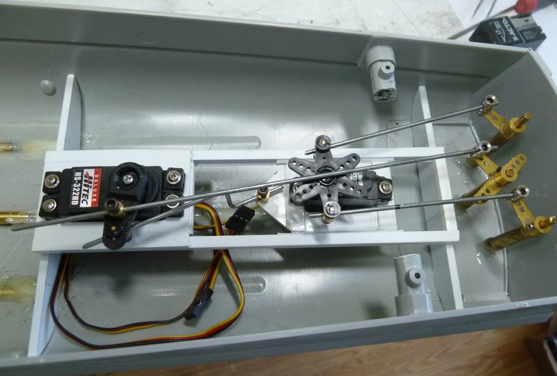
Started on the RC components. The first part is the rudder/deflector mechanism. This is not my idea but just adapted from another build. It is very clever and above my creative abilities at this time.
There are two servos, the large one that controls the central rudder and the smaller servo which controls the outer rudders/deflectors. The small servo is on what I will call a sled. With rudder amidships the linkage from the small serve to the output is adjusted to keep the rudders parallel. There is a link between the large servo and the sled. When the main rudder servo turns to deflect the main rudder the sled is push/pulled to keep the outer rudders in alignment with the main rudder. The small servo remains centered thus allowing the rudders to track. At speed, the smaller servo is turned to move the outer rudders away from the center line thus adding the Lurssen effect. This is manual but I suppose with a computer radio this servo could be controlled by the throttle?????.
The two pictures show the sled in the fully extended and fully retracted positions.
Next, this servo tray needs to be installed in the hull.
Until next time,
IR3
-
Thanks Lou for the suggestion. Never passing up a good idea, the pieces for the shaft support behind the U-Joints is fabricated and test fit. The shafts turn smoothly so the next step is to tack it all in and finalize the installation. Getting the center prop shaft in position is a problem since it can not be installed from the stern like the outer props. The center motor needs to be removed and I need to make sure I can do just that when the boat is completed.
In order to install the RC Gear and make it removable, I need to get the main deck fitted and make sure that it can be removed for making repairs. This will probably keep me busy for a day or two.
Until next time,
IR3
-
Hi Lou,
Thanks for the heads up on possible vibrations at high speed. I will be installing the electronics in the next few days and will test the props at speed to see if vibrations occur. Putting in bearings sounds like a good idea anyway. I just need to find a way to that it doesn't block the ability to get at the screws that hold the motors on the bulkhead in case of failure.
Until next time,
IR3
- mtaylor, Old Collingwood, lmagna and 2 others
-
5
-
-
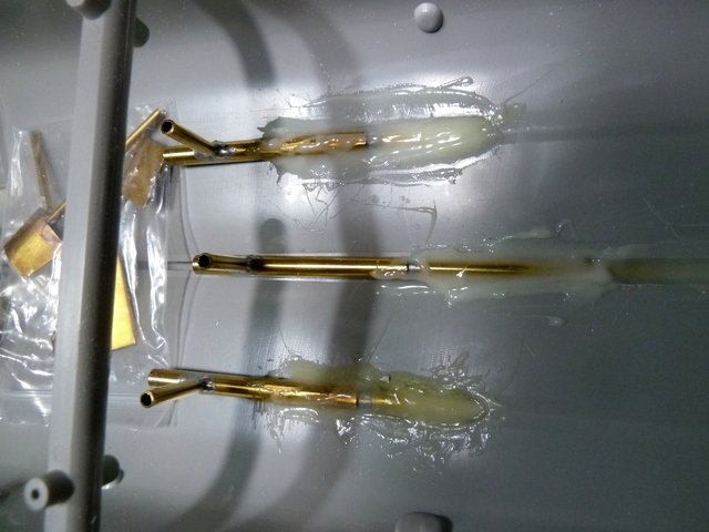
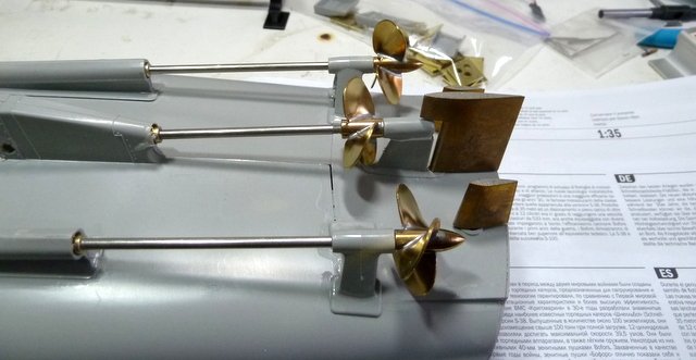
The couplings have arrived. The motor bulkhead was cut from 1/8" styrene. To get the shape I used a piece of soft brass strip and formed it to the inside of the hull where the bulkhead will go. Then transferring to the styrene and cutting and drilling. Temporary installation with the bulkhead slightly tilted. The shafts do turn smoothly. A slight misalignment in the starboard prop shaft. Very difficult hollowing out the stuffing box covers and getting perfect alignment. The slight difference should not be a problem. Now for a permanent installation.
Until next time,
IR3

- LEGION 12, yvesvidal, GrandpaPhil and 6 others
-
9
-
After posting a question on removing large amounts of plastic from parts of the model I was encouraged to start a build thread. This will be an RC Conversion inspired by ojays on RC Universe. One of the main reasons for building this model is to implement the Lurssen effect as was done on ojays thread. I am not so sure the effect scales down to a model of this size but implementing will be an interesting experience. The Lurssen effect is to adjust the angle of the outer rudders/deflectors to reduce the effects of the stern wave at speed. By changing the angle to proper value the stern wave produces minimum drag. The angle is optimized for a particular hull.
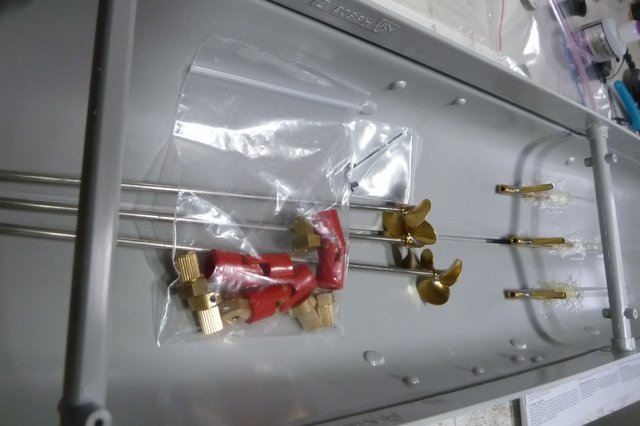
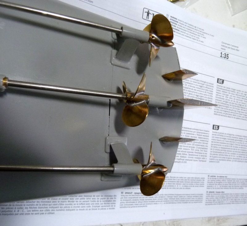
The hull halves were fastened together and installation of running gear was started. The running gear was purchased on eBay as a package including the rudders, prop shafts, stuffing boxes, and props. It also included the center strut and outboard struts but for some reason they did not fit this hull so were excluded. It will use 380 motors and electronics from Action. The pictures show the startup. There is a bit of filling and cleanup still to be performed.
Since I am waiting for some items from overseas I decided to scatter the work using what I have available at the moment. PE will be Eduard 53212 and Eduard 53214. The kit comes with some PE and I will be using pieces from each. I dread using PE as it is nothing but a struggle for me but I decided to take my time and be patient. We shall see what results follow.
Until next time,
IR3
-
Thanks for the inputs. Drilling out the center with the largest drill possible helped a great deal. Most of the other work was done with a Dremel drum sander except near the hinges. These needed a fine file and very sharp Xacto blade. There were no narrow chisel tips in the LHS which would have helped a great deal. Thanks for the suggestion on the build thread. I wasn't planning on one but there are not very many on the net so I think I will. I thought they may be skylights for the crew but being the engine room skylights makes a lot of sense.
I'll continue in a build thread.
IR3
- Canute and thibaultron
-
2

S-38 Schnellboot by ir3 - Italeri - PLASTIC - RADIO
in - Kit build logs for subjects built from 1901 - Present Day
Posted
Mark, thanks for the reply. My biggest problem is running across something interesting and different and I just have to do it. Like implementing the Lurssen effect on the Schnellboot. I am too quick to gobble up an old kit only to realize that getting the running gear and fitting kits will be almost impossible and so more improvising. The Schnellboot was an interesting adventure but started taking up too much precious time. I do have some very nice Steam projects that I have collected over the years and will concentrate on them. For sure, there will be no improvising on them, just straight forward builds with excellent instructions and steam plants designed directly for them. Time is moving on too quickly.