


ir3
-
Posts
336 -
Joined
-
Last visited
Content Type
Profiles
Forums
Gallery
Events
Posts posted by ir3
-
-
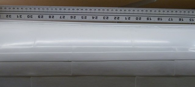
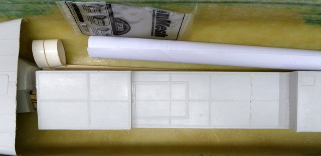
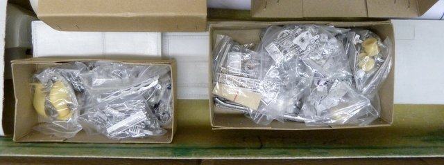
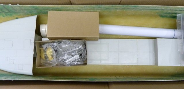
I am reoffering the St. Nectan kit. It was purchased in 2016 and unpacked to check contents. When I first offered the kit I didn't notice that there was a hull problem. There is a flaw in the keel. It is perfectly straight but sags about 1/8' to 1/4" in the middle (hogging). I checked with Mountfleet and this is a direct quote via email:
"Hi
They all have the same problem, our workshop boat also has one and as ours is sat on the shelf you can see it. I think it was obviously in the original plug.
it would probably be something that would be difficult to change Thanks Mountfleet models"
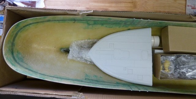
Otherwise the hull is perfectly straight. It still makes up into a beautiful model. With the bilge keels in place it will hardly be noticeable and will not affect the sailing.I have included a picture of the hull with a straight edge on it to show the problem. I have a lot more pictures of the hull and if interested I will be happy to send them via email. The hull is actually in excellent condition except for the hogging problem at the keel.
As a result of the hull problem I am asking $795 plus shipping. Shipping is about $120 - $140 to the North East Coast USA from 91307. The box is 71 x 14 x 12 and weighs 32 lbs.Thanks for looking.
- gieb8688 and GrandpaPhil
-
 2
2
-
Contact Mantua Model UK and ask them for the Sovereign assembly manuals. There probably be a charge. Hope this helps.
- marktiedens, md1400cs and mtaylor
-
3
-
eBay, S-38 Schnellboot Upgrades. I just searched S-38 Schnellboot Props. A very nice upgrade kit with motors, mounts, shafts, etc. It all installed very nicely once the prop shafts were lined up. Trying to implement the Lurssen effect was my downfall. I have run the boat for a while and then passed it on to an interested individual.
- mtaylor and Old Collingwood
-
2
-
-
Hi Chuck,
I just noticed that the parts for chapter 3 are already sold out. Will you have more available soon. I check the SYREN site regularly and I just must have missed it.
Thanks,
Iran
-
-
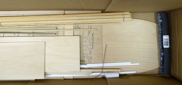
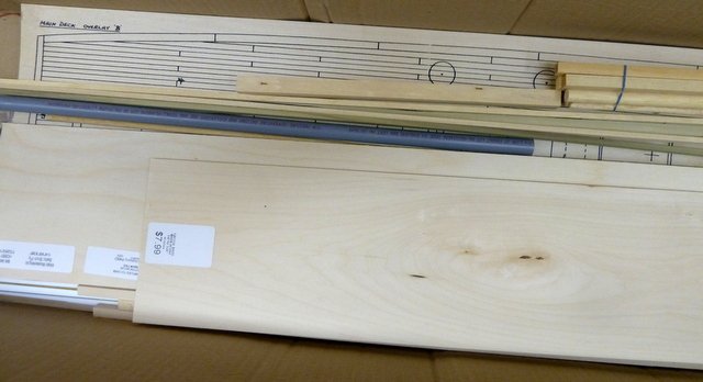
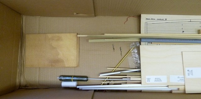
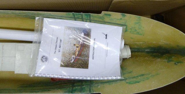
I have a Mountfleet St. Nectan Kit that unfortunately is much too large for my modest work shop and is a bit larger for both transportation and display. It is new from Mountfleet purchased 2016. I have a few MHB kits and the Winchelsea to build and the St. Nectan is just gathering dust. The kit is complete as shipped from Mountfleet. There are some very nice build threads on the net including Kevin's on MSW. I am asking $950 for the kit and I will be happy to split shipping costs. The box is quite large at 71 x 14 x 12 and weighs in at 32 lbs. I computed approximate shipping costs from 91307 to New York and it came out to around $140 but I have not computed it recently. It is the flagship of the Mountfleet line of kits and builds into a very impressive model.
If any interest in the kit, I will be very happy to supply some pictures of the contents but there is enough based an all the build threads and Mountfleet's website that details are readily accessible.
Thanks for looking.
-
Hi Chuck,
Just signed on and ordered Chapters 1, 2, frames. I swore I would not start another built up ship model but with your effort in developing the kit, I will fully enjoy the build.
Thanks,
Iran
- Ryland Craze, Chuck, Stuntflyer and 1 other
-
4
-
The new boiler is on order and will take about 12 weeks to get it built and sent from across the pond. In the mean time, when I get back I will be stripping the cabin and doing some rebuilding.
Until next time,
IR3
-
I commented in a previous post that I would show the steam plant installed. It would have been exactly as in the earlier model pictured above but after giving it a lot of thought, I am not going to use the B2F boiler. Being inside a confined space it needs to have as many safety items installed. While it is the suggested boiler for the Y2DR, it would be very difficult to add some safety features like a fuel regulator and shutoff valve and the throttle is very clumsy to manage. I am searching for a good source of boilers for this model and when I find what I need, I will post it. I need to start stripping the main cabin but that will start after the first of the year as 17 day vacation is coming up.
So Happy Holidays to all and
Until Next Time,
IR3
-
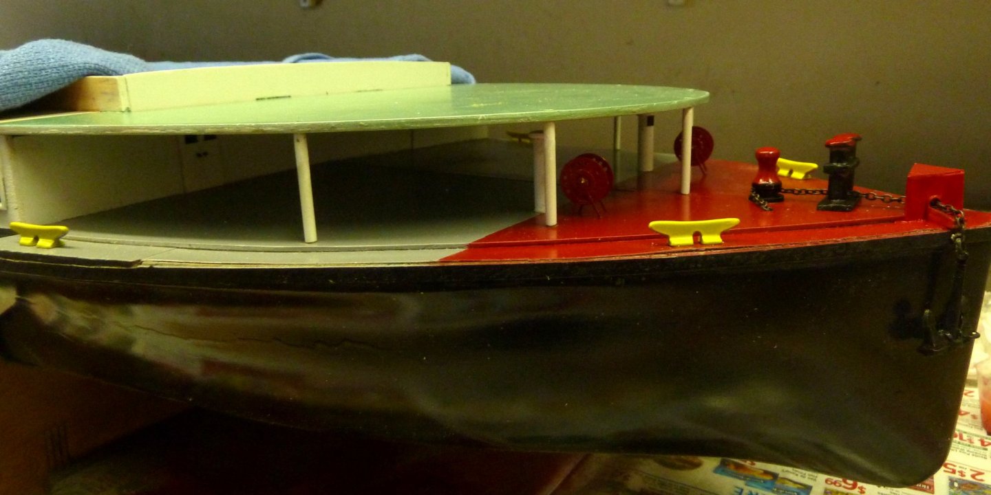
So this is about it for now on the foredeck. A lot different than earlier pictures above. The deck now has a steel look to it and the vents are under the second deck. The cleats are from the original kit. Since this is just a swimming pool boat, I just left them as they are. Not quite the same as the ones on the boat today. The reels need some string to resemble mooring lines. The derrick for the passenger ramp will come much later after the main cabin is refurbished. Next update will be with the steam plant and radio installed. I will show a picture of the main cabin as it is now just to show what a nightmare it will be to strip it and realign the parts.
Until next time,
Ir3
-
-
-
I have the complete set of The Fully Framed Model by David Antscherl and Greg Herbert including the Swan IV Sail Making Supplement. Volumes II, III, and IV are still in original shrink wrap. Volume I not shrink wrapped but like new. Asking $225 shipped CONUSA for the complete set only.
Thanks for looking.
I JUST FOUND THE PLANS SET. THE PLANS SET PLUS THE BOOKS IS $285 SHIPPED CONUSA. SO BOOKS $225, PLANS SET $60.
-
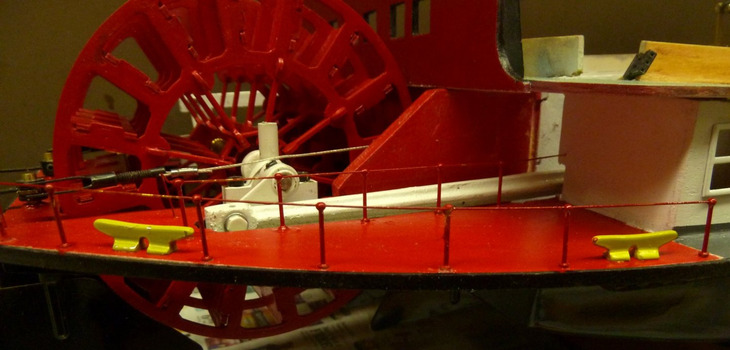
I spent some tome getting the Paddle Wheel area up to date. The railing stanchions from the kit are stamped out of sheet brass but I did manage to find a single ball stanchion 15mm high which is exactly the correct height. There is an opening in the aft bulkhead for the maintenance crew which I may simulate with a black door. This is just about it for the stern. I may add some miscellaneous stuff but that is TBD.
Next update will include detailing for fore deck.
Until next time,
IR3
BTW, some of the likes are going to my previous build (which I wish I never parted with!!!)
- GrandpaPhil and yvesvidal
-
2
-
This boat is gone. Turned over to another modeler to finish. But that is only part of the story. I really missed this boat. It should have stayed in the shop. Being a glutton for punishment, a basket case appeared on RCG but it had the complete steam plant for this boat, Y2DR, B2F, Burner, and Puke tank. So lock me up in a padded room but here goes.
The original owner purchased this kit in 1994. Being a very difficult kit, he was way over his head. I purchased this mess knowing a bit about how it goes together. I am just about finished with the hull and 1st deck. It will be rebuilt as near to current configuration. It will have a mixture of goodies so I place it around 2008+. I will add more pictures later as the rebuild goes on but the main feature is a replacement paddle wheel. The replacement just looks like it really belongs. You can compare it to an earlier picture.
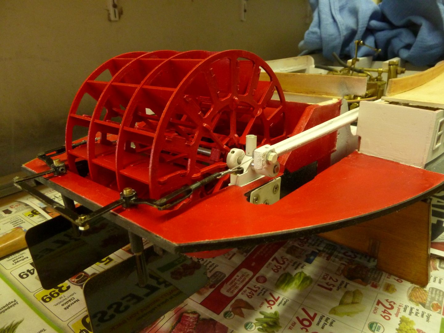
Next update from my Mental Ward!!
- mtaylor, J11 and GrandpaPhil
-
3
-
This item has been sold to a fellow modeler. Thanks for the interest and the comments.
-
-
-
Mark, thanks for the reply. My biggest problem is running across something interesting and different and I just have to do it. Like implementing the Lurssen effect on the Schnellboot. I am too quick to gobble up an old kit only to realize that getting the running gear and fitting kits will be almost impossible and so more improvising. The Schnellboot was an interesting adventure but started taking up too much precious time. I do have some very nice Steam projects that I have collected over the years and will concentrate on them. For sure, there will be no improvising on them, just straight forward builds with excellent instructions and steam plants designed directly for them. Time is moving on too quickly.
-
I have had so many problems getting the prop shafts to line up and getting the Lurssen effect working that I decided to just do a static build. I can see now what the kit manufacturers go through to engineer running gear in the models. It is above my pay grade. If anyone wants to try a motorized version of this, please let me know. I have all the components removed and may offer them. Thanks for the followers. When I get back to working on this, I will do more posting.
- Old Collingwood, mtaylor and lmagna
-
3
-
Yes, I do believe it will be quit fast.
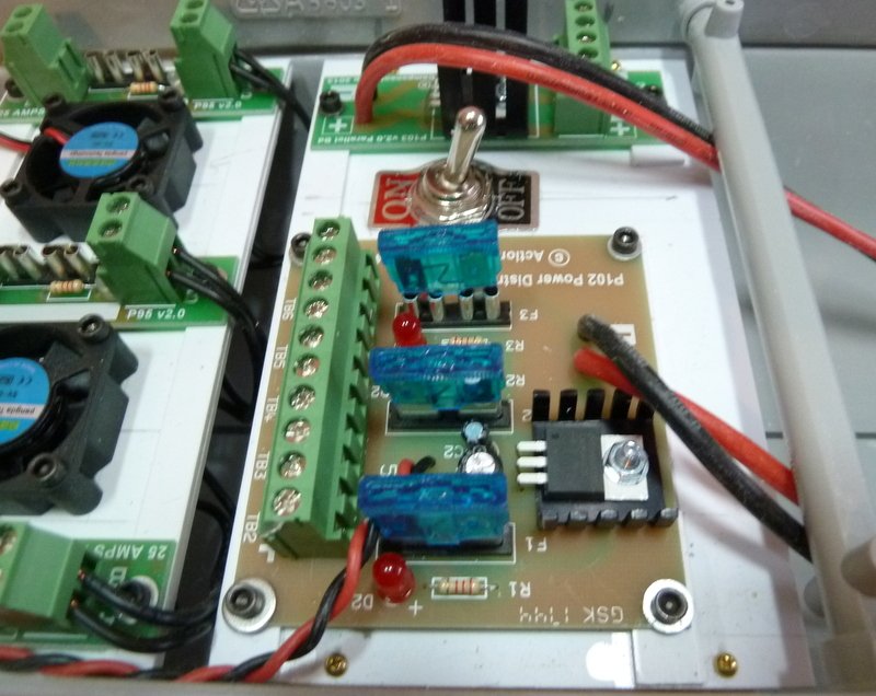
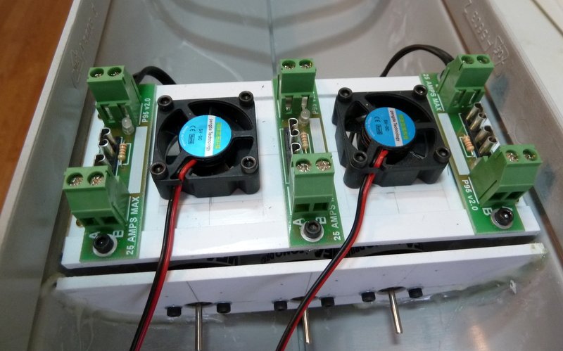
Electrics installation is just about done. The Power Distribution board, the Battery Combiner board and ON/OFF are installed. The switch is a Double Pole ON/OFF so instead of disconnecting batteries when done for the day, the switch will connect the positives of the batteries to the Battery Combiner. The Battery Combiner will run with just one Battery connected so depending on weight distribution I can run 1 or 2 batteries. When wiring the batteries, I might use a Deans 2 to 1 connecter so I can hook up the charger without taking out the batteries, TBD. The last of the installation will be a suitable location for the RX. I am still using my F-14 Marine radio running on 75MHZ. The RX position should not be a problem if kept away from the ESC's.
Until next time,
IR3
- BenF89, lmagna, Old Collingwood and 2 others
-
5
-
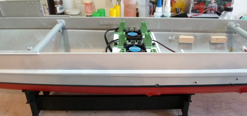
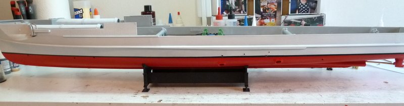
Once again, thanks for the likes and the comments. The hull has been painted and final installation of electronics and running gear has started. I absolutely hate painting so no micro close ups of this paint job. When I paint the model it comes from the shipyard with battle damage. If it came to a choice of painting or going to the dentist for a root canal, in the words of a famous old comedian, "I'm thinking about it". But, oh well, my goal is to have a reasonably acceptable model but testing of the Lurssen effect it on the top of the list. We will not be getting any closer to the model to check out the paint job.😀
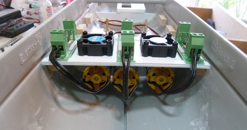
The motors are in as well as the fuse boards and fans. The motors are wired to the fuse boards. Nice to have all screw connections. The fuse/fan board fits nicely and has ample clearance to the deck. I think with the deck house on there will be enough openings to get some cooling air in. Also, some hatches will be open so hopefully some air will exhaust through them. I am not too worried.
Until next time,
IR3

- yvesvidal, GrandpaPhil, BenF89 and 4 others
-
7
-
Hi Mark,
There will be a few open hatches. Hopefully it will be enough. About the torpedoes, Merriman sold a torpedo kit for the 1/72 Revel Gato running on compressed CO2. I suppose that one could use the same system here but probably not. But, a very interesting question.
Thanks,
Iran
- mtaylor, lmagna and Old Collingwood
-
3


Mountfleet St. Nectan Kit -- SOLD --
in Traders, Dealers, Buying or Selling anything? - Discuss New Products and Ship Model Goodies here as well!!
Posted
Thanks for the comments on the kit. It is quite a challenge. There are several very good build threads on the net as well as on MSW so there will be lots of support.