


mattsayers148
-
Posts
685 -
Joined
-
Last visited
Content Type
Profiles
Forums
Gallery
Events
Posts posted by mattsayers148
-
-
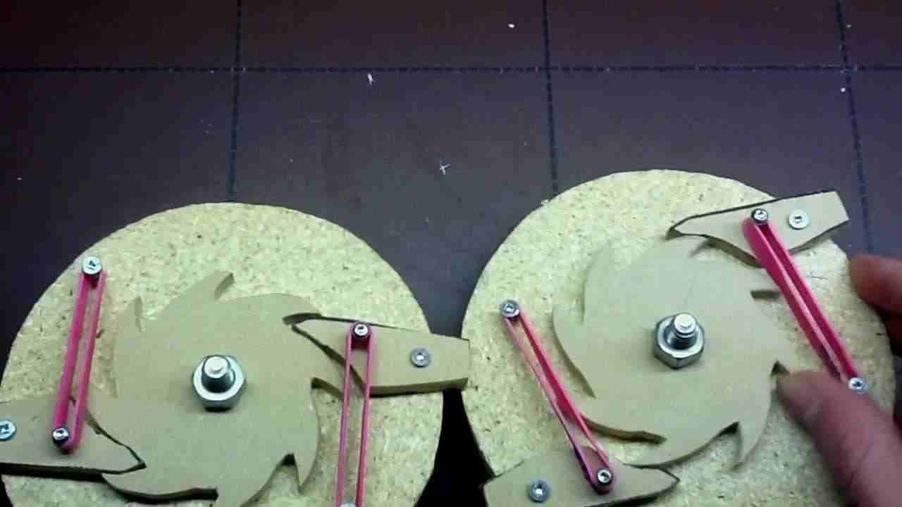
Or... Each side has a complete ratchet assembly, on side forward and the other side reversed. One side engaged, the other side free spinning.
- CaptainSteve and GLakie
-
 2
2
-
Since the winch was most likely used not too often, reversing makes sense.
- CaptainSteve and GLakie
-
2
-
-
-
Hey David,
Thank you for your positive words of encouragement. I have to share the positive input with those who help inspire me with their incredible abilities of craftsmanship and thinking outside the box.
Hey CaptainSteve,
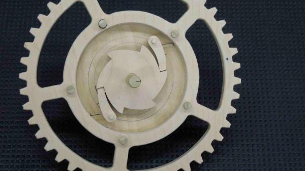
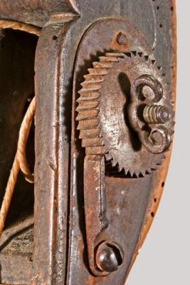
I spent a couple hours yesterday looking at hundreds of photos from the Royal Museums Greenwich for the ratchet mechanism. I found one small service vessel that I think is the answer. The photos were a little grainy but I could make out what appears to be like the first image with the two pawls on the top side opposing each other. The windlass also looked to be the same overall diameter as the gear itself. I'm trying to figure a way to get an image that is easier to see.
Matt
- CaptainSteve and GLakie
-
2
-
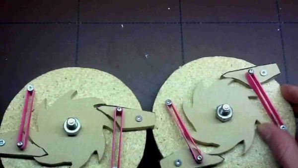
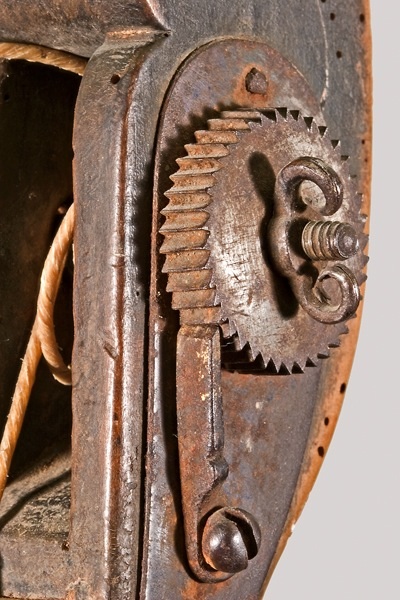
Well I found some pics of wooden ratchet and pawl assemblies.
- GLakie and CaptainSteve
-
2
-
Hey Buck,
Maybe Jim Baumann worked at Area 51?
Matt
-
Hey CaptainSteve,
That's an excellent solution. I though of cutting off the tips of the windlass and boring it out to fit iron bar with gear located flush to the winch holders, in line with the pawls.
Matt
- GLakie and CaptainSteve
-
2
-
Hope you feel better soon.
Matt
-
Hey CaptainSteve,
I think I understand that the wood itself was notched to be the gear. It seems though that the wood would be exposed to extreme pressure and, well splinter?
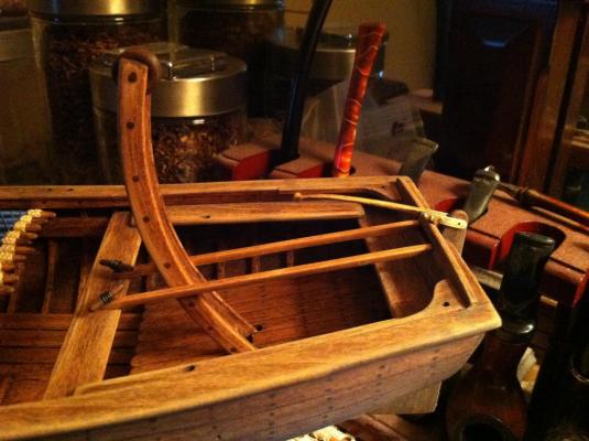
As a side note, I found a bounty launch model at Royal Museums Greenwich that shows davit(crane arm) lifted to an upright position with the tiller attached. I would assume tiller arm would be unshiped when winch was in use.
Matt
-
Hey CaptainSteve,
Thank you for your kind words on the oars, and thanks to you and all for the likes.
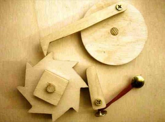
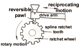
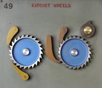
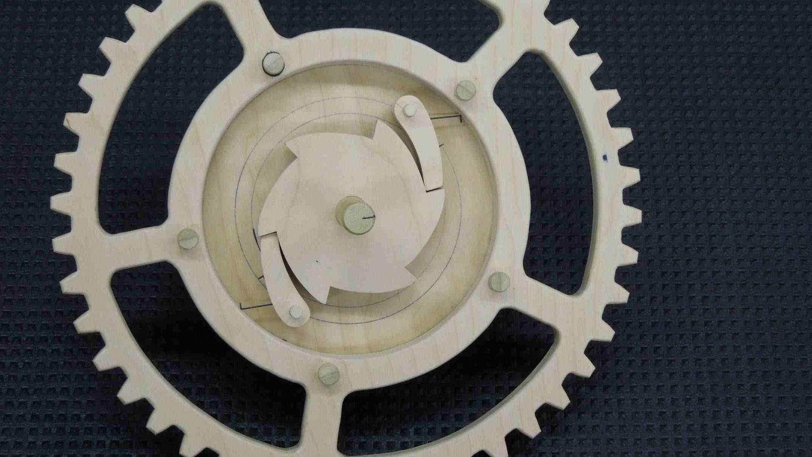
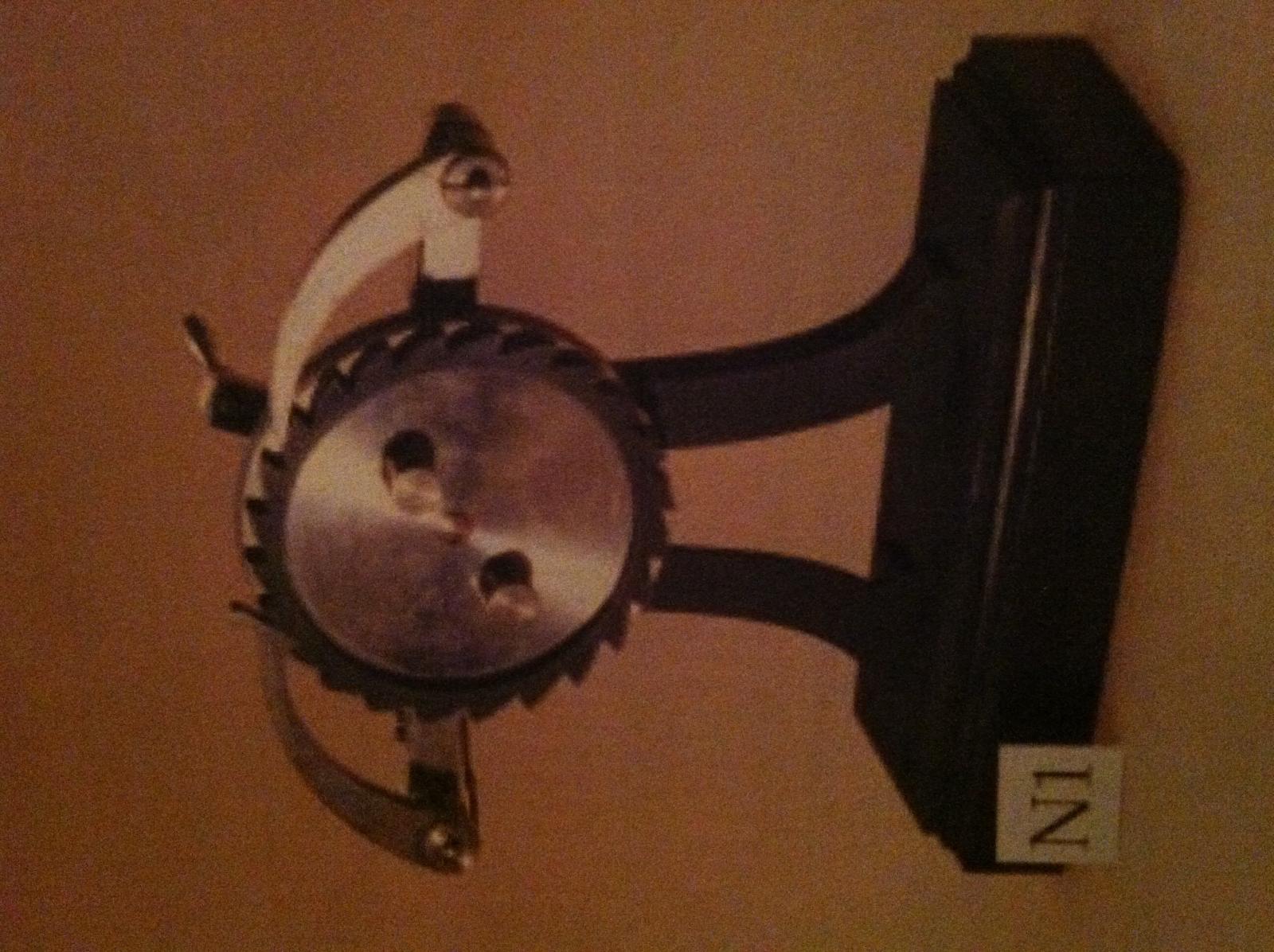
I had a much similar thought about placement of the ratchet wheel(cog). I'm also waiting for my gears to arrive. My thought was to replace the shaft ends of the windlass fitting both sides with a gear. I assume the four gears would be one up one down per side? I found this diagram that would require only one cog and one ratchet and pawl mechanism per side. However, would something like this be available or in use at that time?
The diagram looks to be used for, possibly, a two man pump action ratchet system. Hence the reciprocating arm. But could this be used in a fixed location?
Matt
-
-
Hey Buck,
Dang! The are so life like, and on a penny! My swelling went right down and I tuck my tail in defeat.
Matt
-
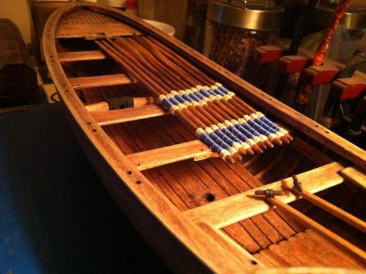
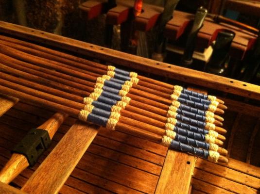
So I finally finished the oars...for now. I still need to get some contacts to test on the compass. I've got the masts shaped and trying out some different "aging" ideas.
This question goes out to everyone. I've been able to find lots of pics and diagrams of the ratchet and pawl mechanism, I just can't find an image or diagram of its proper placement on a small boat. So if anyone can find info on this can you point me in the right direction?
Thank you all in advance, I know a lot of you may hold the key to my conundrum.
- GLakie, GuntherMT, CaptainSteve and 2 others
-
5
-
-
Hey CaptainSteve,
Beautiful work on your grapnel! I wonder if there be any seaweed still on her?
Matt
- CaptainSteve, GLakie and JesseLee
-
3
-
"The rose compass was from Google Images, and I found that if I put the image into a Word document, I could shrink it way down with decent resolution by grabbing the corner of the image and making it tiny on the document itself before printing."
Hey Buck,
Thanks for the Google images tip. That worked perfect for mine. I'm pretty computer illiterate so I was able to print out the pics, then used the down-size option on my printer. Great tip!
Matt
-
Hey Buck,If you do decide about magnifiction, the Optivisor with a Quasar led light kit is pretty nice. This company also makes an Acuvisor, but the lenses are plastic where the Optivisor's are optical glass. The Optivisor is worth the extra cost for the for the clarity (I started with the Acuvisor). That is cool about your son. Let's get him going on a build log of his own!
BTW, my swollen head deflated as soon as I saw your compass' brass mounting! I wonder if I could pull that off at 1:25 scale...
Thanks for the info on the magnifiers. I have titanium implants in my ears, what about bionic eyes....eh, the Optivisor is probably much cheaper!
I'm sure with your super-vision 1:25 would definately work. I tried to keep the compass the same size as your 1:16 conversion, and just eye-balled the rest to look even. I was too afraid of seizing the whole thing up by soldering, so I carefully applied thin CA to the tips. Thanks for the compliment, now I'm stuck in my room again!
Matt
- GLakie and Salty Sea Dog
-
2
-
Matt,
I'd hate to be responsible for doing the squirrels out of a job, but no doubt you are aware that winches would require cogs and ratchets to operate ...

Will I ever be able to finish my homework CaptainSteve?
- GLakie and CaptainSteve
-
2
-
Thank you so much Buck, CaptainSteve, Keith and for all who liked my post. I need to build a neck brace to hold my bloated head up!
Keith, thanks for the congrats. Turns out my son is quite the thinker and tinker like his old man. I'm going to see if he wants to have a go at one of my models, I have a feeling he might put us all to shame.
CaptainSteve, thanks. I just bought 4.4 oz(123.2g) lot of steampunk gears, so some new ideas may still lay in waiting, I've been turning my wheels on a way to make a functional dial.
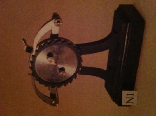
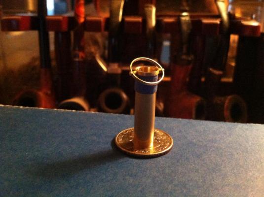
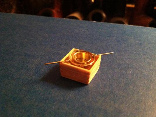
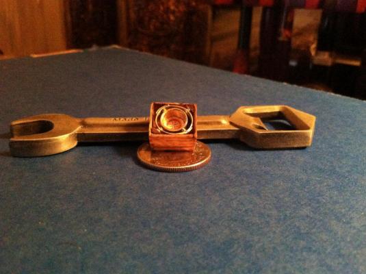
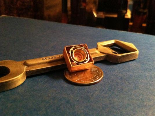
Buck, thanks to you for directional inspiration for the compass. Its not nearly as finite as yours. I broke a couple of the outer rings, the four holes weakens the ring so one false move and its do over. I had just bought myself a new dremel and a bit set 61-80, holy crap those bits are tiny. I'm still too stubborn to get a magnification instrument so if I go much smaller I may have to cave in. I was just happy that I was able to make the self-balancing ring functional. Now for a working dial and lens, they're still in the squirrel cage.
- CaptainSteve, GLakie and Salty Sea Dog
-
3
-
Thanks George,
I really appreciate input from everyone. There's so many great ideas flying around in here, it really gets the creative juices flowing! I really enjoy finding photos of period items and giving it a go at replicating them, or at least a fair rendition.
Matt
- GLakie and CaptainSteve
-
2
-
Hey Jerry,
Excellent progress on your build, it looks awesome. I haven't decided which of my builds I'll do next, but I'm leaning towards this one.
Matt
-
Hey CaptainSteve,
Well you've been a busy little beaver this week! I love the buckets. Now what be fillin' those buckets?
Matt
- CaptainSteve and GLakie
-
2
-
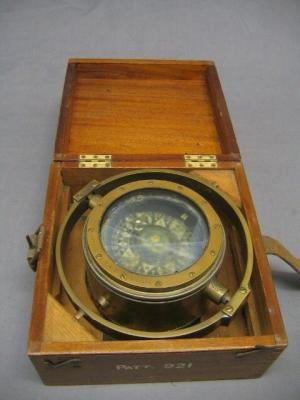
Well I got sidetracked this week. I finally got my son back after 6 years of separation. So we've been catching up while I dink away at my build.
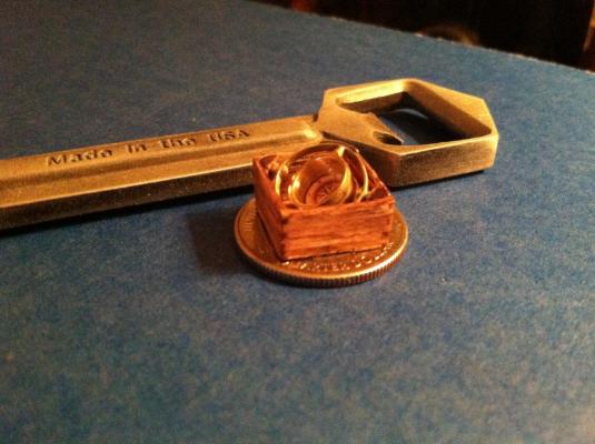
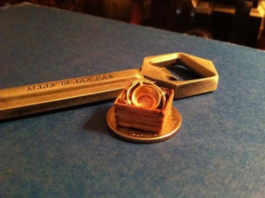
I saw this photo and thought it to be a nice looking compass. I'm not set on the face yet, and might be trying a contact for the lens. Still workin on the oars, they take more attention than conversations will allow. Those assorted metal pieces worked perfect for this application.
Matt
- IgorSky, GuntherMT, michael mott and 9 others
-
12


HMS Bounty Launch by mattsayers148 - FINISHED - Model Shipways - scale 1:16 - SMALL
in - Kit build logs for subjects built from 1751 - 1800
Posted
I'm trying to guide my attention towards my tool chest...again. I found this list by googling 18th century shipbuilding tools. This may help those who might wonder what could have been in the carpenters toolbox.
From Ralamb's Skeps Byggerij, 1691.
Trans. by J. Aasland, Jr., Hampton, Va.
Early Shipbuilding Tools used in Sweden and Other Countries
1—English Broad Axe. 2—Compass. 3—Compass with Chalk Holder. 4—Chalk Line on Roller. 5—Compass. 6—Axe for Holes. 7—Ruler. 8—Tongue on Ruler 1½ ft. 9—Dutch Ruler. 10—Tongue on Ruler for Ship layout. 11—Swedish Cutting Axe. 12—Trimming Hatchet. 13—Hook for removing old calking. 14—English Adz. 15—Adz. 16—Swedish or Dutch Adz. 17—English Handsaw. 18—Handsaw with Handle. 19—Mallet. 20—Hammer. 21—Claw Hammer. 22—Circle Saw. 23—Auger. 24—Dutch Brace Auger. 25—English Wood Chisel. 26—Wood Chisel. 27—English Mallet. 28—Gouge. 29—Swedish Mallet. 30—Gouge. 31—Gouge. 32—Gouge. 33—Calking Mallet. 34—Calking Tool. 35—Spike Iron. 36—Calking Tool. 37—Calking Mallet. 38—English Gouge. 39—Calking Iron. 40—Lubricating Tool, also for removing pitch. 41—Hook for removing oakum or old calking. 42—Calking Iron. 43—Calking Iron. 44—Tool used to clean out seams. 45—Calking Iron. 46—Calking Iron. 47—Scraper.