


Philg88
-
Posts
166 -
Joined
-
Last visited
Content Type
Profiles
Forums
Gallery
Events
Posts posted by Philg88
-
-
I seem to have spent most of the last week thinking about this build rather than actually doing anything. I've decided to go with LED lighting as I have a working circuit developed for the King of the Mississipi project and with a build of Victory's duration/complexity, I think it's worth the extra effort. This enhancement means that I need to run power wires up from a plinth through the hull to various points around the ship. I intend to use three lengths of 6mm brass tube to mount the ship on its plinth, one or two of which will conceal the power wires. My plan is to reinforce the (false) keel with ply liners either side of the 6 mm holes for the brass rod to provide support. M4 bolts inside the tubes will fix to nuts attached to points inside the ship, which have been hollowed out of the false keel. The entry points of the tubes will be hidden by the planking/copper and in a location pretty much hidden from sight once the build is finished. Can anyone, particularly fellow Billing Victory builders, think of any reason(s) why this might be a bad idea?
-
-
Thanks guys,
Yes, you're right Boyd, one of the ladders is the wrong way around. I'll correct the pic and reupload. Your build log really is an inspiration-although I'll be painting and trying to maintain authenticity, the natural wood look really is stunning. I'm afraid that I will have lots of questions so I hope you won't mind.
Cheers,
Philip
- shihawk, smokepole and Shipyard sid
-
 3
3
-
I've wanted to build the Victory for some time now and it is certainly the largest build I have attempted to date. I previously built the USS Constitution and a clipper whose name I forget and I have an AL King of Mississippi build in progress so I have some experience. All that of is course is no guarantee that things won't go horribly wrong at times!
These are the reference works I will be using, which is another way of saying that I may not follow the Billing instructions (if indeed that is possible given their chronic inadequacy)
*McKay, John (2000) The 100-Gun Ship Victory (Comprehensive line drawings of pretty much everything)
*Julier, Keith (2004) The New Period Ship Handbook (Has a whole chapter on building the Victory, albeit based on the Jokita kit)
*McCarthy, Ron (2001) Building Plank-on-Frame Ship Models (Useful general reference)
*Nepean Longridge, C (2012) The Anatomy of Nelson's Ships (An unbelievably detailed account of ships of Victory's class)
*Goodwin, Peter (2012) Haynes - HMS Victory. Owners' Workshop Manual (Tons of pictures plus other useful stuff)
... plus hundreds of photos gathered from the Web.
The idea is to complete the model as she stands in Portsmouth today, rather than at the time of construction, ready for Trafalgar, and so on.
I've modified one of my workbenches by fitting a rotating build cradle made of extruded aluminium. This allows the model to be spun around with minimal effort.
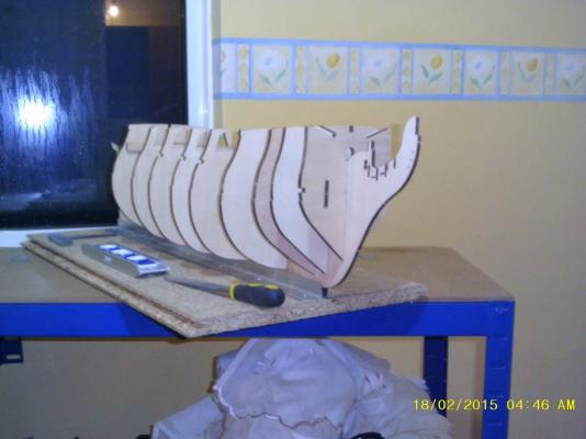
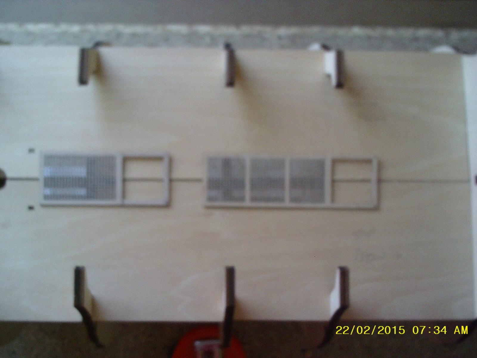
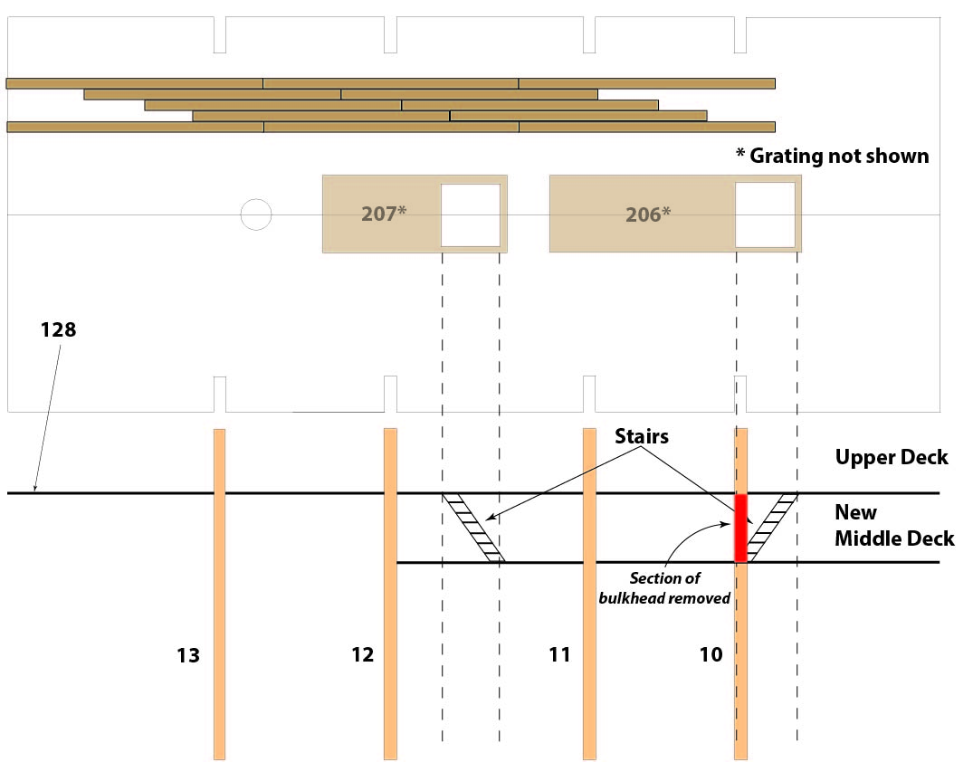
The first issue to resolve is the missing down staircases on the Upper Deck. Thanks to fellow forum member shihawk and his excellent build log for alerting me to the omission. I certainly don't intend to plank over where the hatches should be, as they will be visible through the skids from the quarterdeck. Instead I'm going to build two small sections of the middle (gun) deck to support the bottom of the staircases. I figure that it will be a lot easier to do now rather than later when space will be restricted.
This is how I intend to do it:
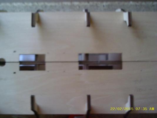

Please note: the diagram has been corrected subsequent to the original post such that the stairs are now the right way around.
-
Hi there Snoepert and glad to hear you're enjoying the build. It's certainly a bit different from the period ships that I've built in the past but nevertheless immensely enjoyable. The only two things I'd warn about so far are: 1) check that the 1st deck slots are in the right place for the buildings as they don't line up "out of the box". 2) Do the necessary preparation on the hull/knightheads to accommodate the "sternpost" before planking the hull.
Cheers,
Philip
-
Here is a pic of my Wallace and Gromit inspired Plank-o-Bend (with a nod to Ron McCarthy and his book Building Plank on Frame Ship Models where I first saw the idea). Just an empty can and a candle really-it works really well once you get the hang of it. The trick seems to be to "roll" the plank across the hot surface whilst applying forward pressure. The knurled handle of a craft knife seems the ideal tool for the pushing, but the can gets red hot so mind your fingers if you try this!
Plank-o-Bend
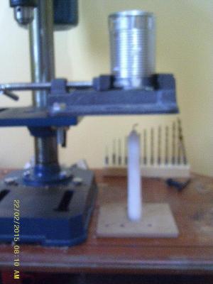
Bow rubbing fender curved using this method

- Grey seal, GuntherMT and CaptainSteve
-
3
-
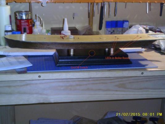
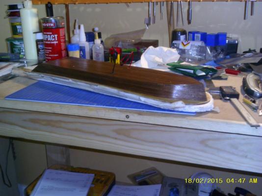
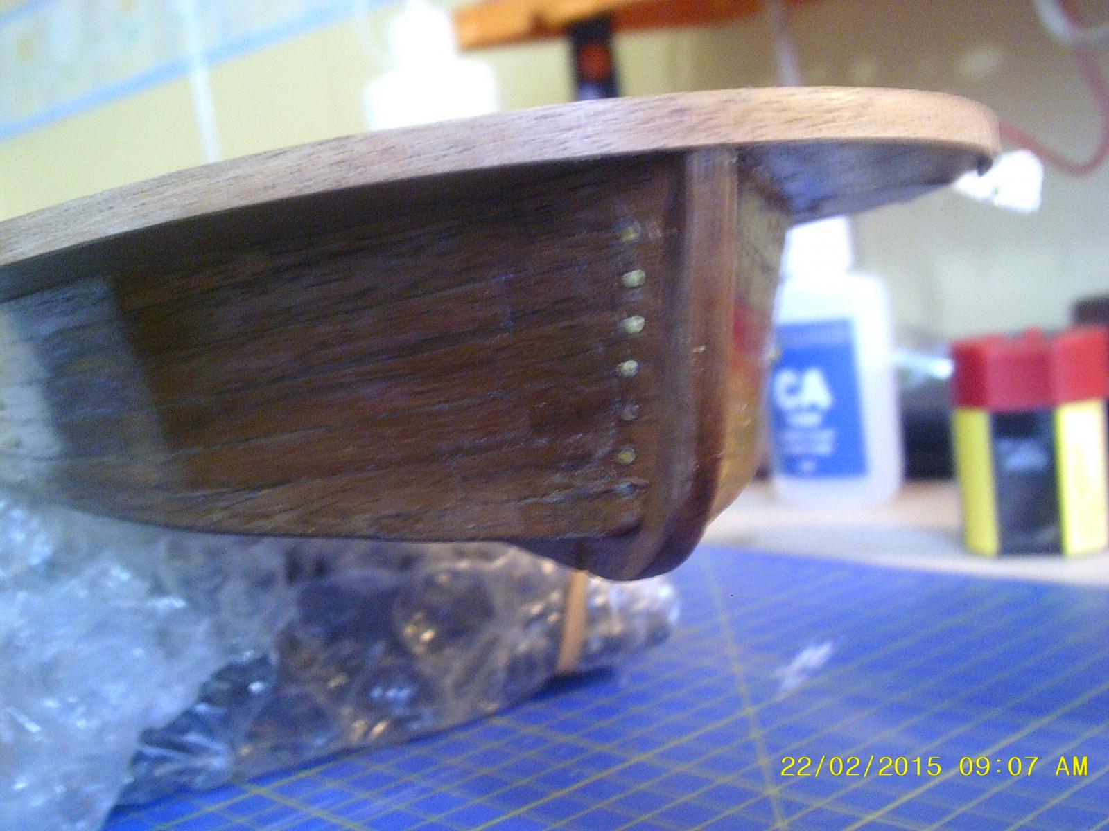
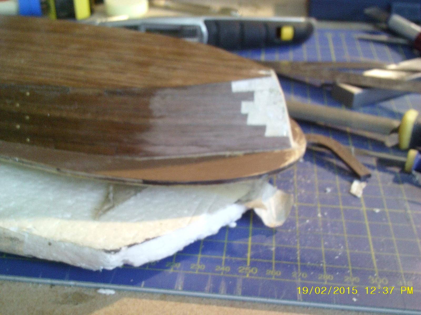
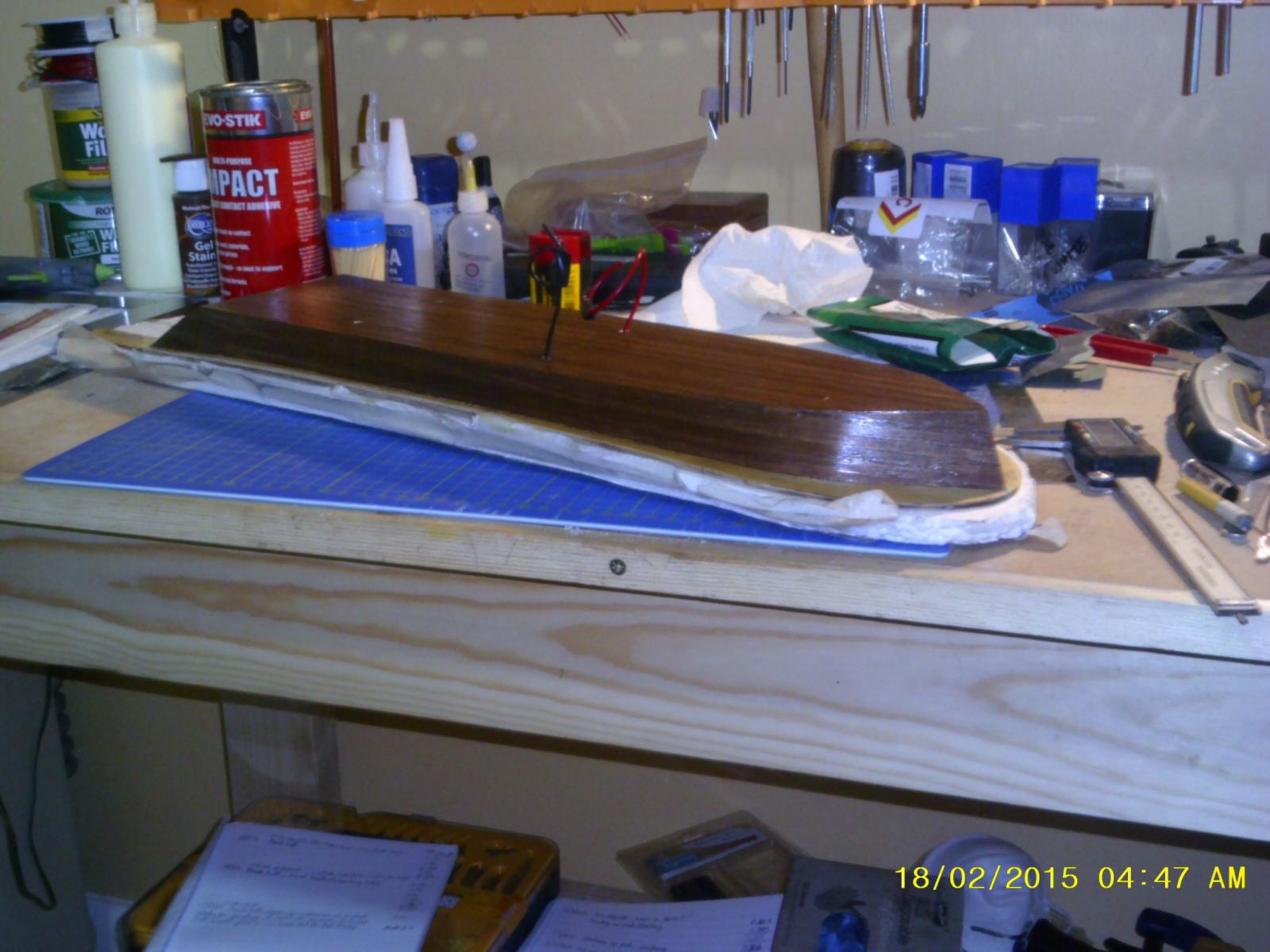
OK, back on track. Prow issue resolved so next will be the rubbing fenders and the engine/boiler room. Here are a couple of before and after pics of the repair plus the hull mounted on its plinth. The on/off switch is hidden in the shadow underneath the hull, which is deliberate.
Before:
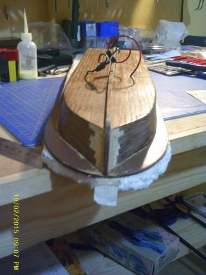
After:
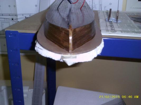
Mounted on the plinth:
-
Thanks KeithW,
I've replanked one side ... another three hours or so and the other one will be done ... a lot of extra work but that's all part of the challenge. Pics to follow.
-
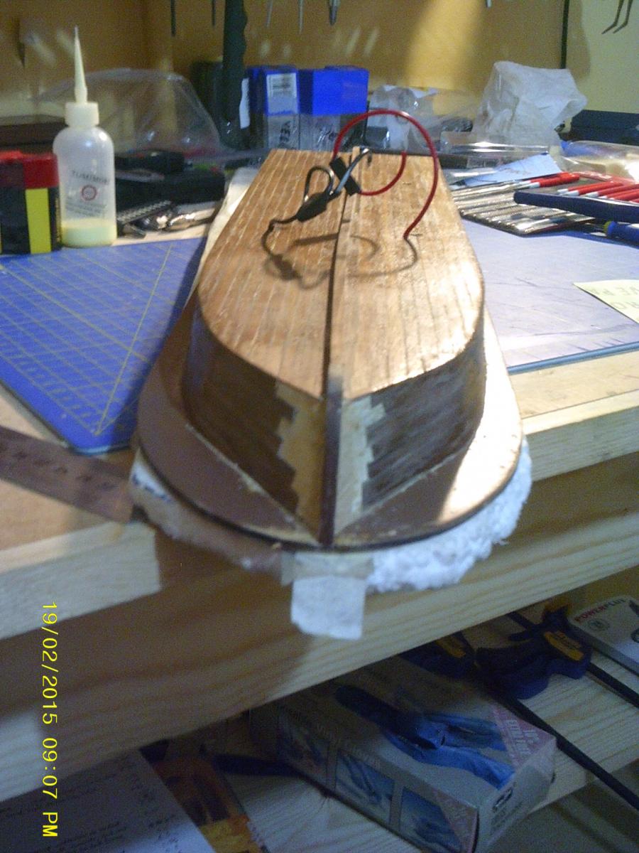
Alas, hit a bit of a speed bump today when fitting what AL call the "sternpost". The prow needed complete reshaping to fit it, which damaged the planking. I've spent hours stripping the planks back as far as I dare as I only have 370 mm of African Walnut left to reinstate them once the sternpost and keel are fitted. I could blame the instructions, which say to plank the hull before fitting the sternpost, but I really should know better based on experience.

-
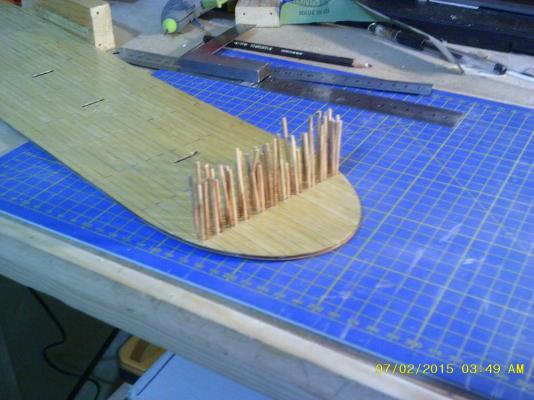
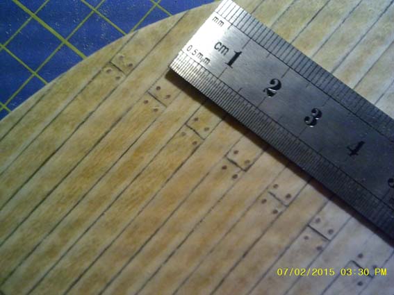
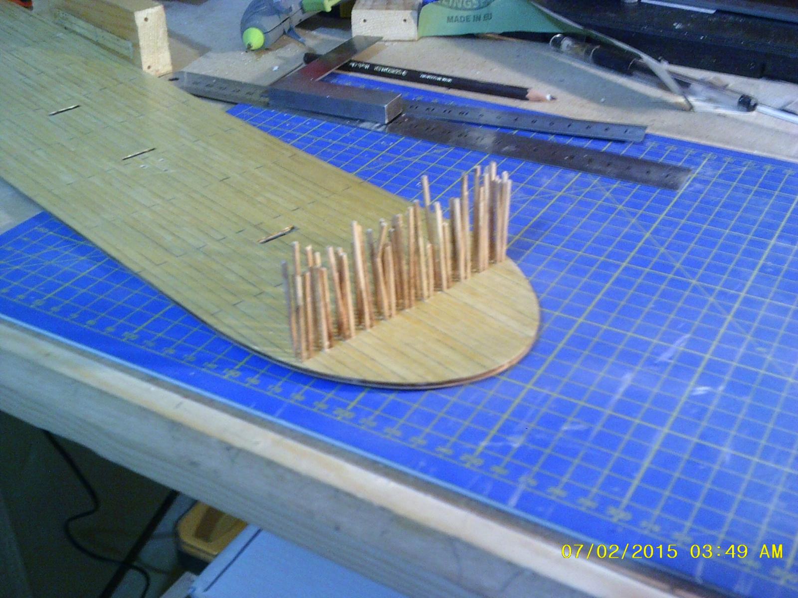
Nothing fancy inside the plinth - just the battery, a switch and the power feed that goes up to the hull. The side pulls off for battery access and is secured with magnetic strip to avoid the need for screws or a catch of some sort. Also a picture of the trenails - I like the dyed toothpick method, more work but I think it gives better definition than using a pen/pencil to simulate.
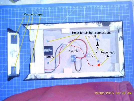
 .
.- Keith_W, CaptainSteve, GuntherMT and 1 other
-
4
-
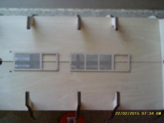
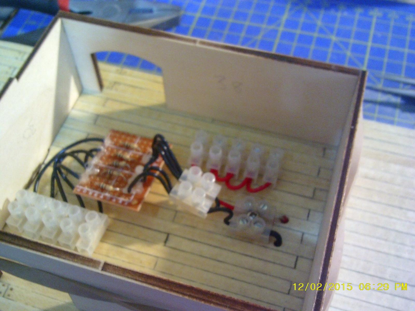
This is the power distribution board in the boiler room (see previous post) and details on how I did the treenailing. The ends of the cocktail sticks were stained with walnut to give more contrast, inserted into pre-drilled 0.7 mm diameter holes with a dab of white glue then snipped off level with the deck.

-
It's about 25 years since I last built a model ship so time for a new one, or in actual fact two - I will be doing a concurrent build of Billing Boats' HMS Victory 1:75 scale - this will be covered in a separate build log.
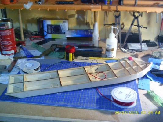
OK, back to the plot ... My plan is to have yellow LED lighting in the buildings on all three decks and in the pilot house then red/green navigation lights at the prow. Power comes from a 9V battery concealed in a plinth I build from MDF and standard moulding. The wiring comes up through a pillar from the plinth, passes through the hull and 1st deck then connects to a distribution board in the boiler room on the 1st deck. I calculated that a 100 Ohm resistor will handle 4 x 2.2V/20Ma LEDS and with these in parallel the distribution board supports up to 20 LEDs (5 x 4). I have tested it with 16 LEDs (14yellow, 1 red, 1 green) and it works fine so 20 should be no problem.
Now some pics, I need to figure out how to post these with individual commentaries but for now the descriptions are in the file names.
- CaptainSteve, Adrieke, Keith_W and 1 other
-
4
-
I didn't stain the hull - the wood looked good just as it was. I used three coats of matt varnish on the hull and first deck with a light sanding with P2000 grade emery paper before the last coat.
-
Hi there,
My first post and hopefully the first of many. I started this kit about a week ago and will create a build log before too long. The hull is certainly time consuming - the instructions are sparse to say the least and trying to figure out the stern took me a while. Look forward to seeing your progress.
Cheers,
Philip


King of the Mississippi by Philg88 - FINISHED - Artesania Latina - Scale 1:80 - with internal and navigation LED lighting
in - Kit build logs for subjects built from 1851 - 1900
Posted · Edited by Philg88
Work is in progress on the 1st deck buildings with no major show stoppers. I used contact adhesive throughout (except to fix the stabling boxes where I used white glue) and managed to avoid getting any on the face of the planks by applying very sparingly. One observation though, the AL parts list is wrong as it lists the stabling box ends (part no 37) as 4mm long and as far as I can see these have to be 7mm to fit. The passengers have arrived from Germany (cost around 11 euros including shipping), they now need their bases ground off and a shiny paint job ...