Cathead
-
Posts
3,526 -
Joined
-
Last visited
Content Type
Profiles
Forums
Gallery
Events
Everything posted by Cathead
-
 Glenn, by the time you're done, we're all going to have exhausted our vocabulary and be reduced to grunting and throwing bananas in an approving manner.
- 701 replies
-
- 10
-

-
That is so freakin' cool! I agree with Greg, I keep expecting to see it leap into action.
-
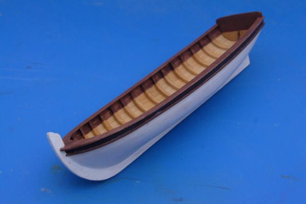
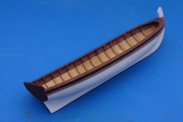
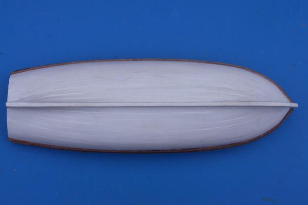
And here's the finished hull: I'm pleased with how it came out. This weekend I'll be working on the interior floors and other details.

- 64 replies
-
- 12
-
-
- 18th century longboat
- model shipways
- (and 1 more)
-
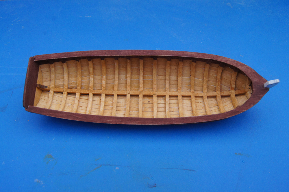
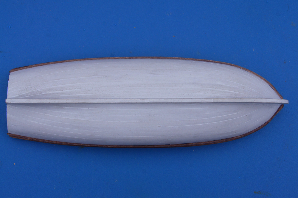
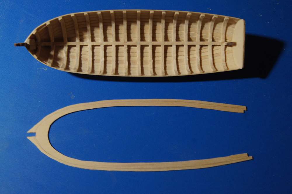
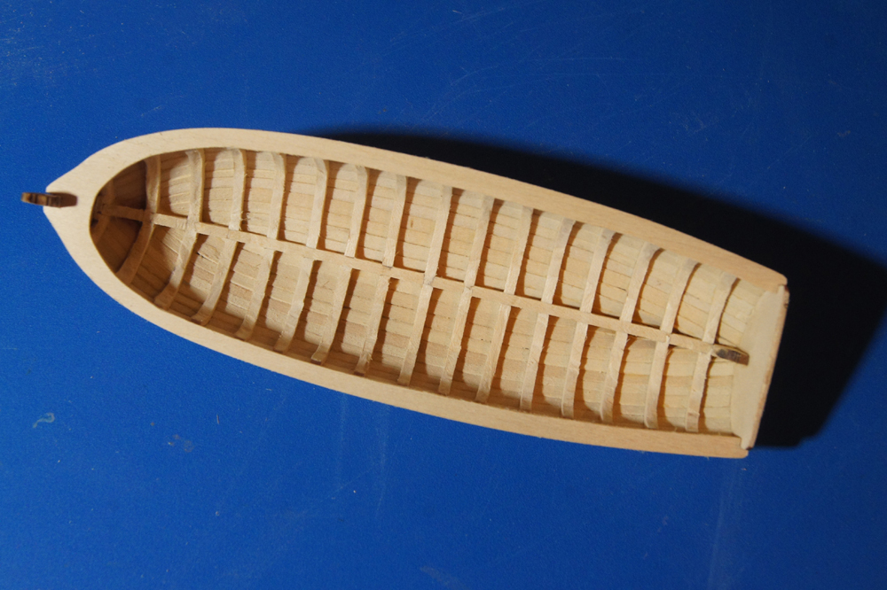
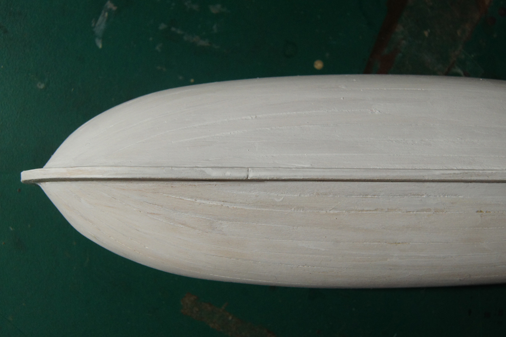
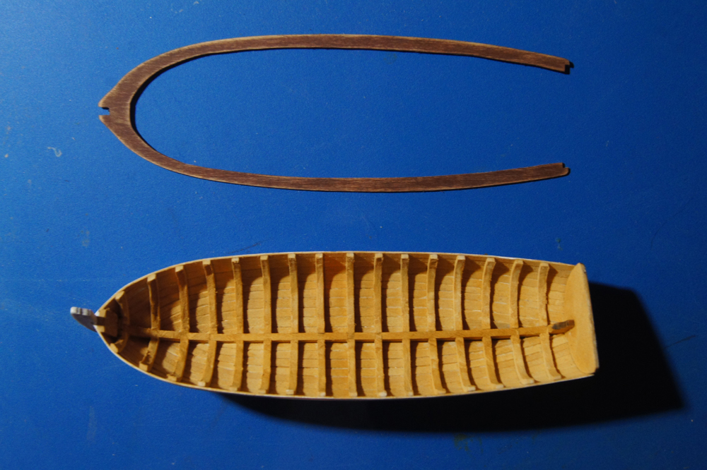
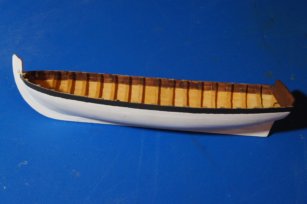
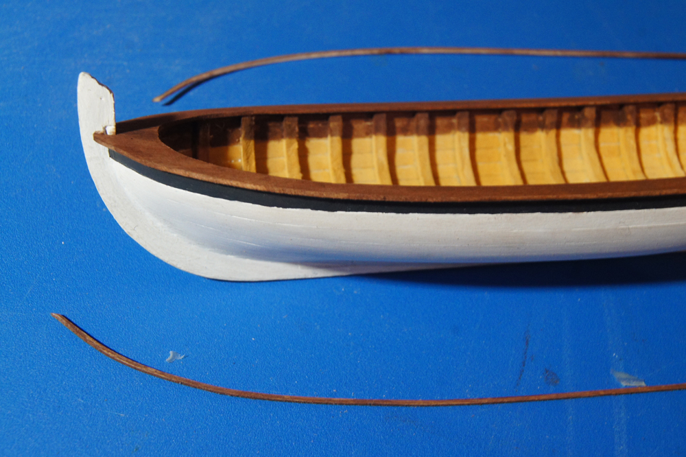
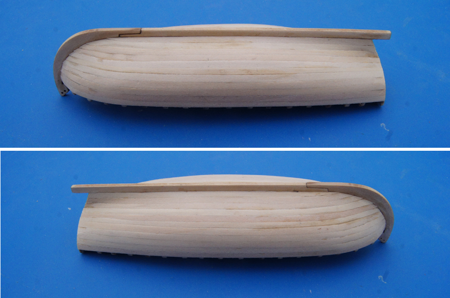
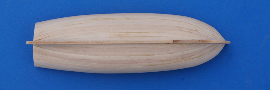
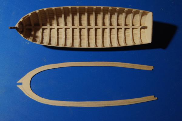
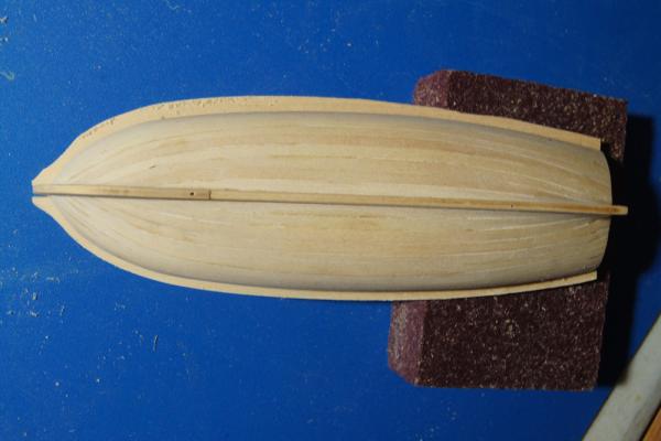
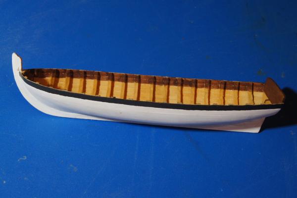
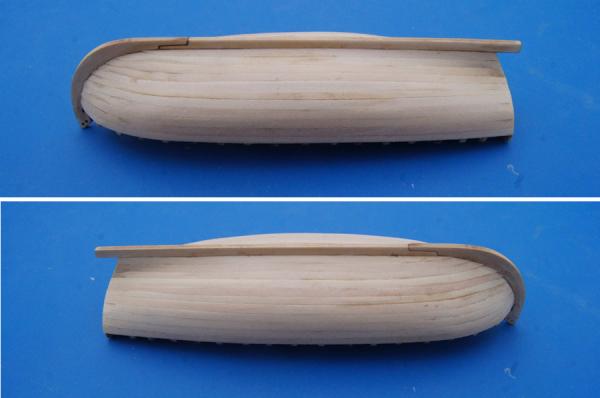
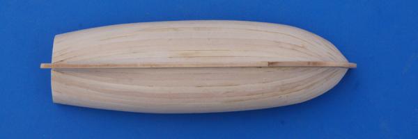
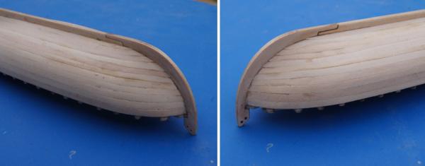
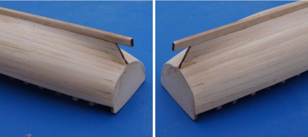
I chose the all-white hull. It was Mrs Cathead's first choice and my second, and it does give me a very unique model. As this is different than most approaches to this kit, I decided to document my work more thoroughly. Here's a step-by-step tour of the week's work: I hollowed out the hull using a motor tool. This was nerve-wracking at times, but I avoided any slips. I finished the inside with a rounded sanding tool I made: a short length of dowel, with a screw inserted for a handle to make a T-shape, and sandpaper attached to the dowel with double-sided tape. I adapted this approach from another build log, but am ashamed to say I can't remember which. I also decided to make the cap rail a single piece, rather than two. So I held the hull against a sheet of 1/32" wood and traced the outer hull, then traced a parallel edge in both directions. After cutting it out, I ended up with the fat piece you see, with the center line for orienting it properly. Here I departed from the kit instructions, which say to glue the cap rail in place before finish-sanding it. I did not do this, as my paint scheme involves using white and black paint, and two shades of stain, in very close proximity to one another. So I made a point of finishing and coloring the cap rail and moulding strip before attaching them. In the photos above, I'm carefully holding the cap rail in place while sanding it to shape. A lightweight rubber band near the stern helped with this. I wanted the hull white, but not with a thick coat of paint that would obscure the planking. So after one more round of finish-sanding, I applied a thin coat of white primer, using a cotton swab, which I feel gives more even coverage than a brush. When this dried, I sanded it with very fine paper, then added another thin layer of primer. In the photo above, the starboard (lower) side has only the first layer, while the port (upper) side has both. I think you can see that the first layer still showed some wood color through, while the second coat gave it a true white color while still preserving the run of planking. I like how this came out; my less-than-perfect planking job was also a benefit here, giving just a little extra texture to show through the paint. With the outer hull painted, I stained the inner hull with a diluted oak (all paints/stains used are Model Shipways brand), and the cap rail with a diluted cherry. I intentionally kept the inner stain slightly ragged, as I think it adds a more realistic level of texture to the hull's appearance. In a close-up photo it looks spotty, but in person it provides some visual texture that I find preferable in a lot of my models (I think the eye sometimes perceives perfection as false). I sanded the cap rail more than is shown here, removing most of the stain, before re-staining it and lightly sanding again. This gave the final surface a more complex appearance than solid color (note: I did the second staining of the upper surface after gluing it on, as described below). I then painted the sheer strake black, and stained the inner, upper two planks and the transom with diluted cherry. In retrospect, I wish I'd thought to NOT prime and paint the sheer strake, as the black over white made it too smooth and shiny; I'd have liked the black to soak into the wood more. But the final result is ok, as the cherry strips on either side help obscure that effect. I did the black freehand, without mask, following the plank's edge. I knew that the moulding strip would cover up any slight wavers on my part. This stage also shows why I left the cap rail off; it was much easier to do both of these jobs without it. I glued on the cap rail, did any final touch-up sanding of the top and sides, then re-stained it with more diluted cherry. I pre-bent the 1/32 square moulding strips by soaking them and clamping them to the hull (I did this before attaching the cap rail), then stained and sanded them. At this point they were easy to glue on, with some careful adjustment to try to get a smooth run parallel to the cap rail. In the next post I'll share photos of the final effect; otherwise I'll go over the image limit for a single post.


- 64 replies
-
- 8
-
-
- 18th century longboat
- model shipways
- (and 1 more)
-
Great details, Kurt! One question: do you know when tar paper came into use that way, and what (if anything) was used on upper decks before that? Apologies for my wordy theorizing. Should've just let an expert answer in the first place. Keep up the good work, Clarence, this has been fun to follow.
-
It occurs to me that another benefit of a canvas-type covering would be better traction. A lot of these upper decks didn't have much in the way of railings, and wooden decks can get slippery fast. What I don't know, even if this is the case, is when and where such things came into use. Most steamboat photography comes from the post-ACW era, so it's possible it's a later innovation that something like Bertrand didn't have. That would still make it relevant for Clarence's build. Here's an example; scroll down to see a zoomed-in view of the deck: http://www.shorpy.com/node/8708 The discussion thread mentions the rows of buckets hanging from a rack, wondering if they're tar buckets.That upper surface sure looks smoother than raw planking. It's also a very late image, though,1910, so there may be a new approach that wasn't available to earlier boats before the common photography era.
-
Clarence, great question, and one I wrestled with on Bertrand, too. I haven't been able to find any direct reference to how upper decks were finished, books just seem to pass over that question. This may be because superstructures are so rarely preserved, and contemporary chroniclers may have found the detail too mundane to record. There are also relatively few photographs of steamboats from a high enough angle to show the upper deck surfaces, and of high enough quality and zoom that you can see anything even when the angle is right. That being said, my sense after studying the images I could find, was that many of these exposed upper decks seemed smoother and more seamless than a straightforward plank deck. And in a few cases I could convince myself that the surface looked almost rumpled. They also seem a different shade of color (grey in the photos) than the lower plank decks. I think Carl's right that it couldn't be tar, because the heat of the Mississippi Valley would reduce that to utter awfulness. But I wonder whether they stretched canvas or some other covering over the planked upper decks? Or some kind of dry tarpaper, if that existed then? This could have helped protect the decks and provided some additional waterproofing, as I don't know how much time steamboat crews really spent caulking and recaulking deck seams. It wasn't the Royal Navy, after all, and a canvas deck covering would have been a lot easier than perfect deck maintenance. A quick glance at Model-Expo's Chaperon model appears to show a smooth black coating, as does the large-scale Bertrand model at its museum, though I'm not sure what material either represents, or what information that choice is based on. That being said, I haven't been able to prove it either way to my satisfaction, so went the safe route with Bertrand and just planked the decks. As a compromise, I stained the upper deck planks grey-black. This provided some attractive contrast with the decks below, and suggested the color change I thought I saw in photographs. I decided that I didn't want to try to simulate some kind of tarpaper/canvas deck covering without more information, so this was a safe approach, as no one really knows what the Bertrand looked like up top anyway. You might considering PMing Glenn Grieco to see if he has any insight, given his own extensive knowledge and connections to steamboat researchers. Same for Kurt Van Dahm, who is a big riverboat aficionado. Or start a question thread in the research section of MSW to crowd-source ideas about deck coverings. That might be the best approach, actually. Here's what I did to Bertrand, as a reminder: Sorry to not be much help; I'm just an amateur and there's likely more information out there that I haven't run across in my dabbling.
-
Steamboat deck nomenclature is definitely not intuitive.
-
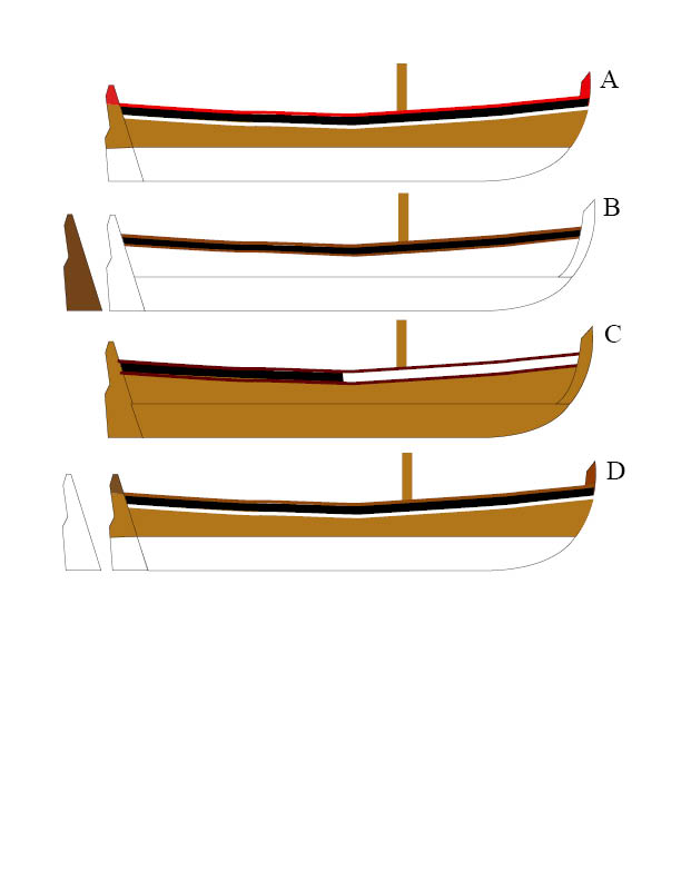
So I mocked up examples of four possible paint schemes, partly to get Mrs. Cathead's input since she'll have to look at the finished version, and partly to see if any of you had input. A. is essentially the kit plan, with a black stripe replacing the friezes. B. is the "Victory yawl" pattern I've found various photos of, using a black stripe and stained-wood cap rail and moulding strip. C. is an all-wood version using either a black or white stripe replacing the friezes D. is A but with stained wood replacing red on the cap rail. There are a few alternate rudder possibilities as well. I know which one I favor personally, but are there reasons for or against any of these, whether authenticity, feasibility, or other? Finally, I've never done treenails before. Is it worth doing them in areas that would be painted (like below the waterline)? Would they show through the paint on the real thing?

- 64 replies
-
- 9
-
-
- 18th century longboat
- model shipways
- (and 1 more)
-
Hey there, I just noticed this log and am sad to have missed it before. Looks like we were both building steamboats in a similar time period. Early on, you discussed using mouldings along the base of the cabin walls, wondering if that was something real steamboats had. It was, at least for the Bertrand (my build). When the boat was excavated in the 1970s, the entire superstructure was gone, but they were able to reconstruct the outline of the main structures by the 1/4 round moulding left nailed to the main deck around the perimeter of the structures. Nice job on the model!
- 65 replies
-
- 1
-
-
- artesania latina
- king of the mississippi
- (and 1 more)
-
Battle Scars
Cathead replied to tradewinds's topic in Painting, finishing and weathering products and techniques
If you're thinking of doing this in plastic, I recall someone writing an article in Model Railroader magazine an article about modelling damaged railroad cars. He had some fun techniques for bending and twisting plastic car bodies to simulate wrecked metal; for example I believe he used a hot flat-head screwdriver to gently warp the plastic inward, and so on. Certainly a number of model railroaders like to feature wrecks or other damage as part of their scenery. Perhaps a search of MR archives or other model railroad resources would help generate some techniques for modelling damage. I suspect you could use similar techniques for "damaging" plastic ship models, distressing them further with knife and rasp to make the final result more wood-like. If nothing else, buy a cheap kit or some scrap styrene, mock up a few test pieces, and experiment. -
Interesting. So the buckets were one wide plank, with one U-bolt per spoke. In comparison, both Bertrand and Arabia had two parallel planks, each with two U-bolts per spoke, like this: Arabia: http://janetbtaylor.com/wp-content/uploads/2010/10/arabia4.jpg?w=300 Bertrand (my model): http://modelshipworld.com/index.php/topic/10356-steamboat-bertrand-by-cathead-187-wooden-missouri-river-sternwheeler/page-7#entry344717 Bertrand (as displayed at the museum): http://modelshipworld.com/index.php/topic/10356-steamboat-bertrand-by-cathead-187-wooden-missouri-river-sternwheeler/page-7#entry348901 These two also don't have any reinforcing planks, just the bucket planks, which appear narrower in Arabia and Bertrand than in Heroine, though I can't tell for sure. Your reinforcing plank is 14" wide, which makes the bucket plank a bit wider still, while the others look like 12" or less to my eyes. But the overall bucket would be wider on both the later boats, given the double planks. Any theories on these differences in wheel configuration? Is it just that Heroine is a smaller boat and so used a simple one-plank paddle? Or was there an evolution to broader, two-plank paddles as being preferable? EDIT: additional question: what's the diameter of Heroine's wheel overall, compared to the width of the bucket? On Bertrand, the wheel was estimated at 18' diameter, with each bucket about 2' wide overall. My eye feels like Heroine has a different ratio, but measurements will tell if I'm off. Also, looking back at my Bertrand wheel, it hit me that I never finished one important detail: the U-bolts on the buckets! I'd meant to draw them in with a fine marker, as I didn't think I could get them right with wire at 1:87, but apparently never did and never noticed. Luckily the wheel turns, so I can still do it without too much fuss. Embarrassing.
-
Hey, Toni, me too! I appreciate your taking the time to provide feedback, it definitely made me go measure and check what I'd been doing. I've been giving some thought to the final appearance of the model, as it's about to affect how I proceed. There are two changes I'd like to make: to add sails, and to use a different color scheme. I'm just not a fan, personally, of the ornate friezes and don't think they'd look right on a model displayed in my very wood-heavy, non-ornate house. I like very laid-back models and the kit version is just too "loud" (not a criticism of Chuck or the kit, just a personal quirk). So I'm considering alternative approaches. I did some image research on other styles of longboats, and like the color scheme of the longboats from HMS Victory and similar approaches, like these: http://i2.wp.com/intheboatshed.net/wp-content/uploads/2008/10/victory-yawl-3.jpg http://www.blogstaugustinelighthouse.org/blog/longboat%20fullsize.jpg http://4.bp.blogspot.com/-IlVDIgPQXMo/VCgqFHskLPI/AAAAAAAAGD4/oqRiBjTLU4k/s1600/long-boat-peter-rindlisbacher.jpg I particularly like the idea of using a black stripe to replace the friezes, as an understated way of highlighting that upper strake. What I'm considering doing, is staining the hull and seeing how it comes out. If it looks good, I'll leave it at least partly as wood, otherwise I'll go all-white. So it could be one of these approaches: 1) All-wood, different stain on cap rail & molding strip 2) All-wood, black upper strake, different stain on cap rail & molding strip 3) White under water, wood above, black upper strake 4) All white, black upper strake, wood highlights (like second link above) For any of these, there's also the question of whether the red caprail and highlights still makes sense, or whether to stick with the white/black/wood scheme shown in all the photos linked above. Any thoughts? Should I put together some diagrams? I need to decide this, as it will affect the way I move forward on the cap rail and other hull finishing. Thanks for any input.
- 64 replies
-
- 5
-
-
- 18th century longboat
- model shipways
- (and 1 more)
-
You must be a great first date. My best planking effort is the equivalent of sweat pants and stubble.
-
That's probably where I got the idea from; makes more sense than thinking of it myself!
- 64 replies
-
- 4
-
-
- 18th century longboat
- model shipways
- (and 1 more)
-
I'm definitely afraid of sanding right through a plank, especially at one of the less-good joints where the planks are already slightly angled to one another, but I suspect you're right that I can go farther. I guess holding it up to the light could help judge plank thickness.
- 64 replies
-
- 5
-
-
- 18th century longboat
- model shipways
- (and 1 more)
-
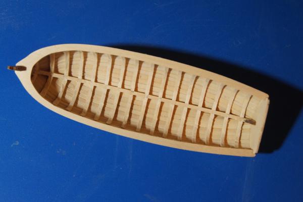
Here's the completed hull, for comment and critique. The flaws I see include some divots (resulting from clamping wet & soft wood while bending), and some plank edges that don't quite line up due to my less-than-perfect bending. What do you see? After a first sanding, it's reasonably smooth and seems like the faults will fade with painting and finishing. I think the port side is better than the starboard side; the strakes are more evenly spaced. I'd like to do a better job on my next planking task, but feel that this is acceptable as a learning experience. Also, after being so careful not to break the stem throughout the planking, I snapped it off while sanding the hull. Figures.
- 64 replies
-
- 13
-
-
- 18th century longboat
- model shipways
- (and 1 more)
-
You singed the sails while on the ship? Your squirrels have bigger, um, acorns than I imagined. Glorious, creative work.
-
Experience with BlueJacket metal toners?
Cathead replied to Cathead's topic in Metal Work, Soldering and Metal Fittings
Interesting, that wasn't my experience. Were you using BlueJacket or something else? I had two open containers with various tools lying around, and unblackened parts, with no effect. -
I'm well past the stage shown in the last photo, only the final plank to go, so when I get a chance to process photos we can all judge how it turned out. To my eye, the run of my planks looks pretty similar to many other builds I've been studying, (other than some asymmetry in plank width that I put down to the amateur learning process) but we'll see what you all think when I get the photos up. I've certainly learned quite a bit about how I'd proceed the next time, which is half the point of building models in the first place! At least for me.
- 64 replies
-
- 5
-
-
- 18th century longboat
- model shipways
- (and 1 more)
-
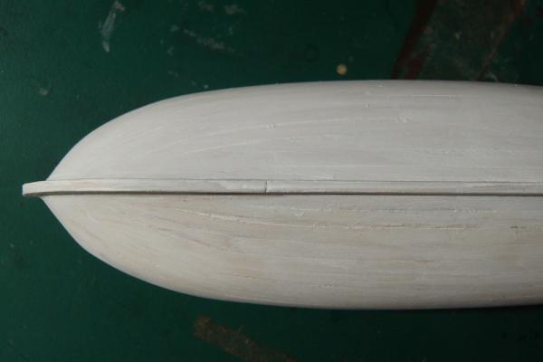
Toni, Are you sure? Both my garboard strakes end 3/16" beyond the forward end of the keel's scarph joint (I just remeasured them), which is as near to Chuck's layout as my eye can judge. The instructions say it should start "just forward of the scarph...don't start it too far forward". From other logs, I didn't think it should go much farther than that or the rest of the planks would be too squeezed as they ran in to the stem; the instructions give the same warning. I also tried to taper the garboard at least as much as I saw in other logs, I think it's more than Chuck's, to allow for a smoother run. Can you clarify what you're seeing in the photo that gives you concern? At this point I've done all but the last few planks. One thing I didn't do quite right is keep the ends of the next few planks symmetrical; if you view the boat head on, they don't meet up in the same place across the stem. I didn't notice this until I was past the point of being willing to rip them all out, but I adjusted the next few planks to compensate back to even, and the area where they don't match will be covered by paint. Looking back at my last photo, you may be seeing a combination of the 2nd planks not quite matching up, and camera angle foreshortening the port one. But I'd be happy to hear more, to understand if I'm missing something.
- 64 replies
-
- 3
-
-
- 18th century longboat
- model shipways
- (and 1 more)
-
I admire, and aspire to, your patience. Very nice.
-
Western river boats certainly weren't the King's navy. Great details, thanks for sharing.