
Robert29
-
Posts
416 -
Joined
-
Last visited
5 Followers


Recent Profile Visitors
4,028 profile views


-
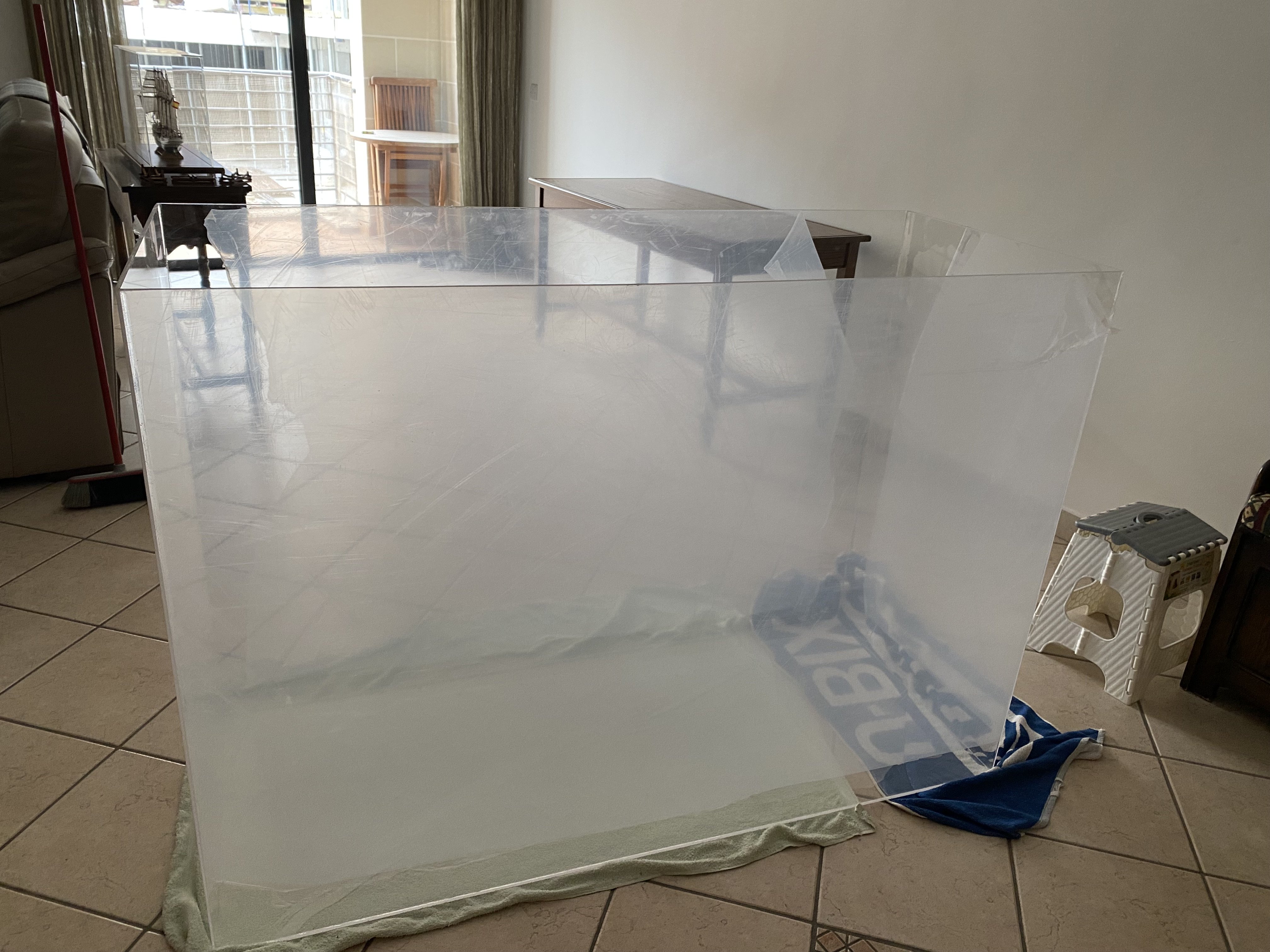
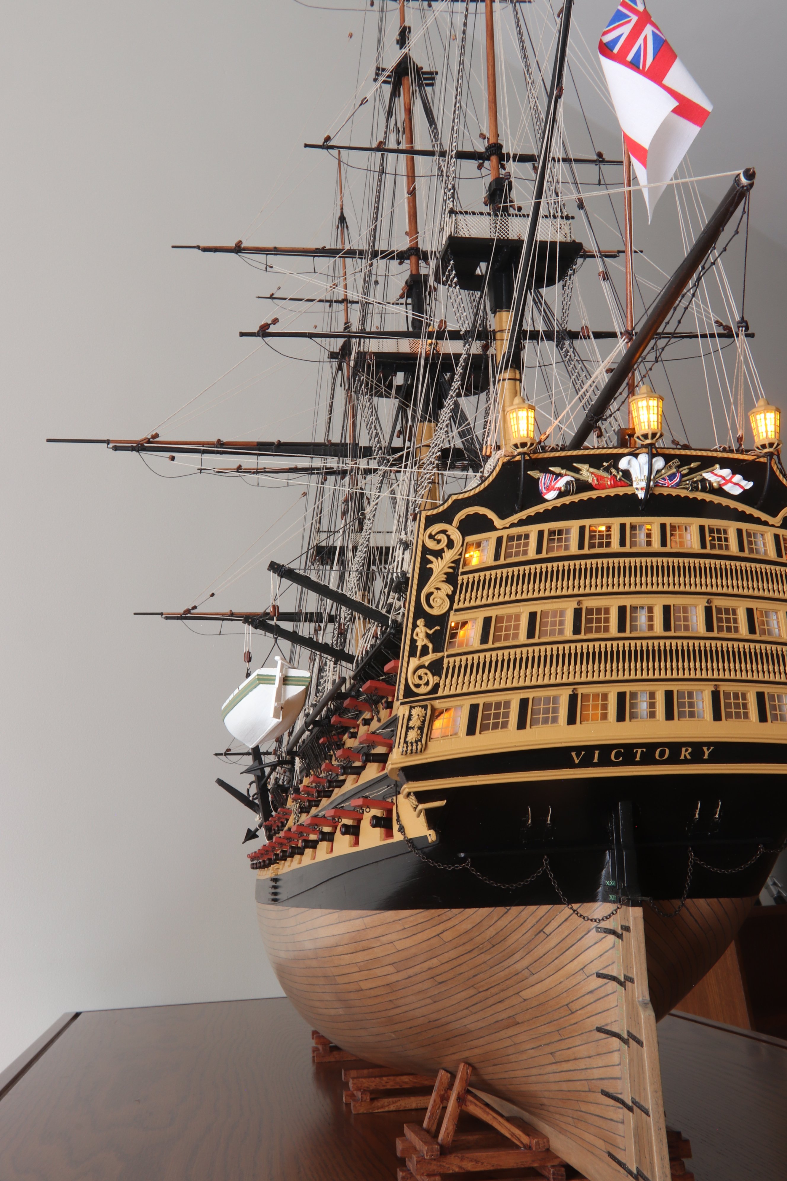
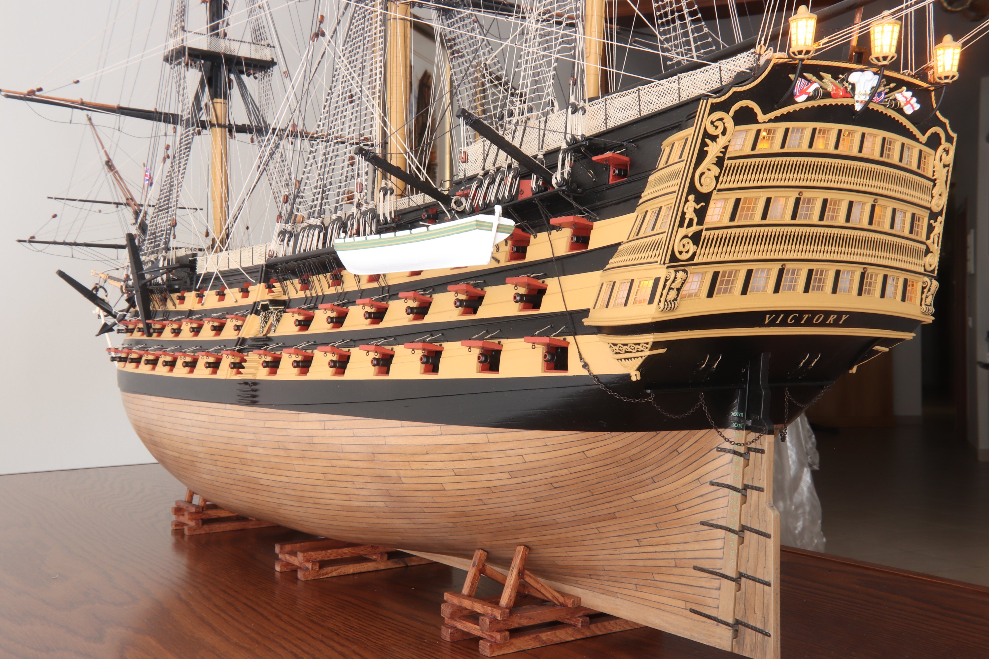
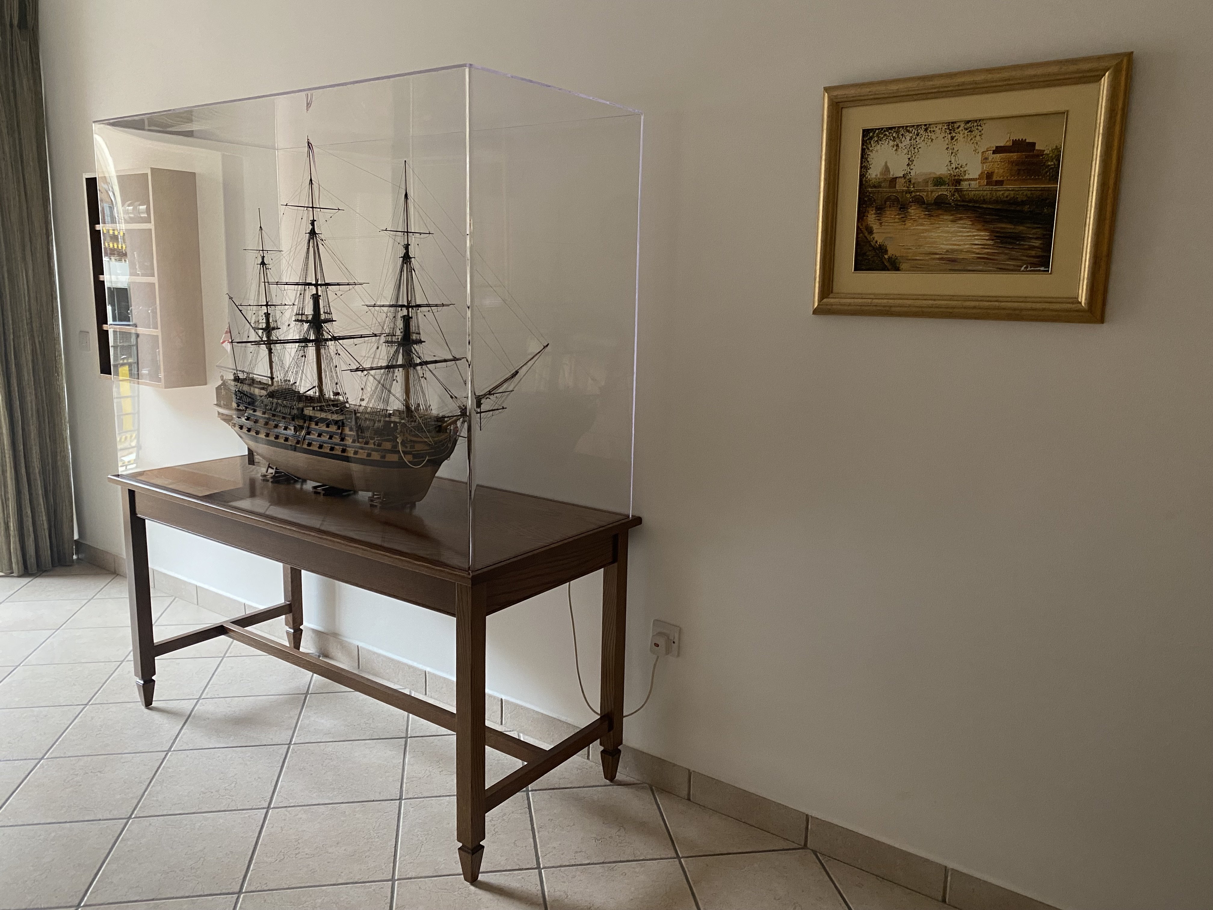
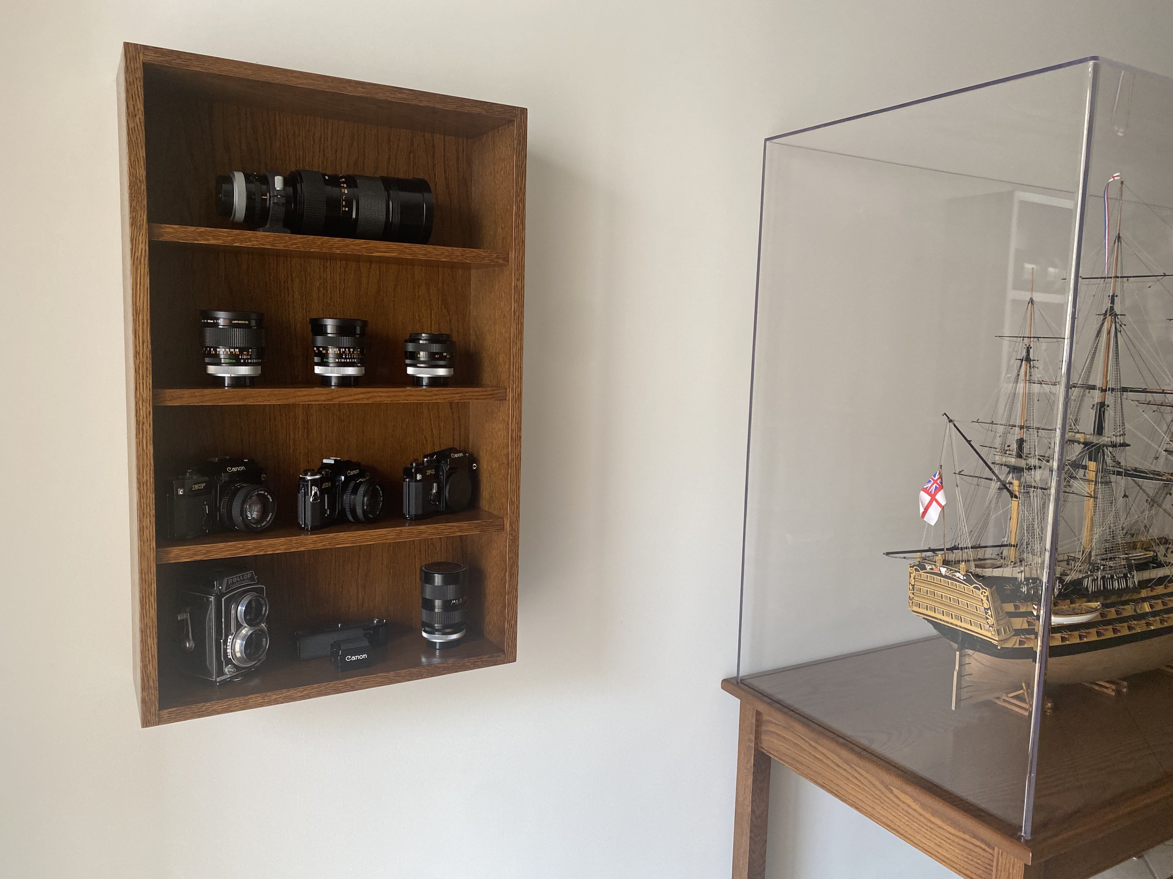
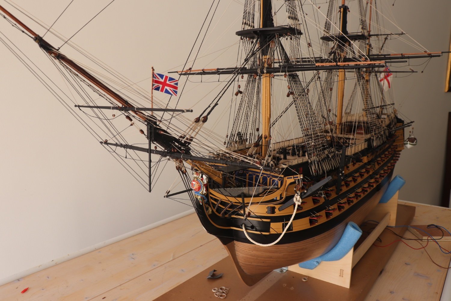
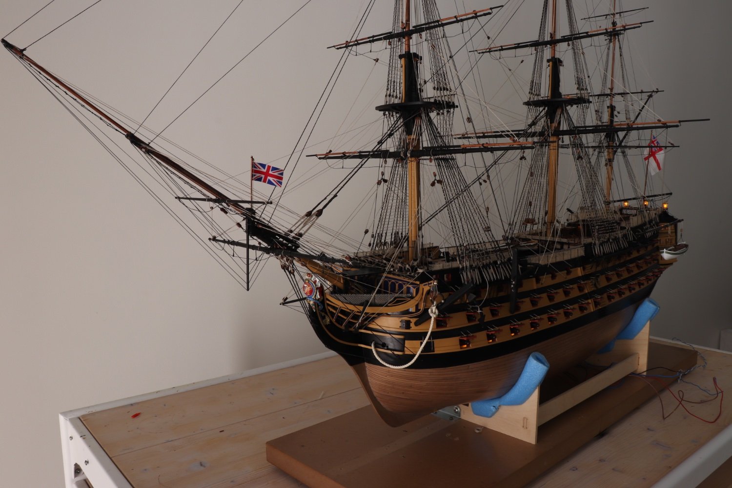
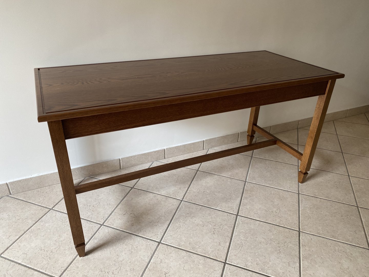
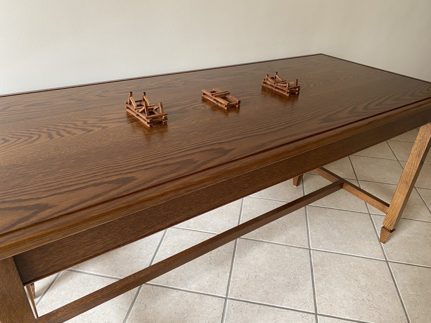
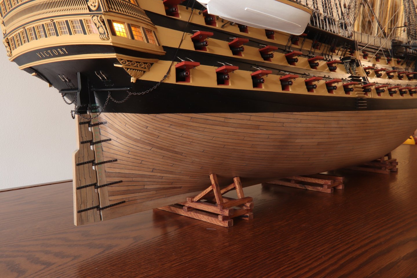
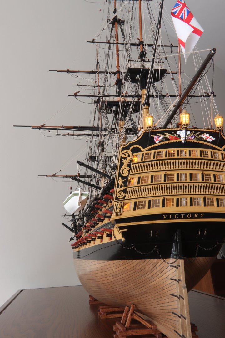
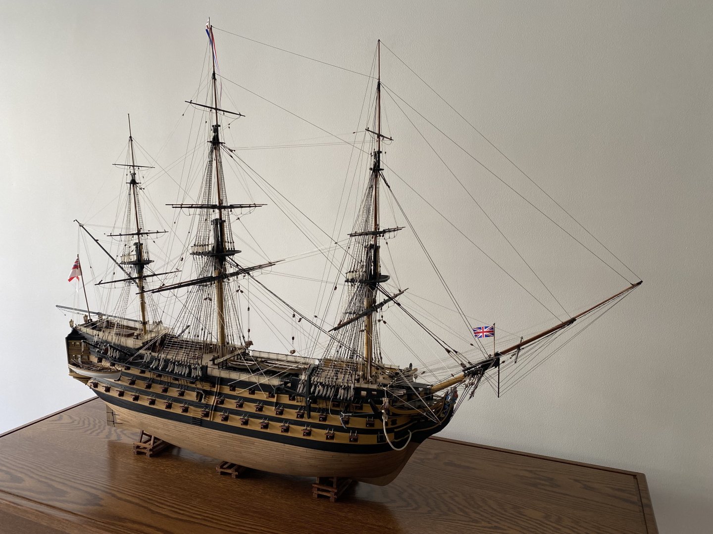
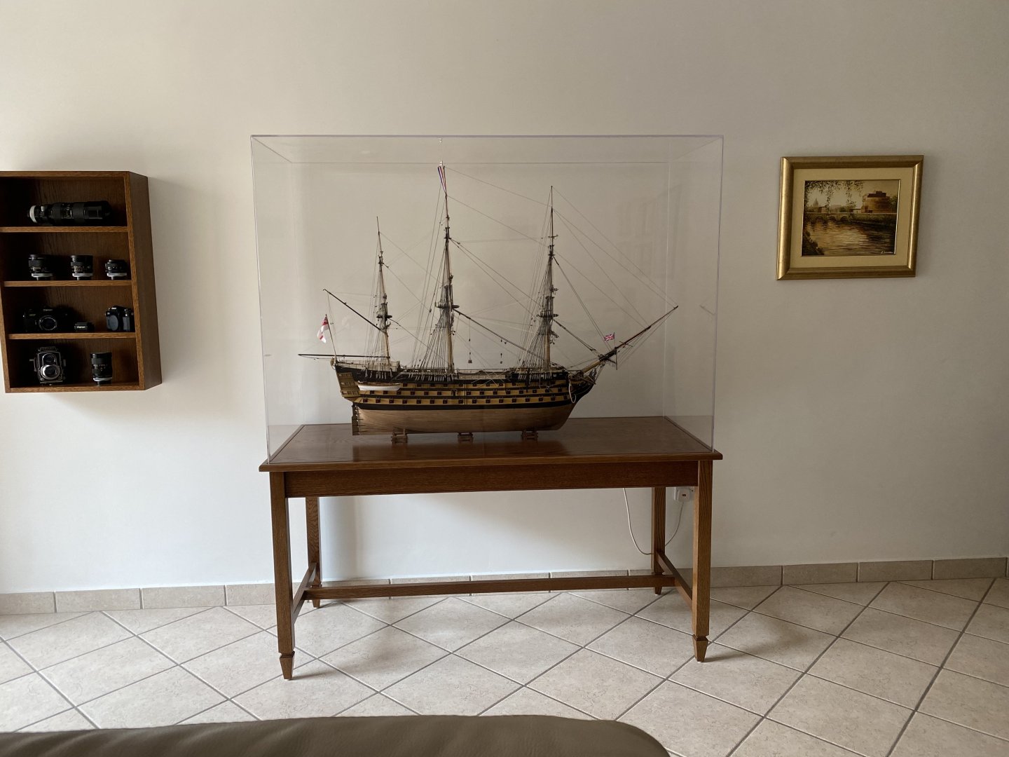
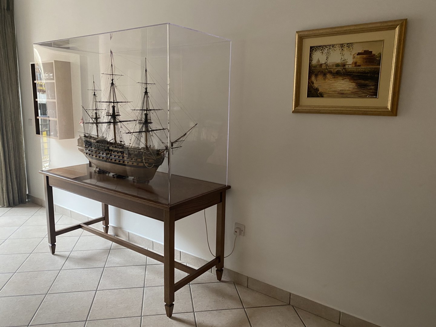
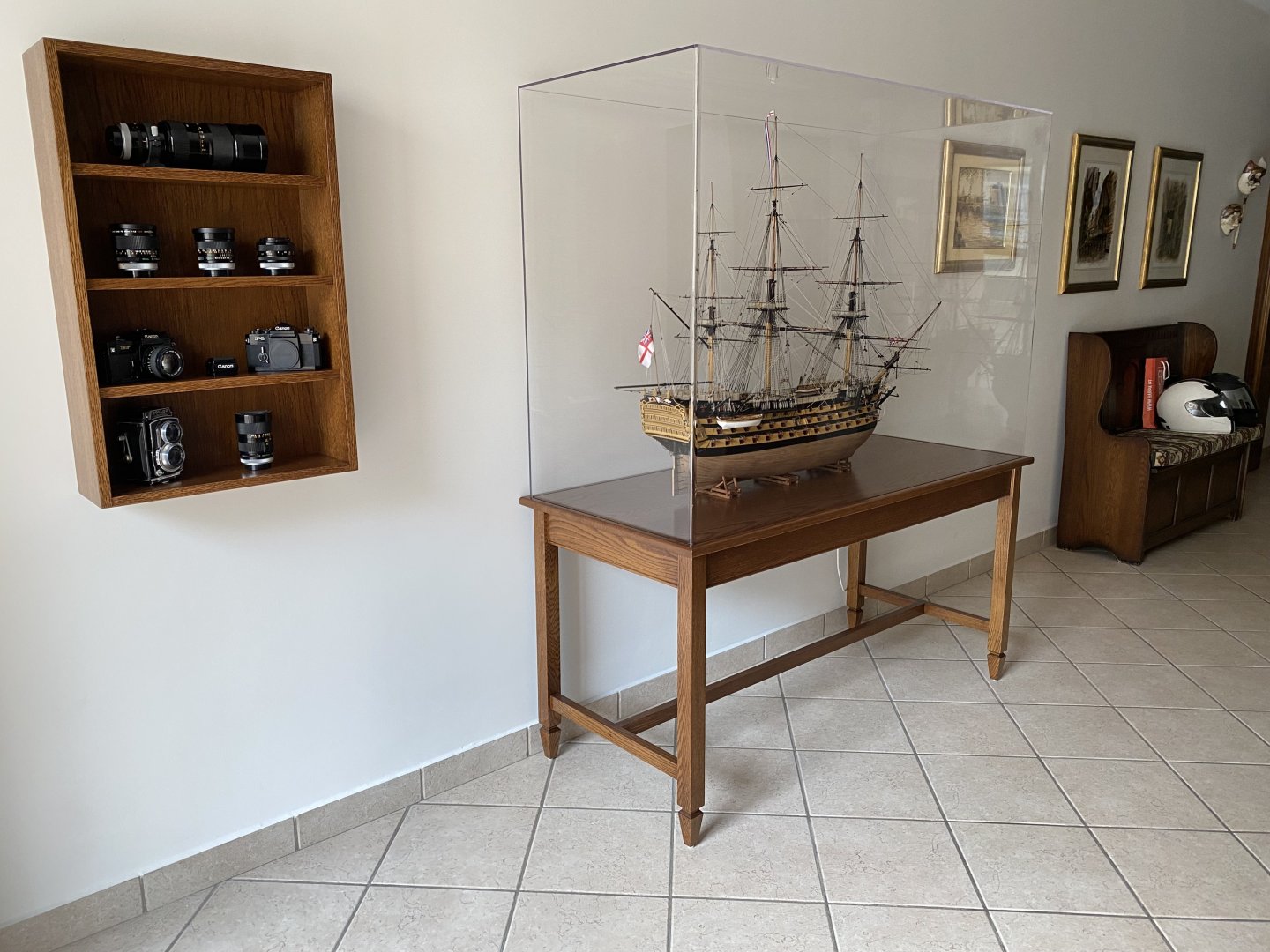
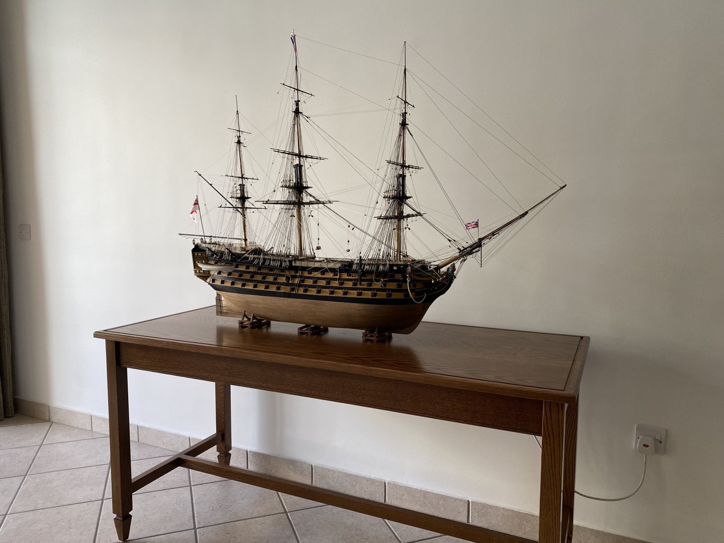
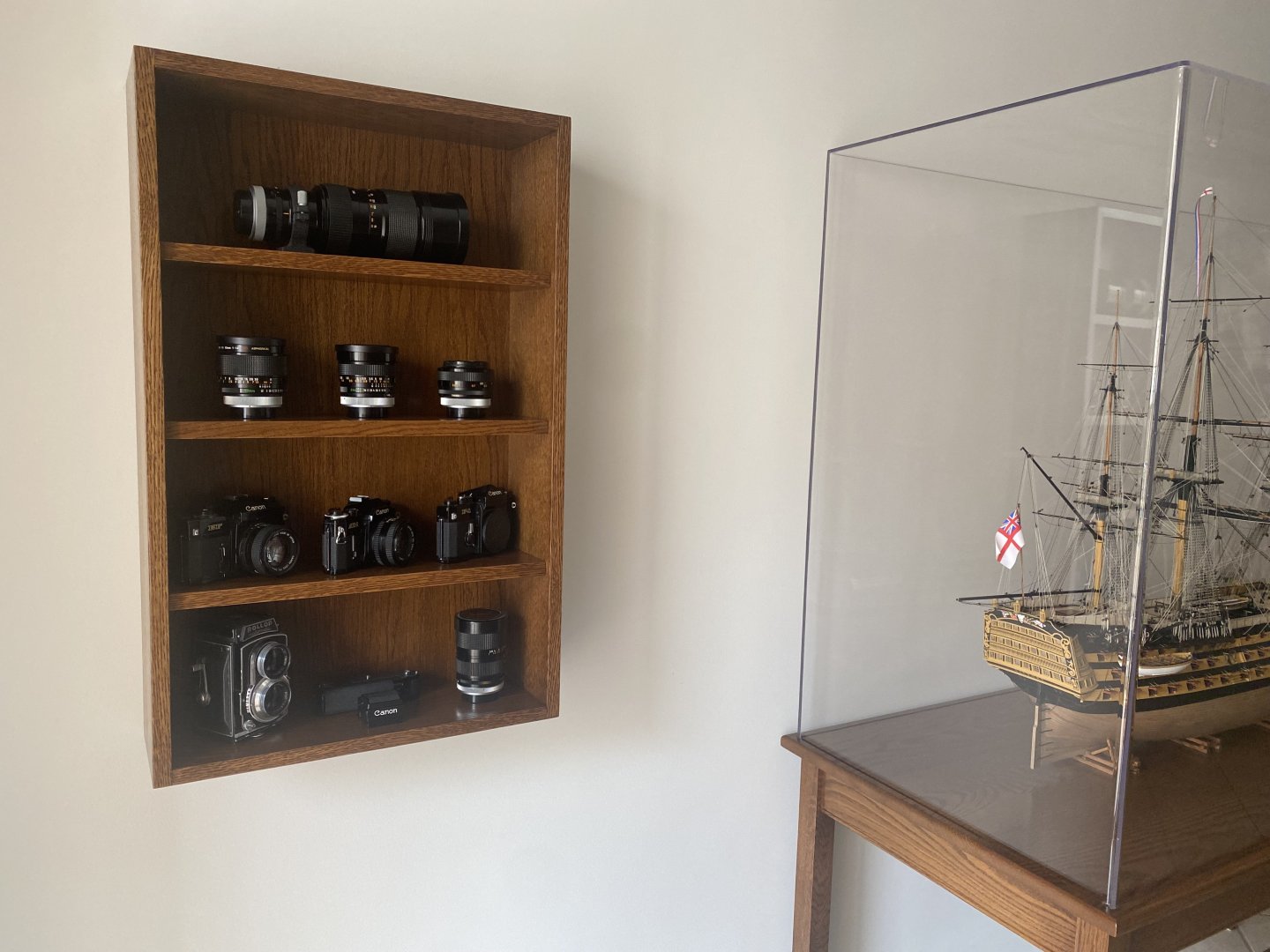
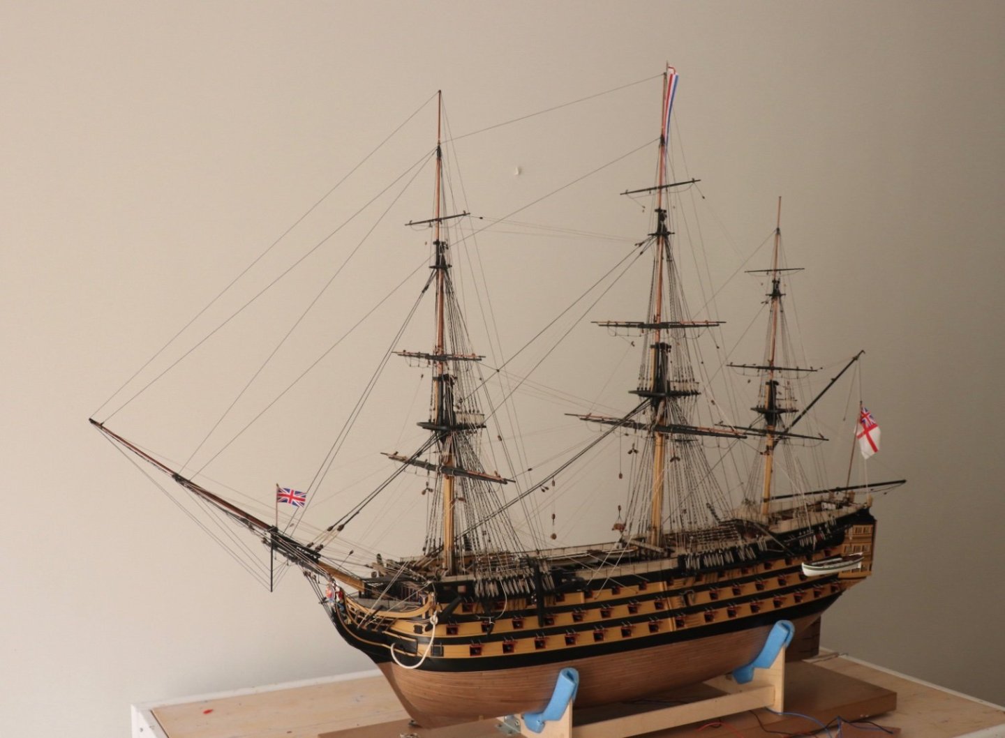
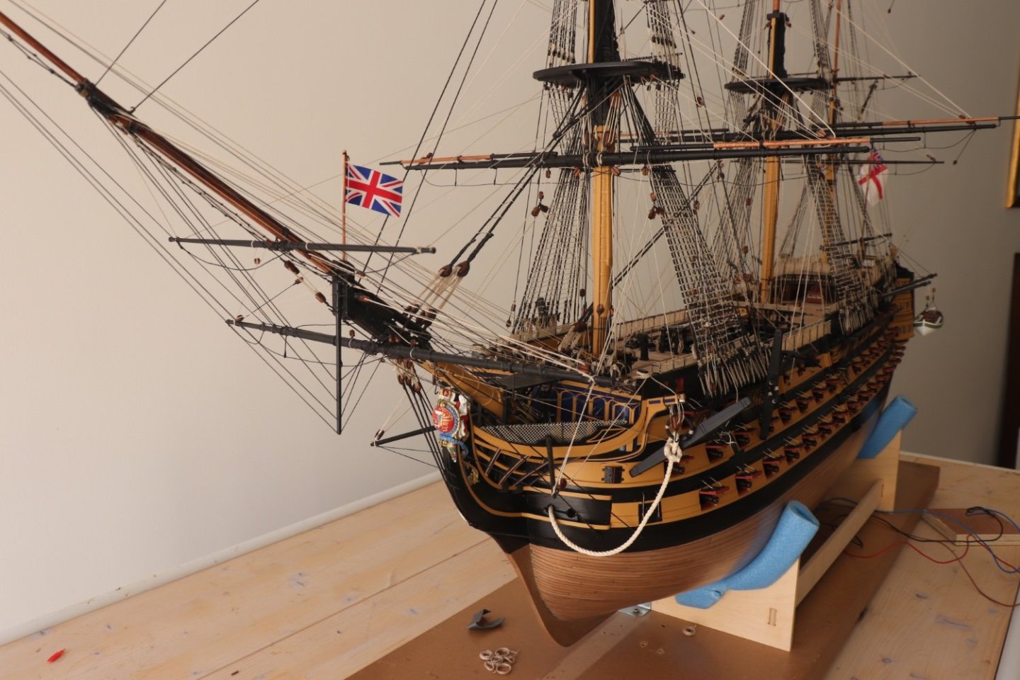
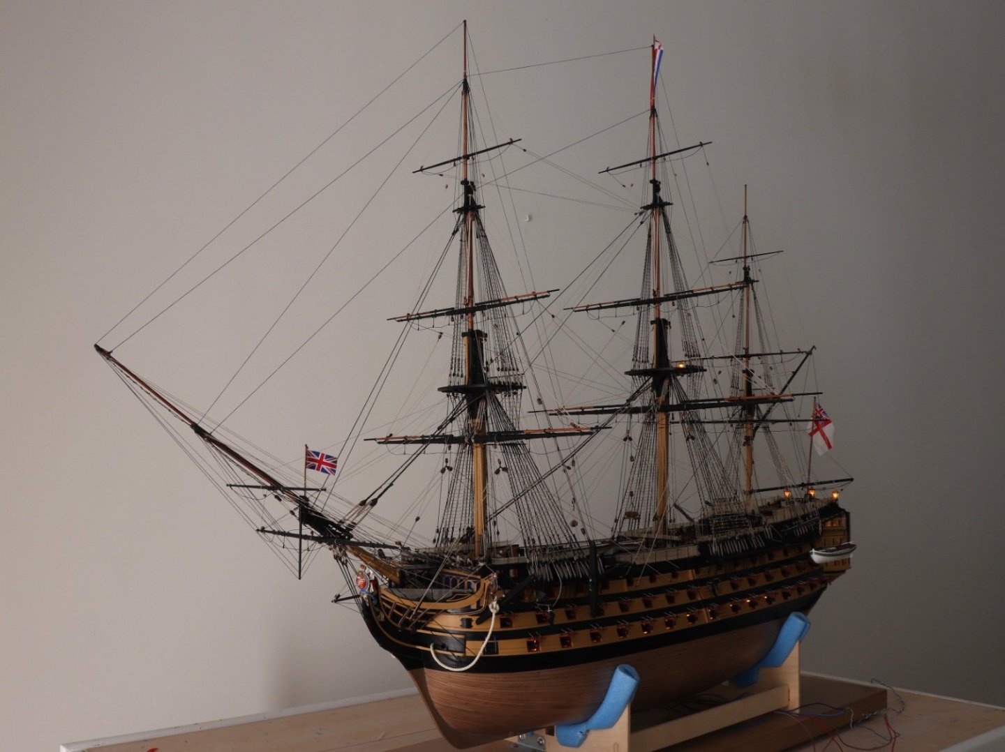
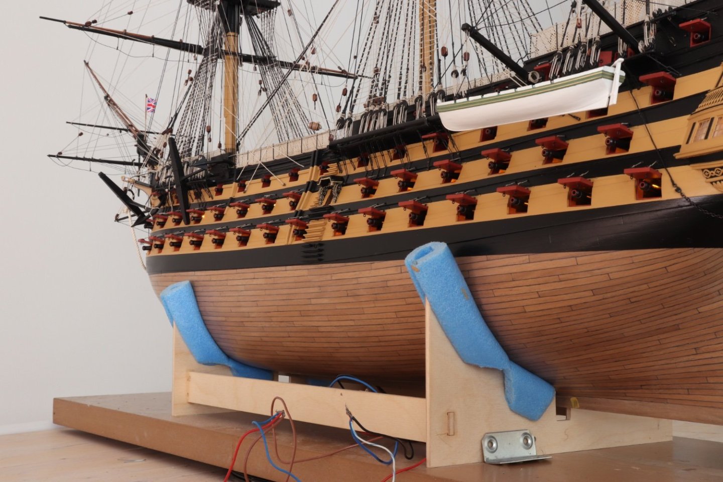
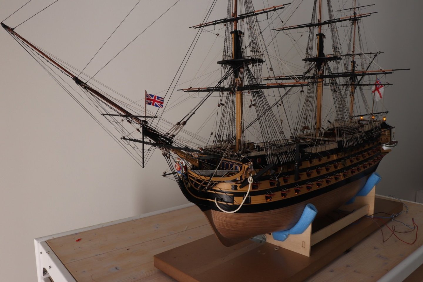
 Thank you Michael for your kind comments. Haven't visited my log for quite some time. Finally I received the case and the table. First I had ordered the acrylic case and had to wait to have it in hand before I ordered the table as I had to have the exact dimensions to cut the groove on the table surface to take the case. This took quite some time as its becoming quite difficult to find a carpenter to do something custom made. Acrylic case and table ready to take HMS Victory. Stands in place to take the ship with holes drilled through the table, The two end ones to take the threaded rods from the keel and bolted from under the table to keep it in place and the middle one to pass the wires from the keel to the power supply under the table. HMS Victory in place. And finally, after over 5 years working on her, covered and placed in a prominent place in my apartment where I hope she will stand for years to come and whenever I look at her reminds of the hours I spent building her. Now I am taking a break from ship building and my next project is reconditioning my small collection of Canon SLR Cameras and Lenses, plus a 'Rollop" twin lens camera which belonged to my late father, thus this camera has a big sentimental value for me. They are the film type and since the electronic DSLR came out I haven't used them for years and now in need of a very deep cleaning job and also some repairs for which I ordered some tools and will do the job myself. I want to bring them back to full working condition and maybe try taking a few photos with them as well. When I ordered the table for the Victory I also ordered a small display cabinet for them. I thank once again all those who followed my build log and found so much encouragement from. I hope my build log will be of help to others, as honestly I found so much help and ideas from other builders on this site. Regards Robert

- 527 replies
-
- 16
-

-

-

-
- caldercraft
- victory
- (and 1 more)
-
Hi Graham, as always you come up with brilliant ideas how to tackle certain jobs. Those decorative scrolls are beautiful. I had also made some changes to the scrolls on my model, but your idea is impressive. Keep up you good work. Robert
-
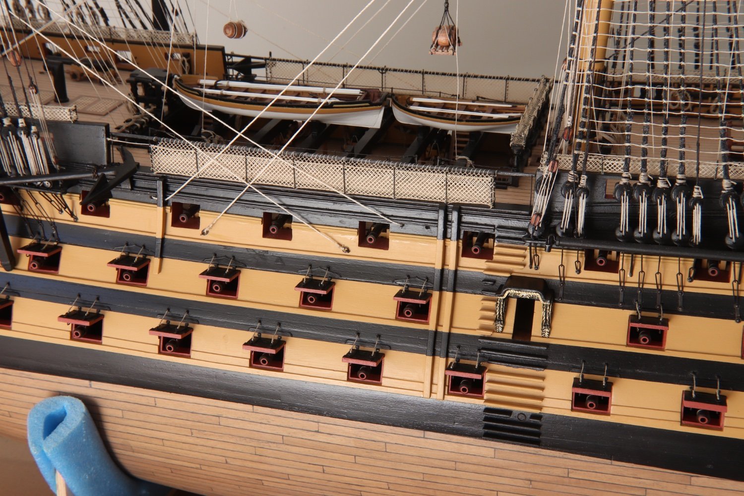
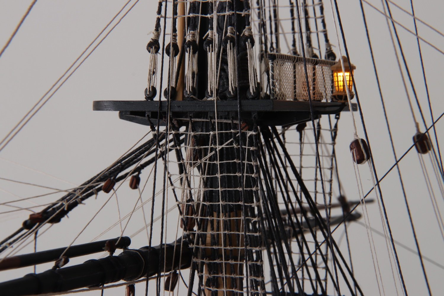
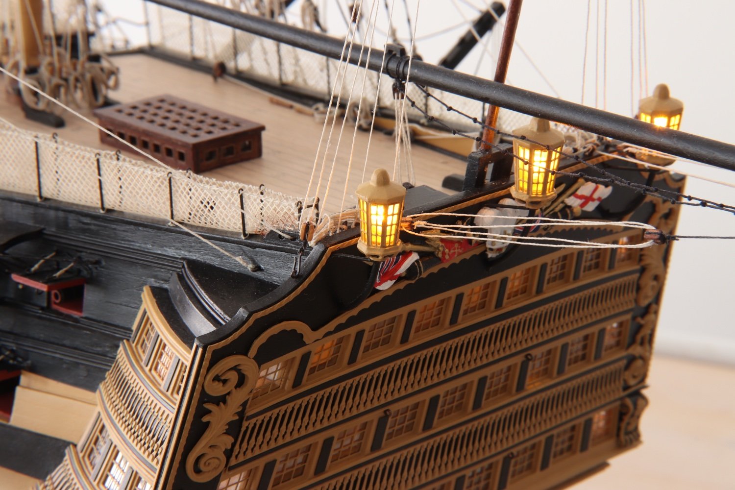
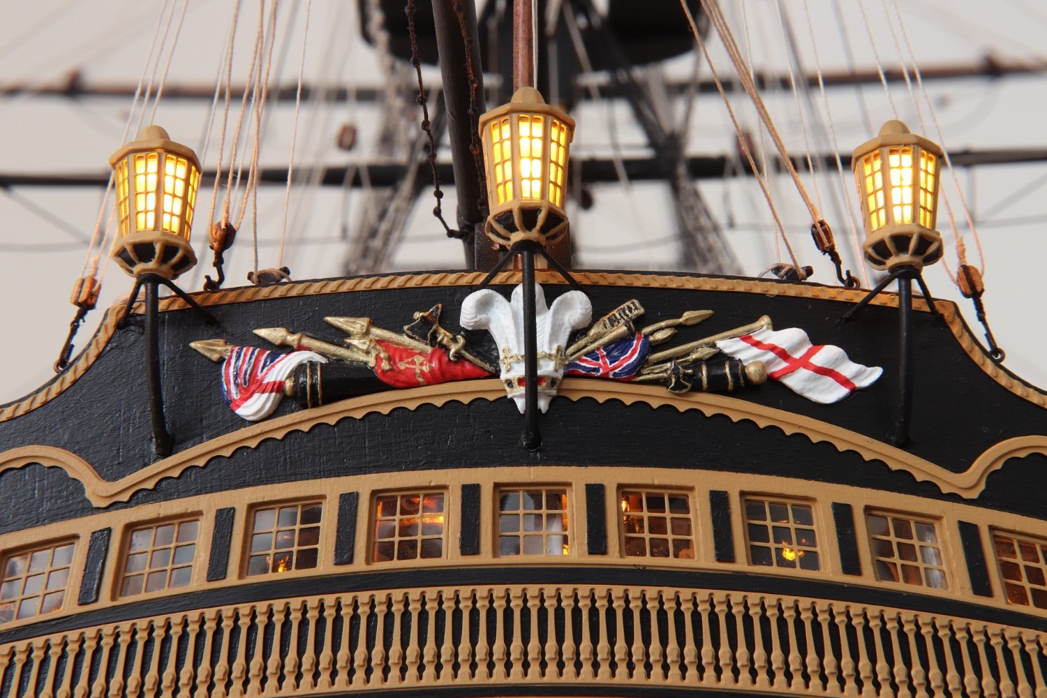
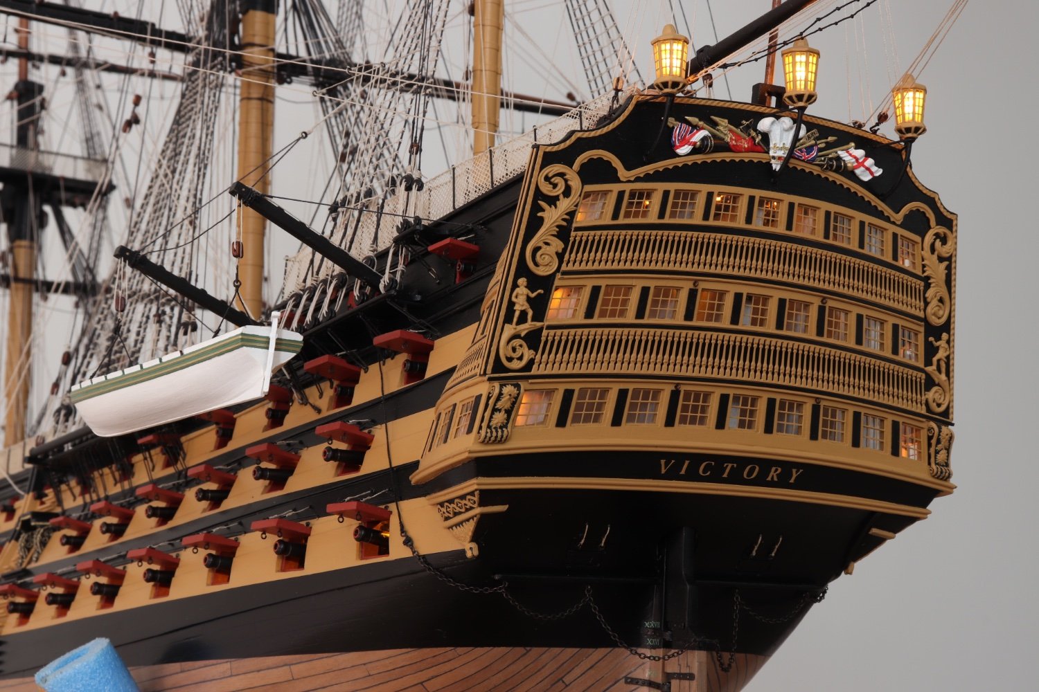
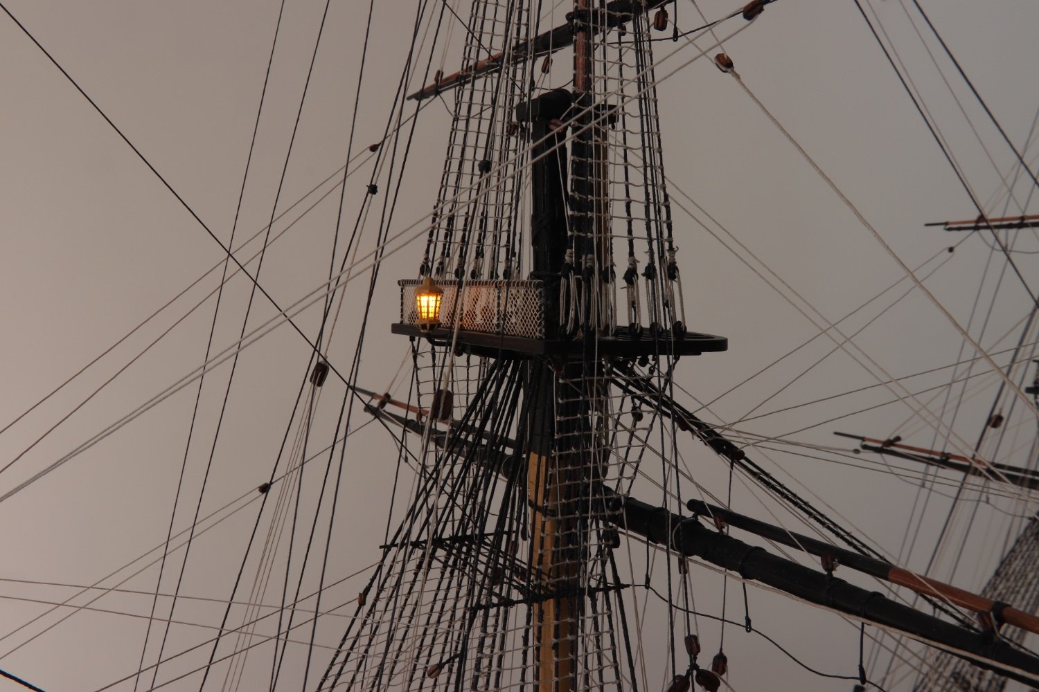
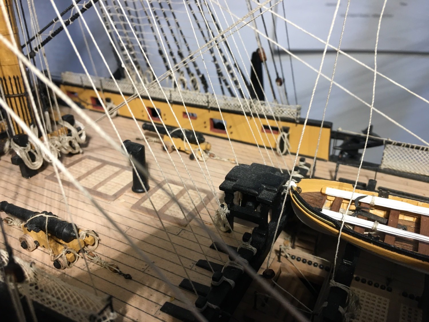
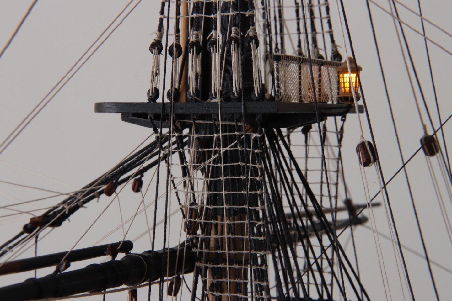
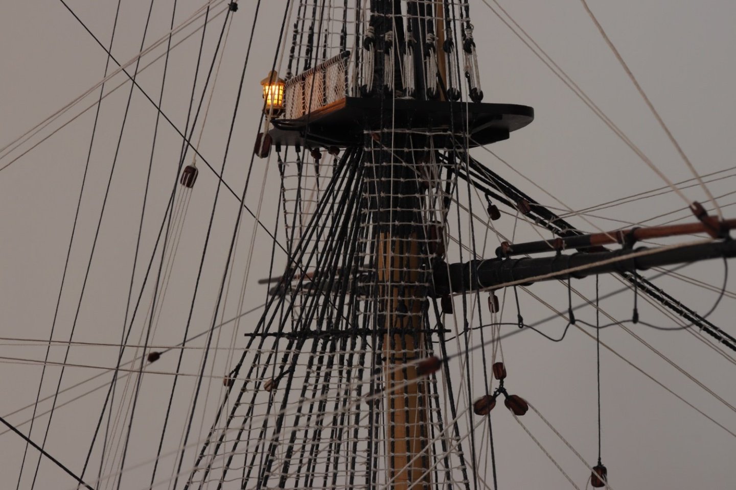
Thank you all for the comments. Bruce, As for the lighting, electronic wise I tried to keep it as simple as possible. Anything that goes wrong you cannot repair inside the model. The system only involves led's, a resistor for each led and wired them in parallel so I can put as much led's as I want to, just calculate the total amperage of the led's, and make sure the power supply (transformer, its practically impossible to run all those led's on batteries) has the adequate amperage. The other advantage of having them in parallel is that if any led or resistor is burnt, which is very unlikely, will not effect the others. Where possible I also wired them in a ring circuit so that if I have a wire becoming disconnected they will still have the voltage supply on them. My main concern was that I did not want to let any wiring showing, not even the once going out to the power supply. A thing I wish I would have done is have added just a few hanging lanterns on the quarterdeck and the bow so when lit in the dark more details could be seen. This would have been more difficult to hide the wiring. All in all I am quite satisfied with the result, but obviously there are always some things you would do differently if you had to do them agin. Robert
- 527 replies
-
- 4
-
-
- caldercraft
- victory
- (and 1 more)
-
Very nicely done Graham. Robert
-
Andrew, Chris, Graham, Sjors, Ian, Julian, Mort, Malcolm, B.E., Anthony, Mugje, thank you all for your coments. Also thank you for all the likes. Robert
- 527 replies
-
- 1
-
-
- caldercraft
- victory
- (and 1 more)
-
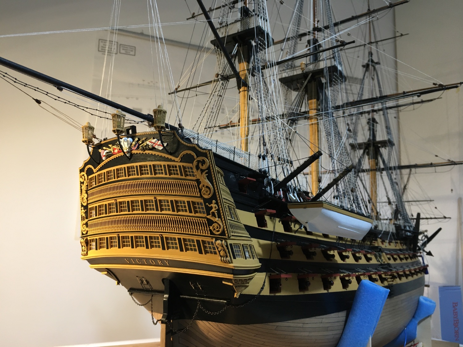
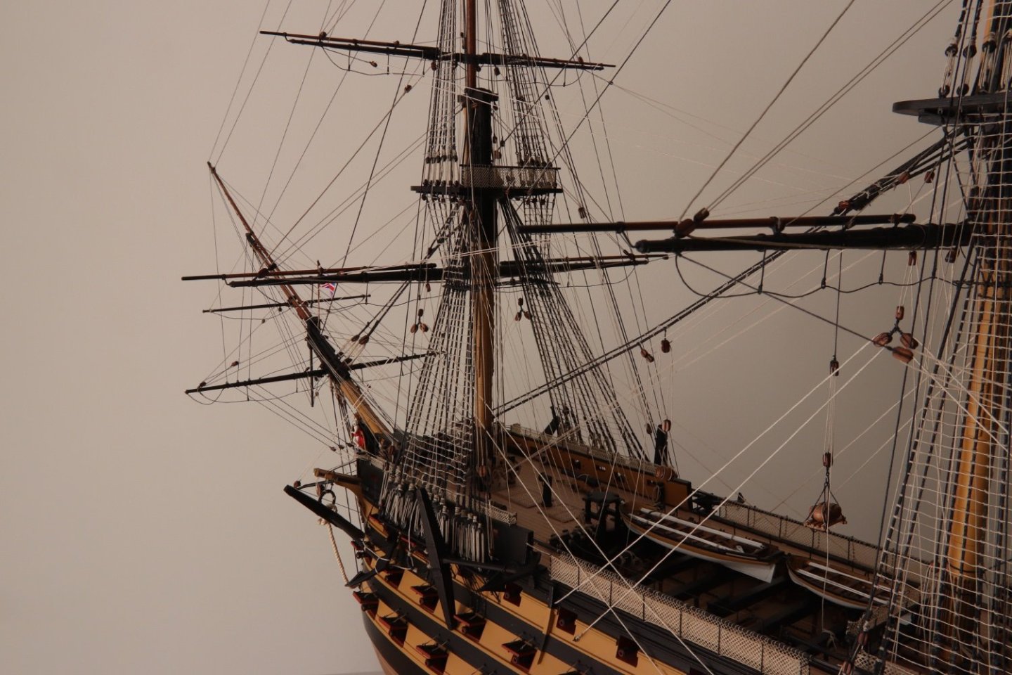
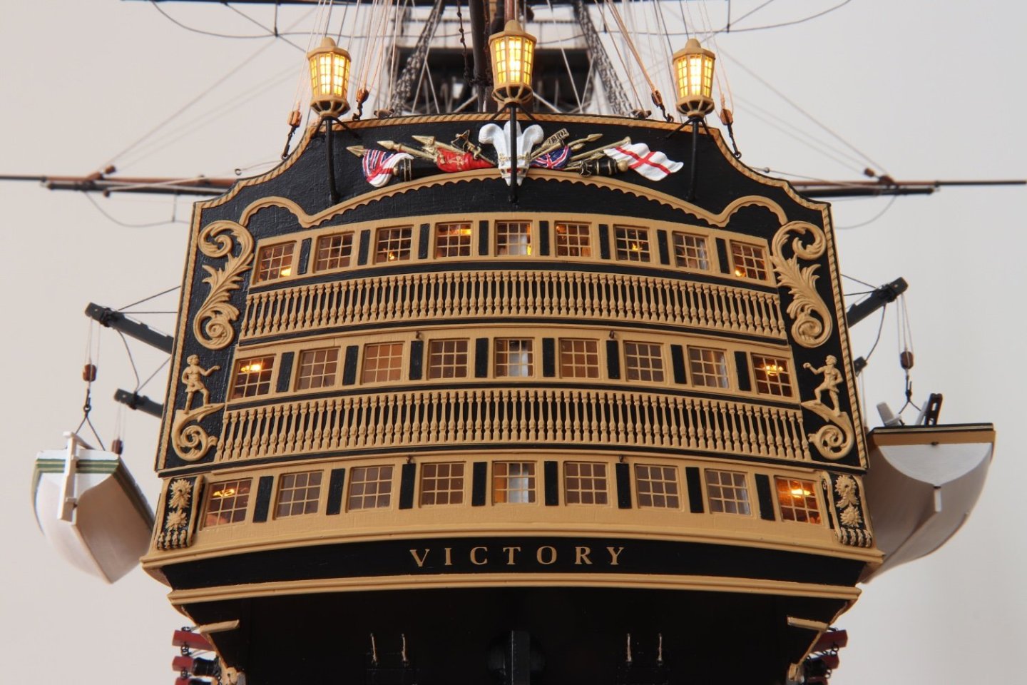
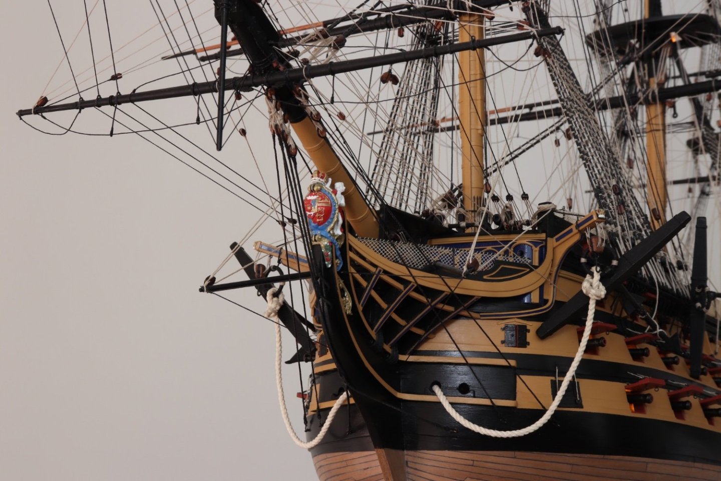
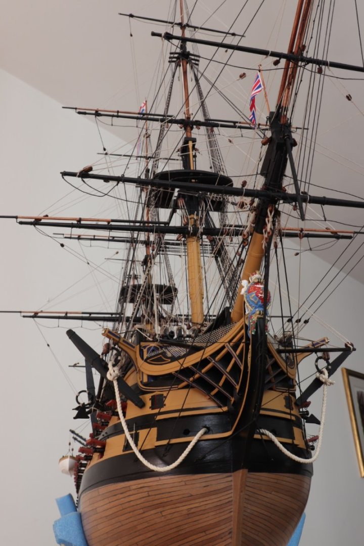
Finally HMS Victory long voyage comes to an end. I have posted a few photos but first of all I would like to thank all those who in any way contributed to my build, those who posted directly into my log, those who's logs I visited and took countless ideas, my log's followers and those who contributed with their encouraging comments and likes. I hope that my build would be of help to other builders, like so many others have been to me. Now I have to order an acrylic case to cover it and a table. I will post an image of it when I have it ready. Images with the lights on. Robert


- 527 replies
-
- 22
-
-
-
- caldercraft
- victory
- (and 1 more)
-
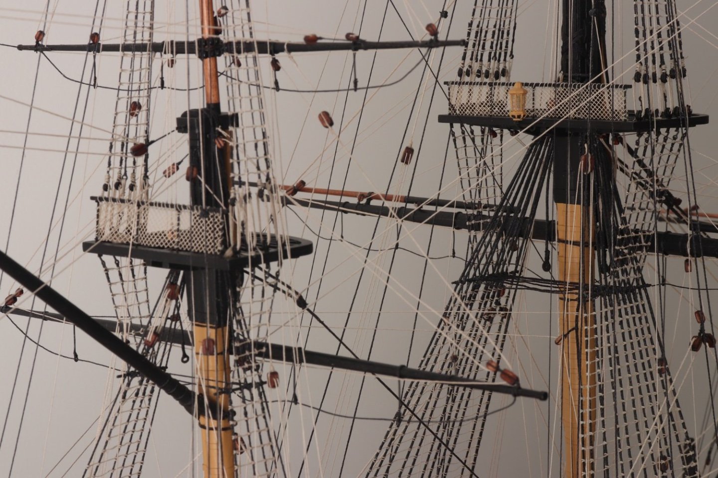
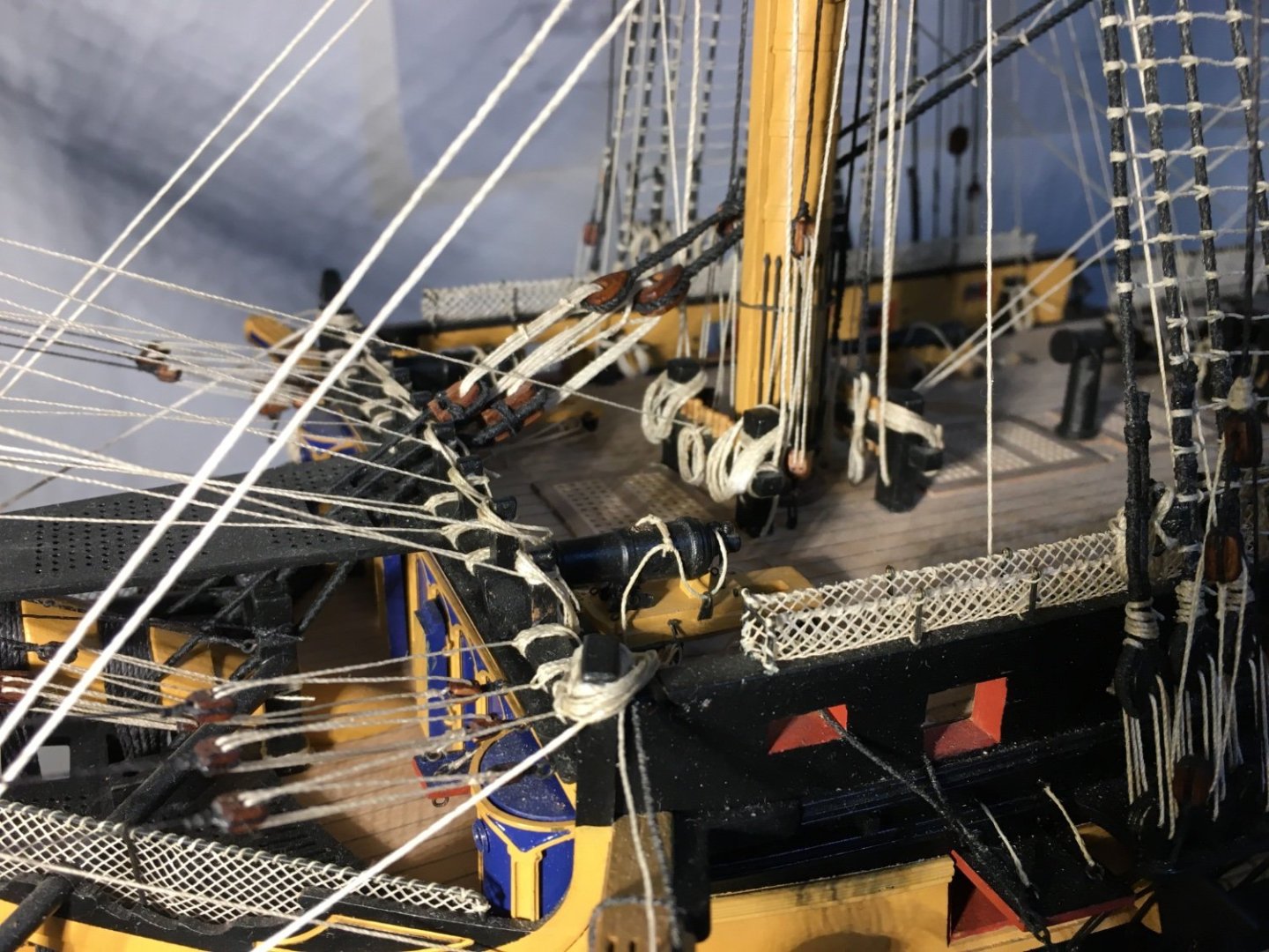
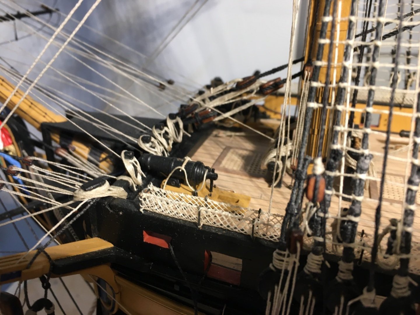
Some more detail to the Main Stay tackle Pendants. Robert The main stay fore tackle need some more tensioning. Robert

- 527 replies
-
- 10
-
-
-
- caldercraft
- victory
- (and 1 more)
-
Looking good Ron. Yes 0.5mm is quite thin and especially where the planks get narrower they break quite easily. Wetting and heating helps to minimise the problem. Robert
-
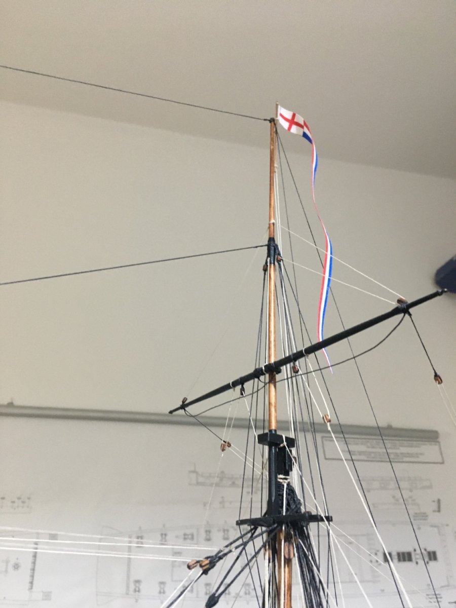
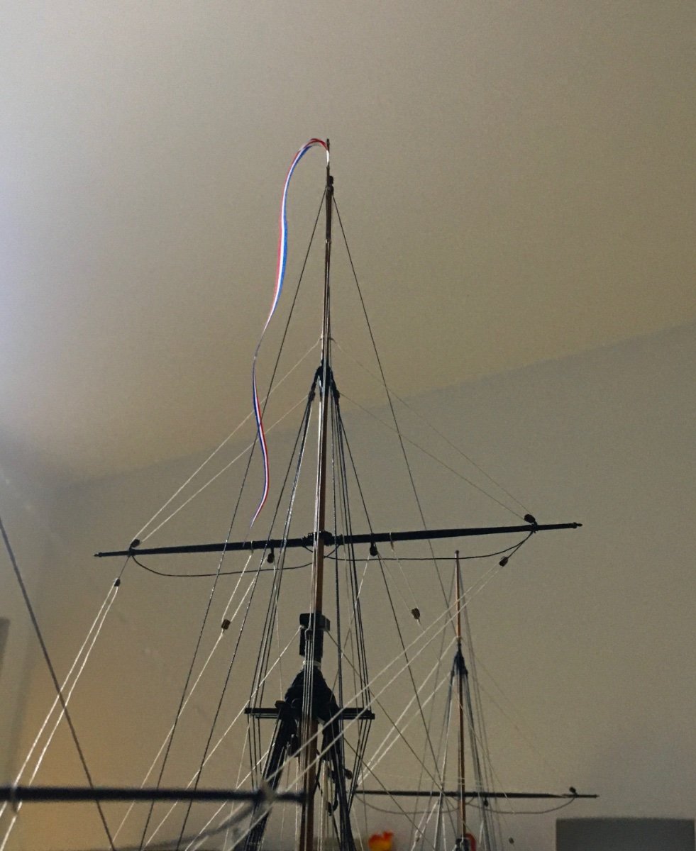
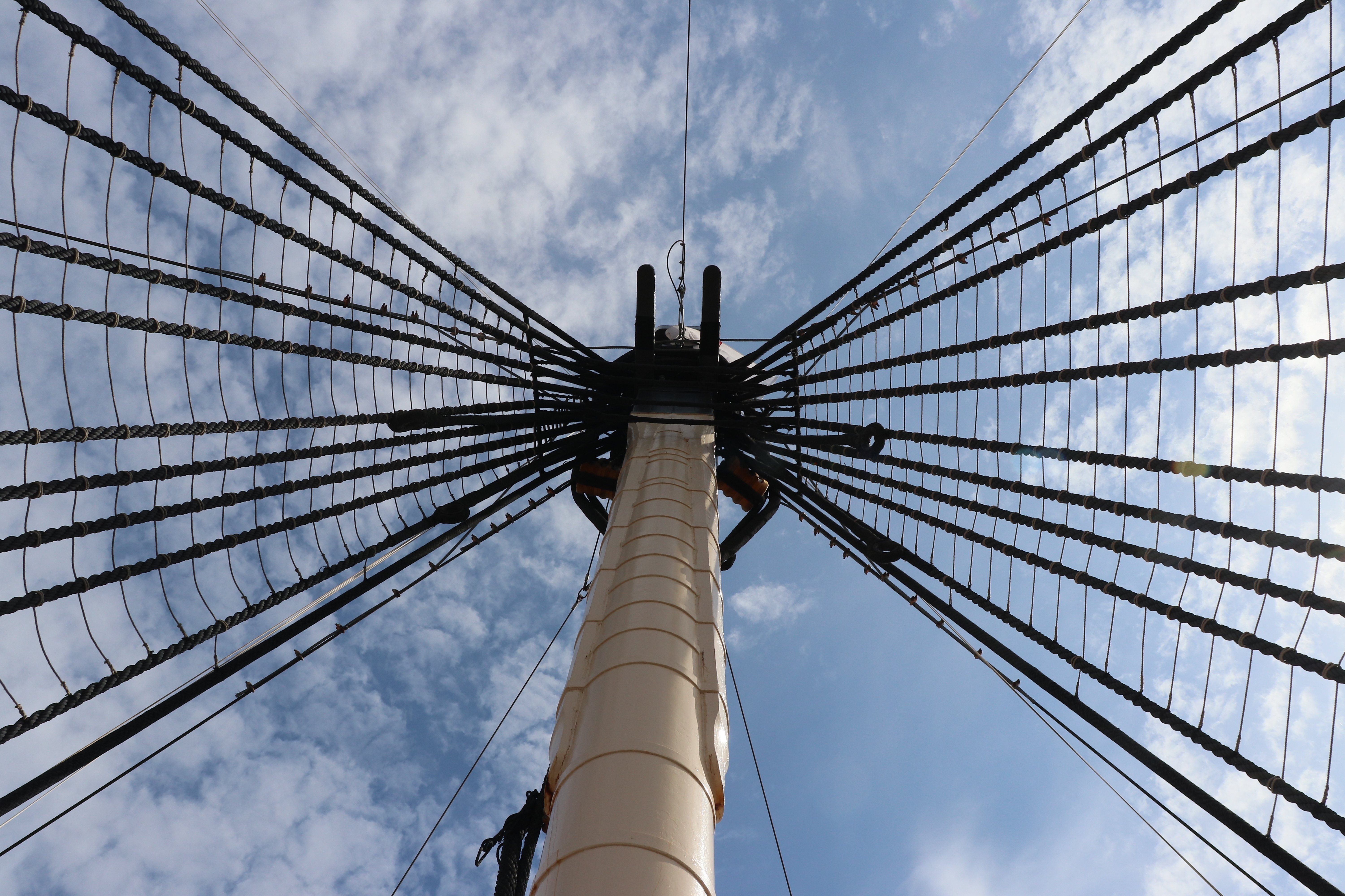
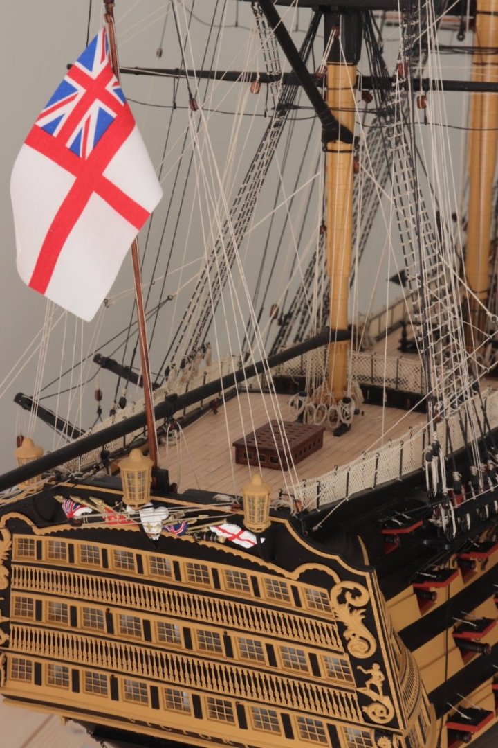
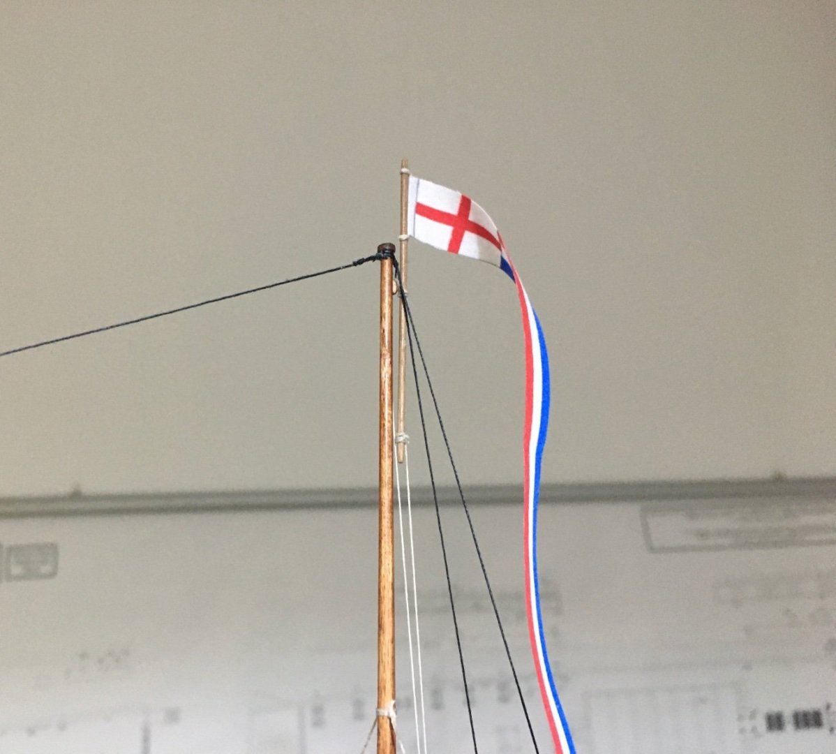
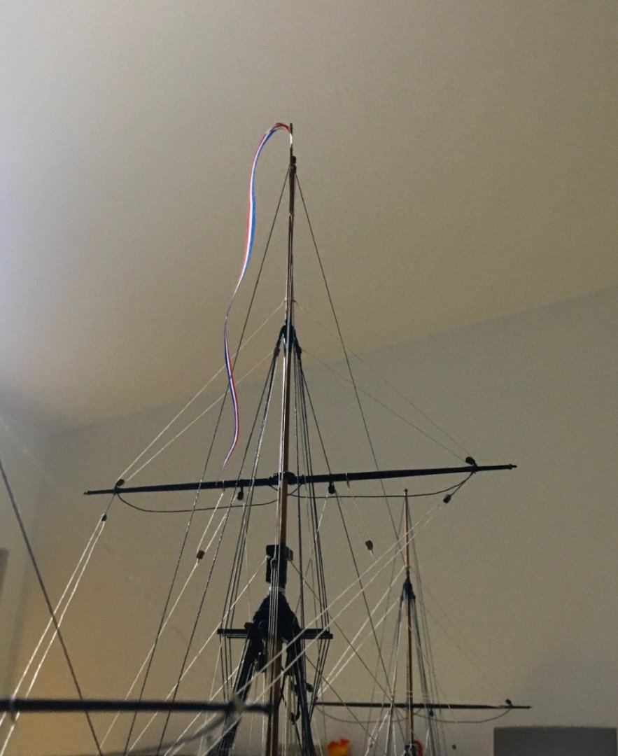
Thank you Ron, glad my build log is of some help to others like other build logs have been of great help to me. Case in point flying the pennant flag. I was wondering how to fit the pennant on the main mast and couldn't really find any details on the internet. Then I remembered seeing something on Gil Middleton's great build log. Gil had details how pig sticks were used and I used the same idea. The pig stick is hoisted above the mast head so that the flag is not fouled by the stays. The hoisting halyards are secured to the top. Also secured the kedge anchor on the starboard mizzen channel. Some more finishing touches to go. Robert

- 527 replies
-
- 12
-
-
- caldercraft
- victory
- (and 1 more)
-
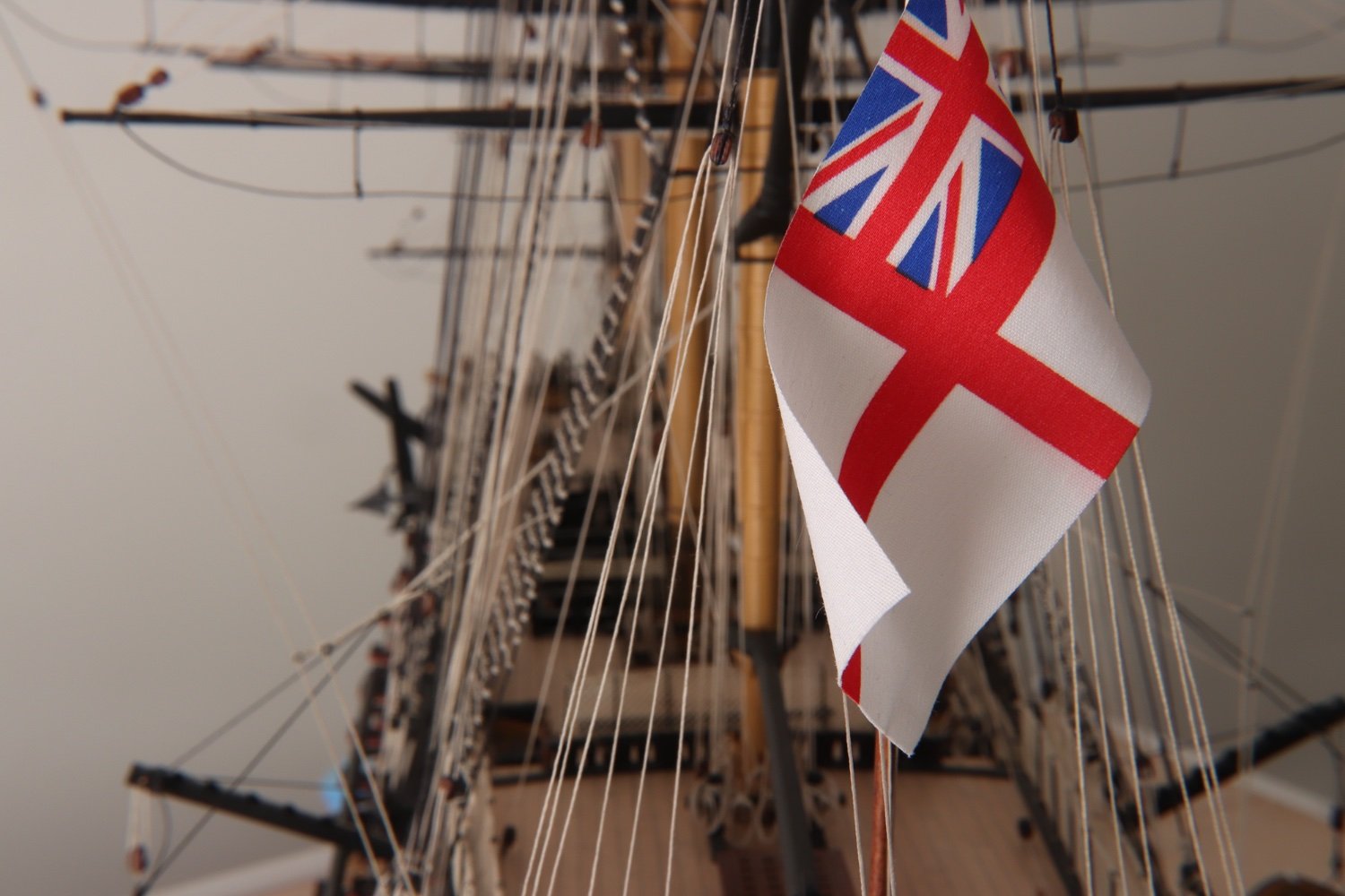
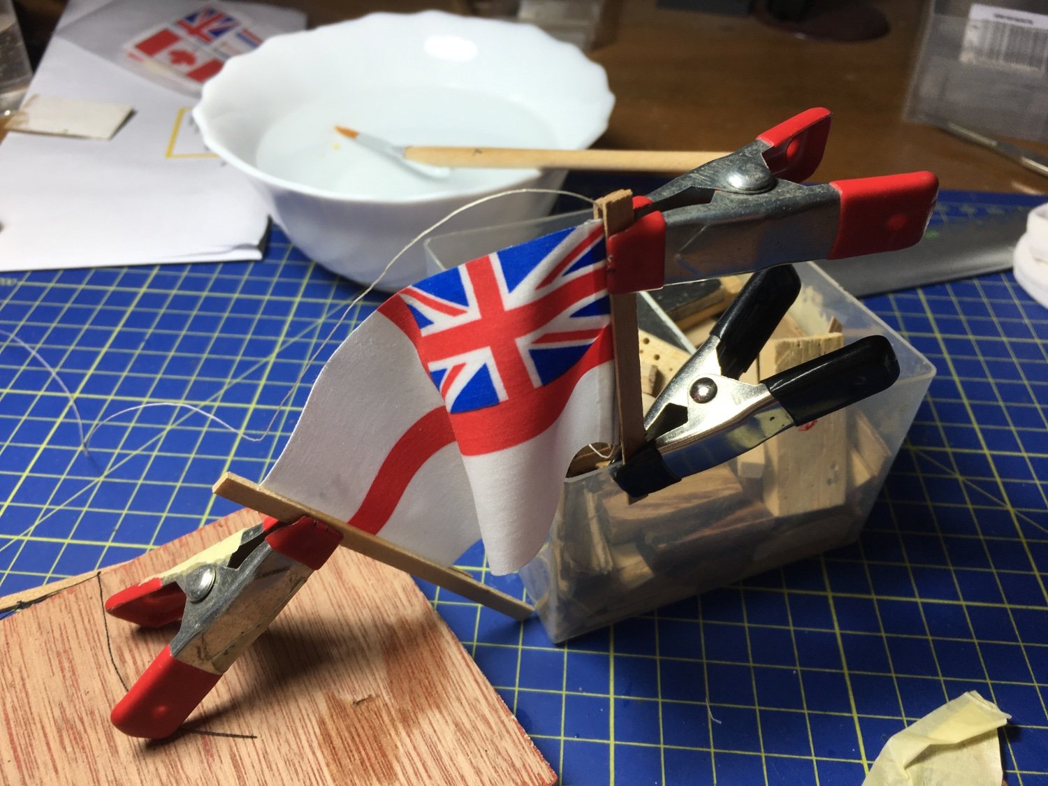
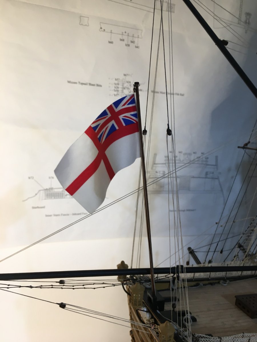
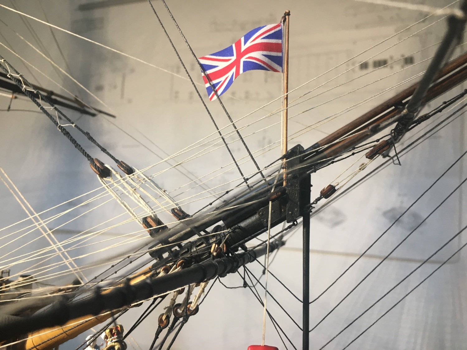
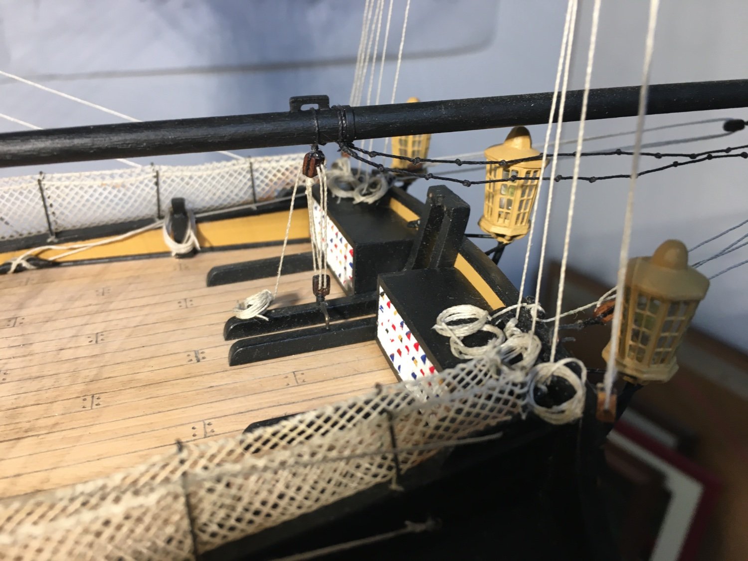
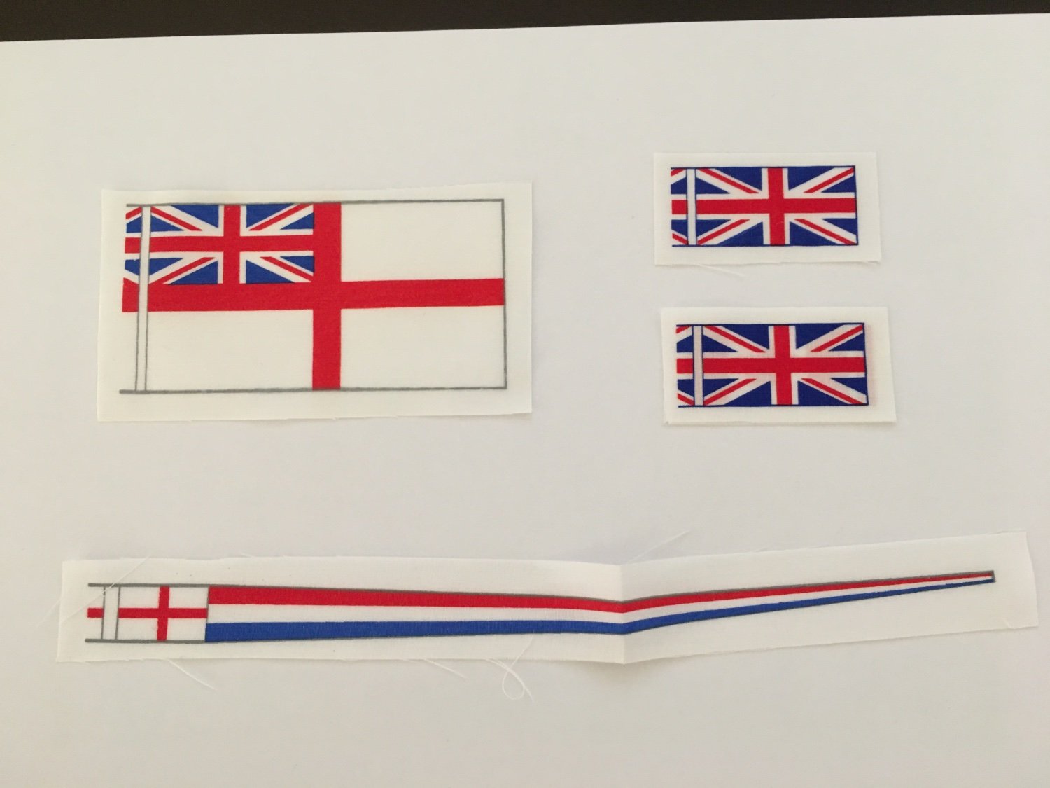
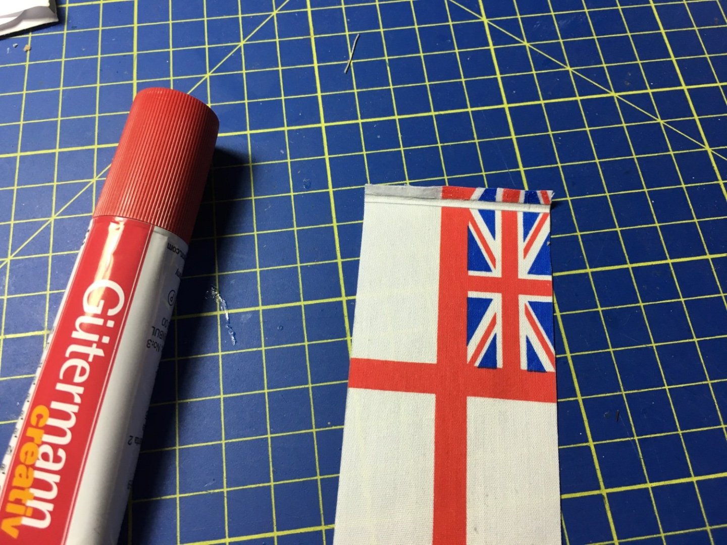
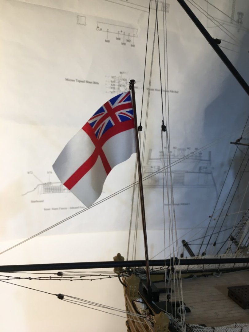
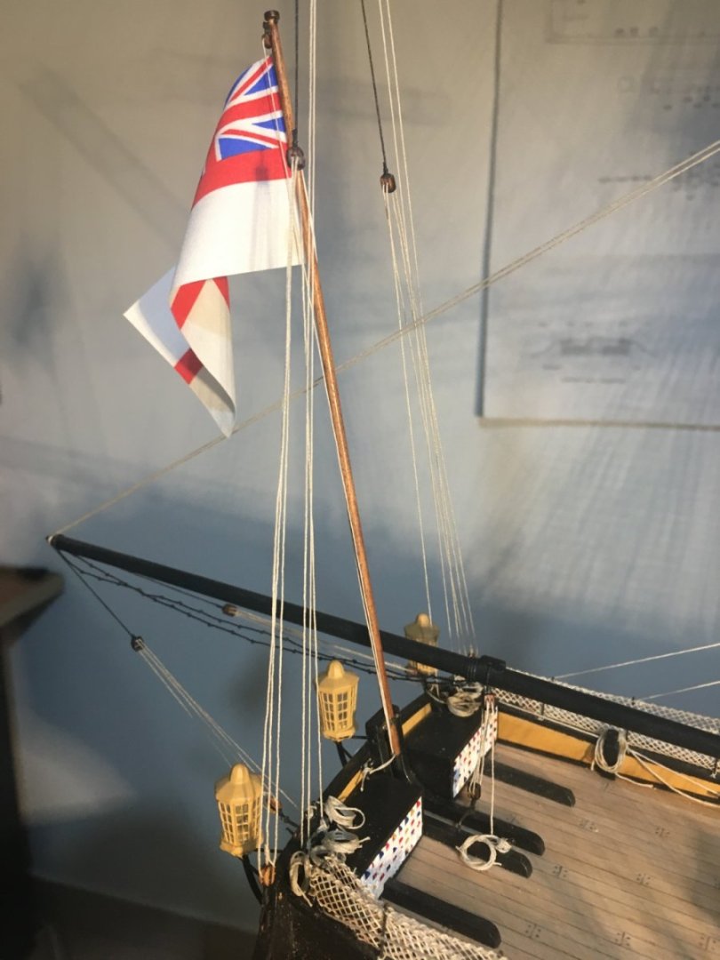
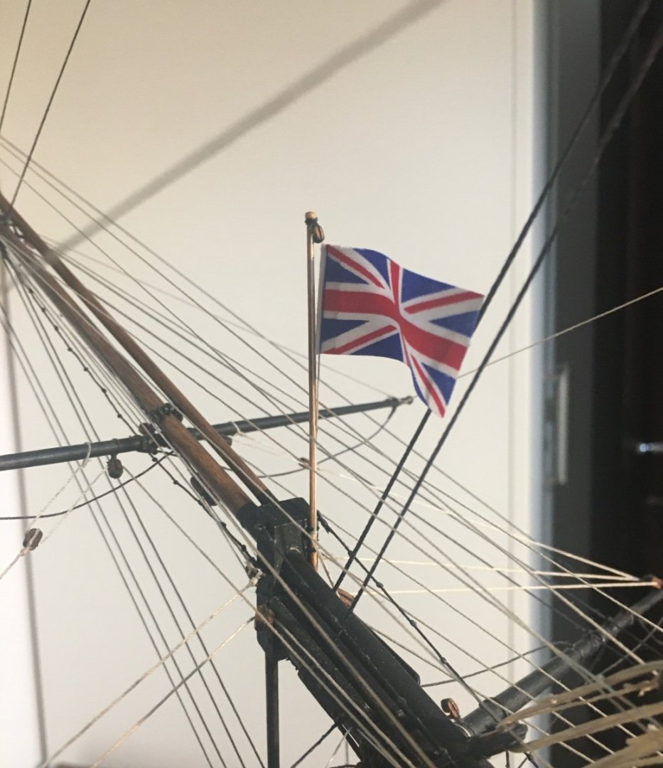
Thank you Ian and Graham. Getting closer to the finish. Fitted two flags and tried to make them look as realistic as possible. I used glue purposely for fabric. The brand is Guttermann, had used it on sails for another model, very good stuff. Didn't want to risk other glue, so for that very little bit I had to buy a new one, as the previous one I had, had dried up. Put glue on one side, placed the thread and attached the two faces. With a couple of clips I arranged the flag to look like it is sort of flying, then. with a brush I wetted it all with water and let it dry again. When I removed the clips it kept the shape. The ensign staff fitted in place and the ensign hoisted in place. The Union Jack also hoisted in place on the Jackstaff. Still have to fit the pennant. But first I have to check exactly where it goes and how it is fitted. Robert


- 527 replies
-
- 13
-
-
-
- caldercraft
- victory
- (and 1 more)
-
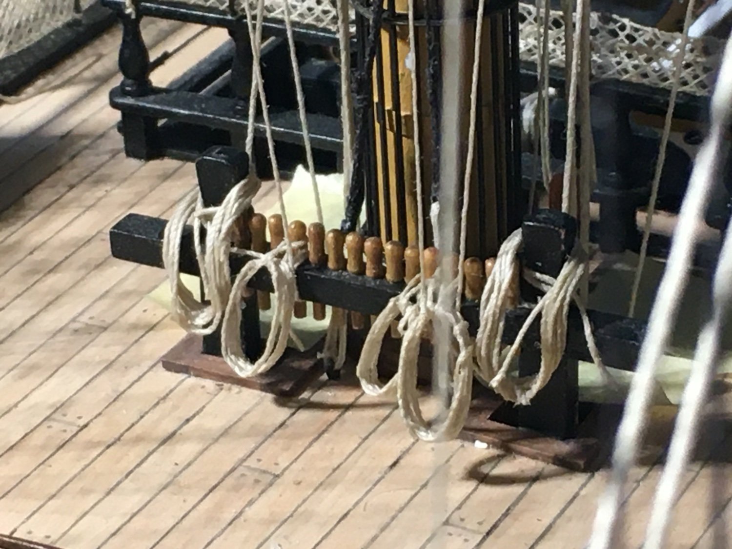
Long overdue update. I had other priorities and things have been moving extremely slow. When I found the time I was doing the rope coils. Here are a few images. I have ordered and received some flags which I will put up soon. So basically a few more coils, the flags, some fine rigging adjustments, a good cleanup and the Victory should be finished. Robert


- 527 replies
-
- 11
-
-
-
- caldercraft
- victory
- (and 1 more)
-
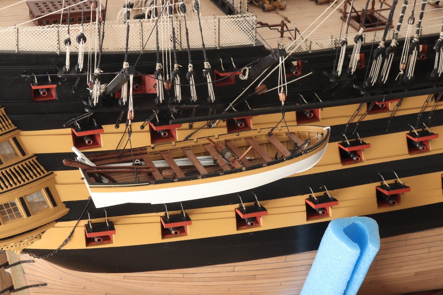
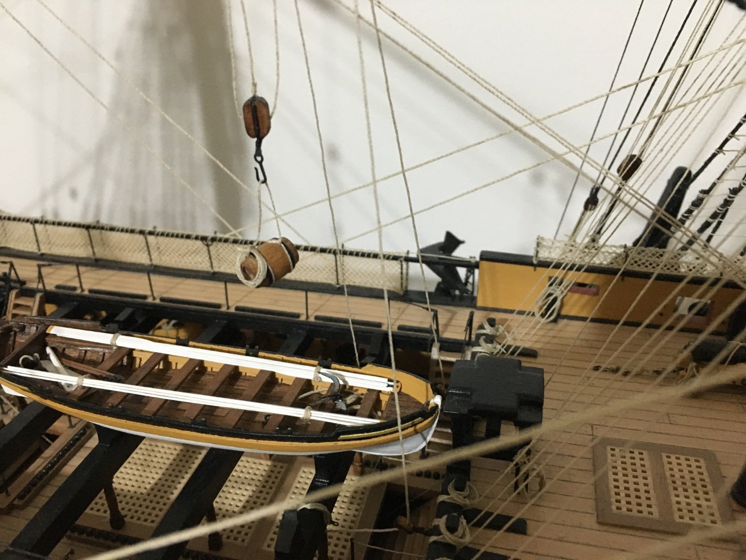
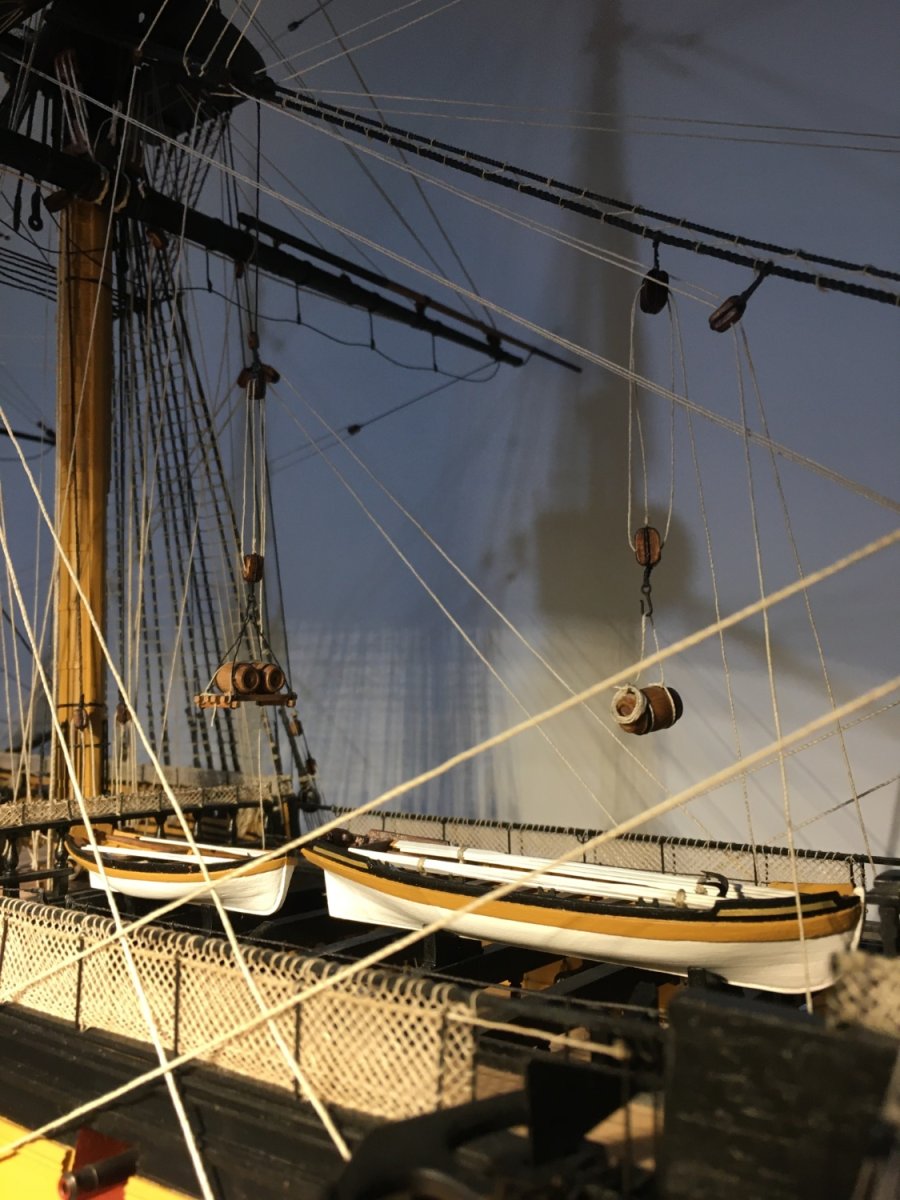
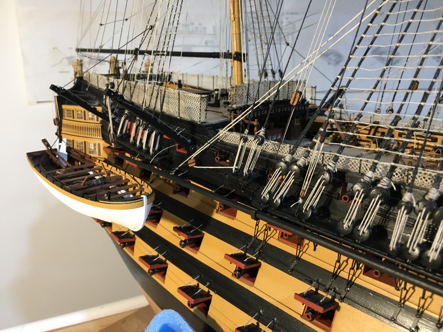
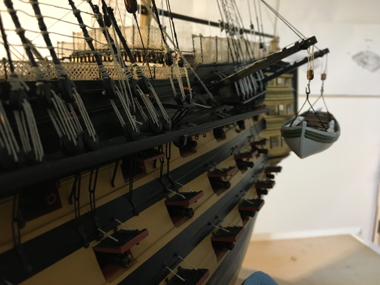
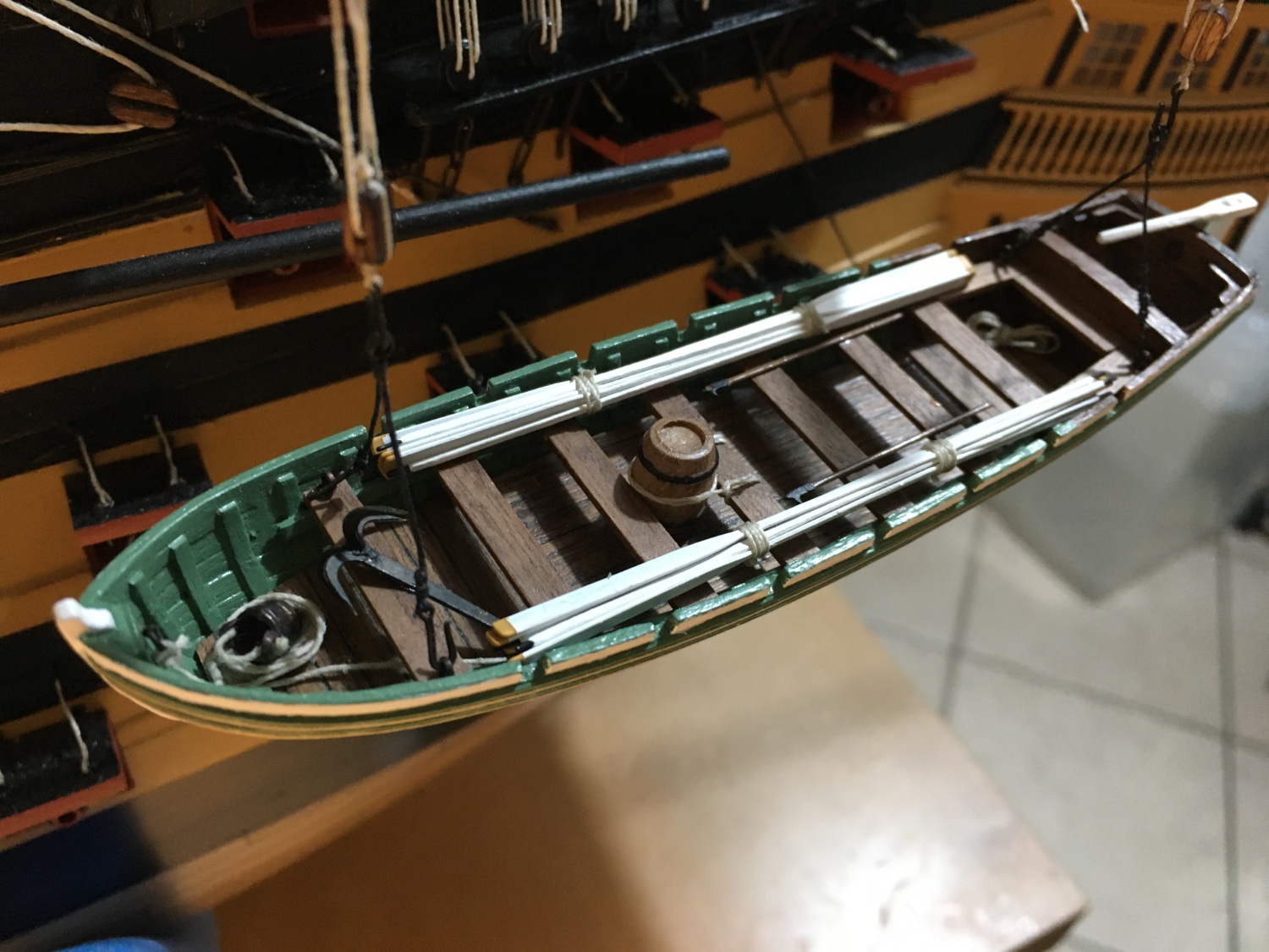
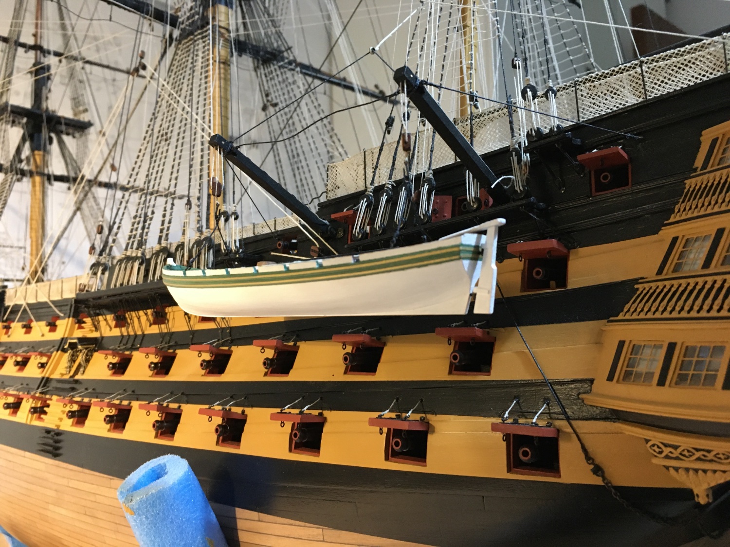
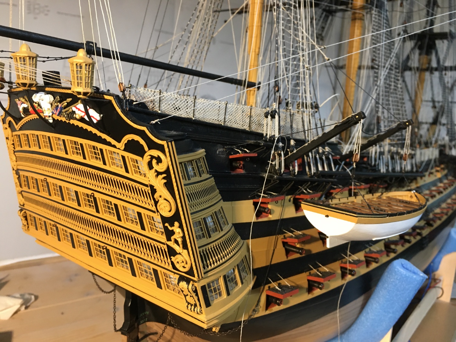
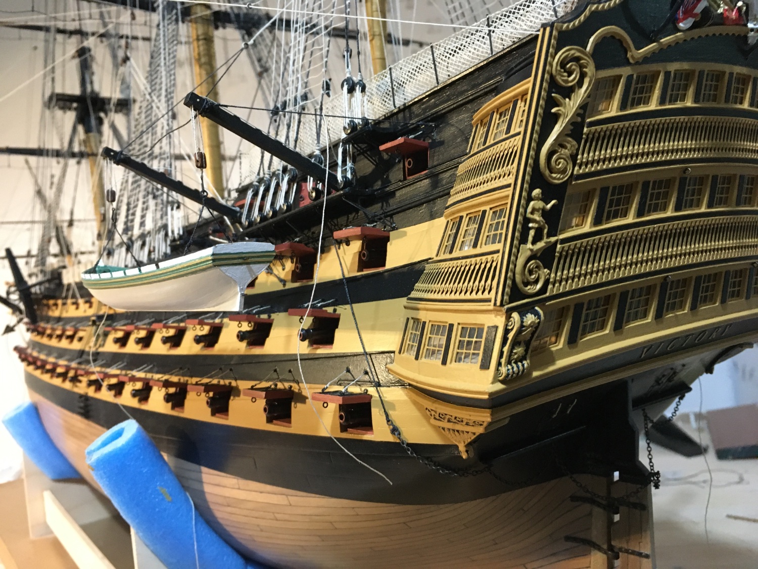
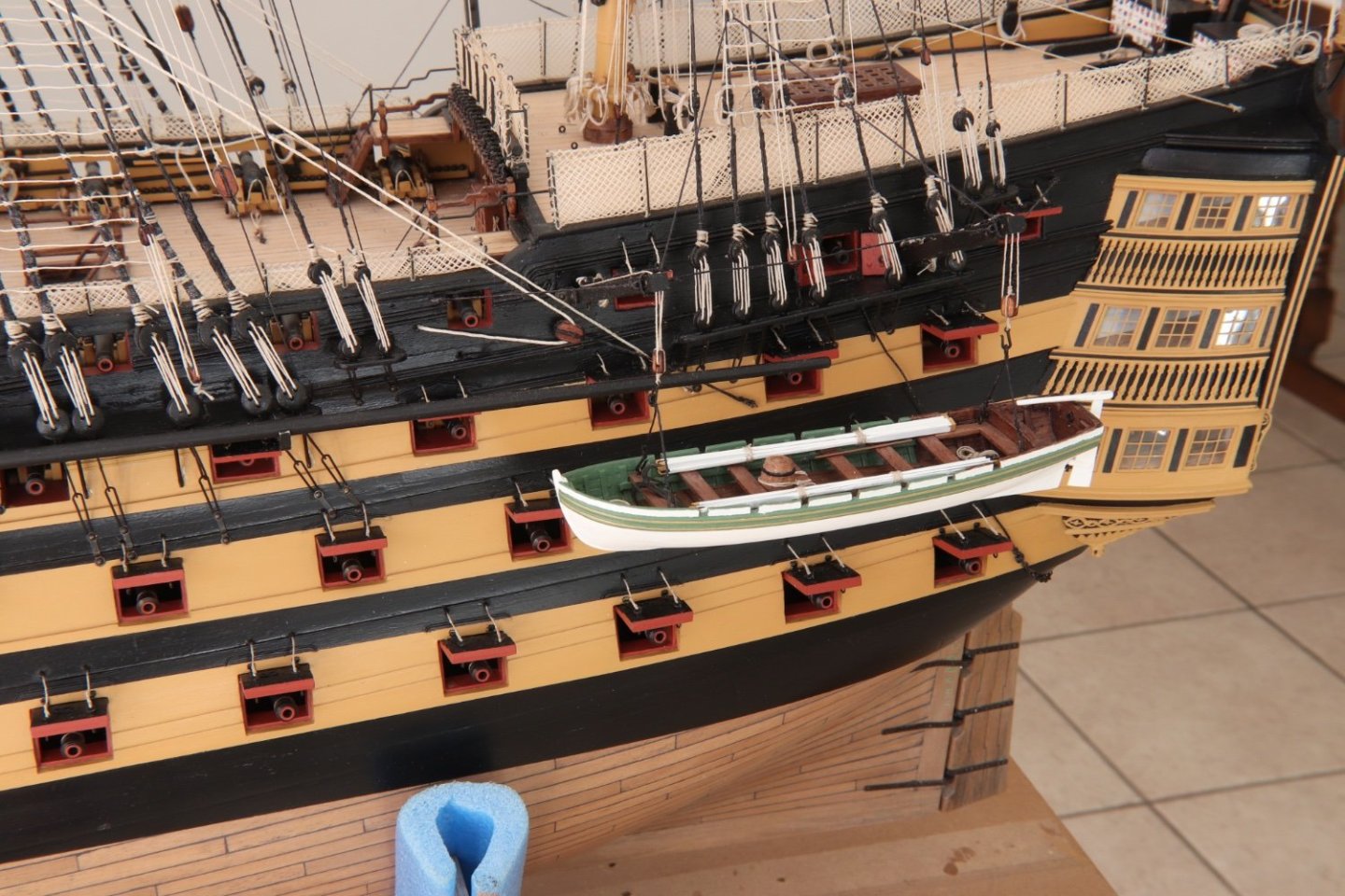
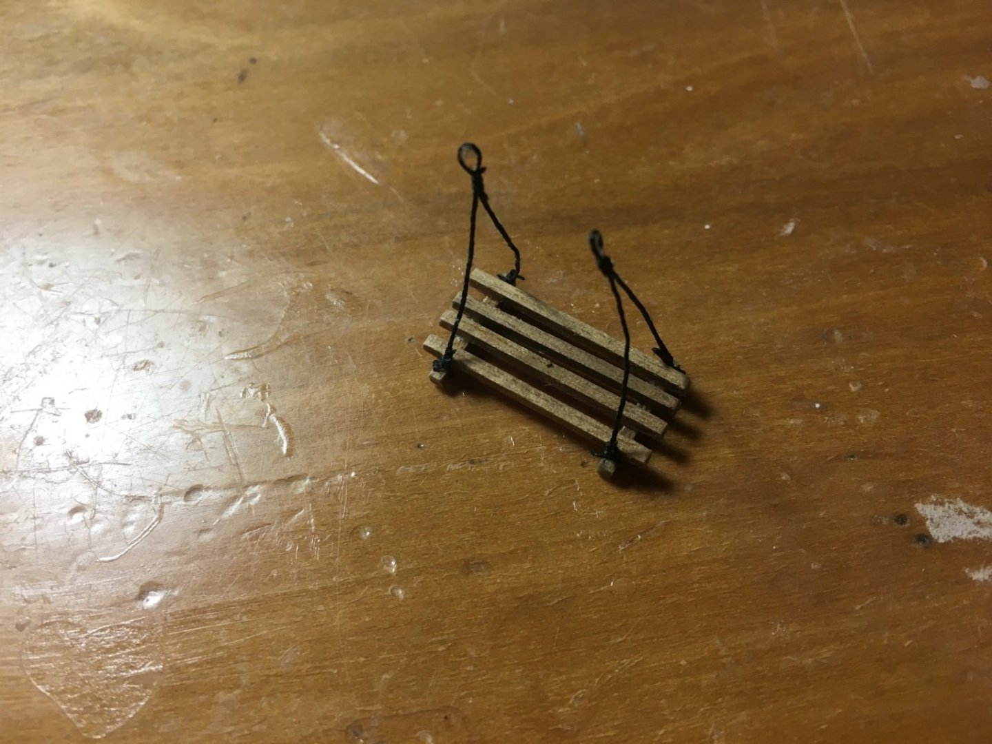
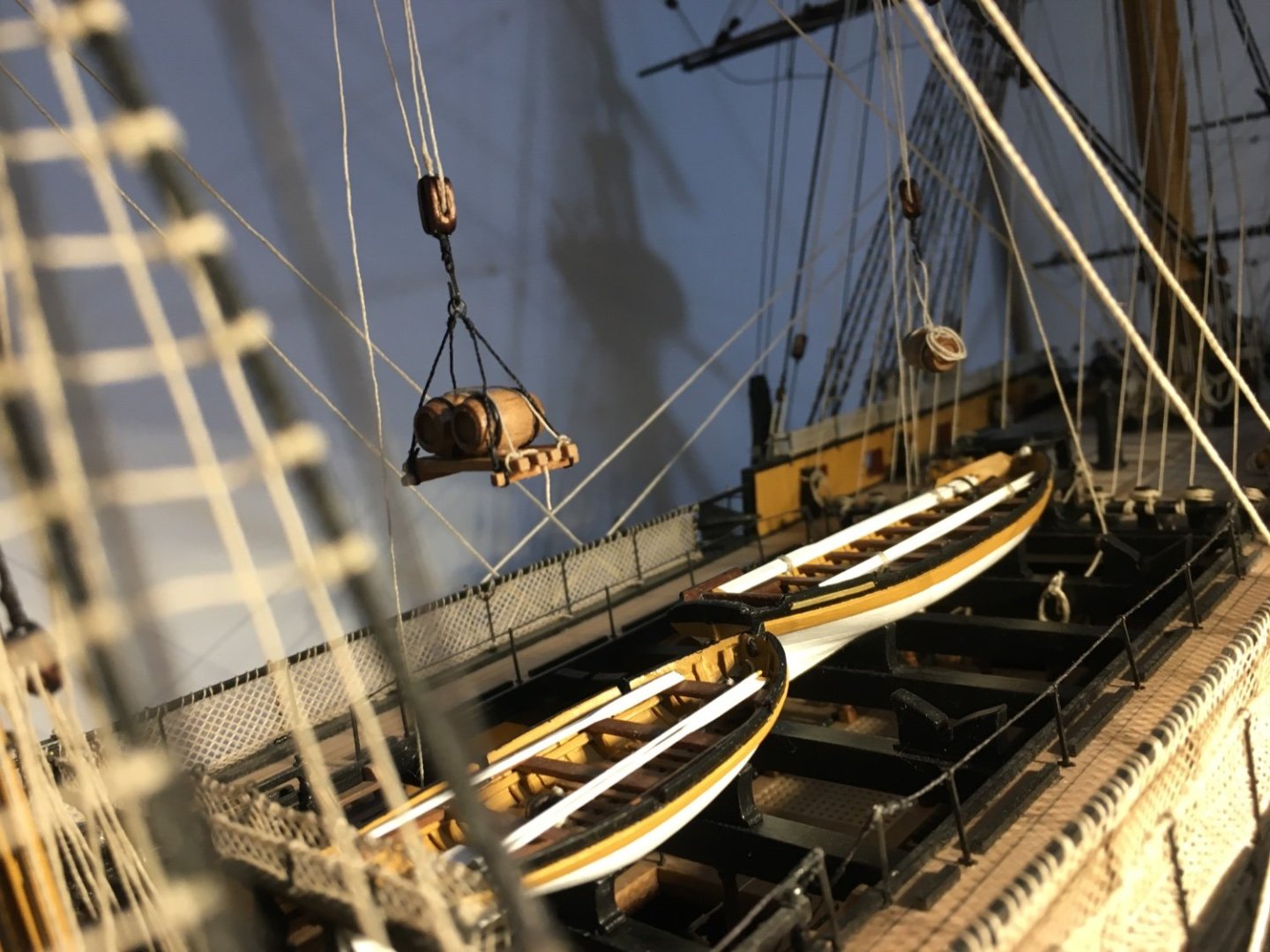
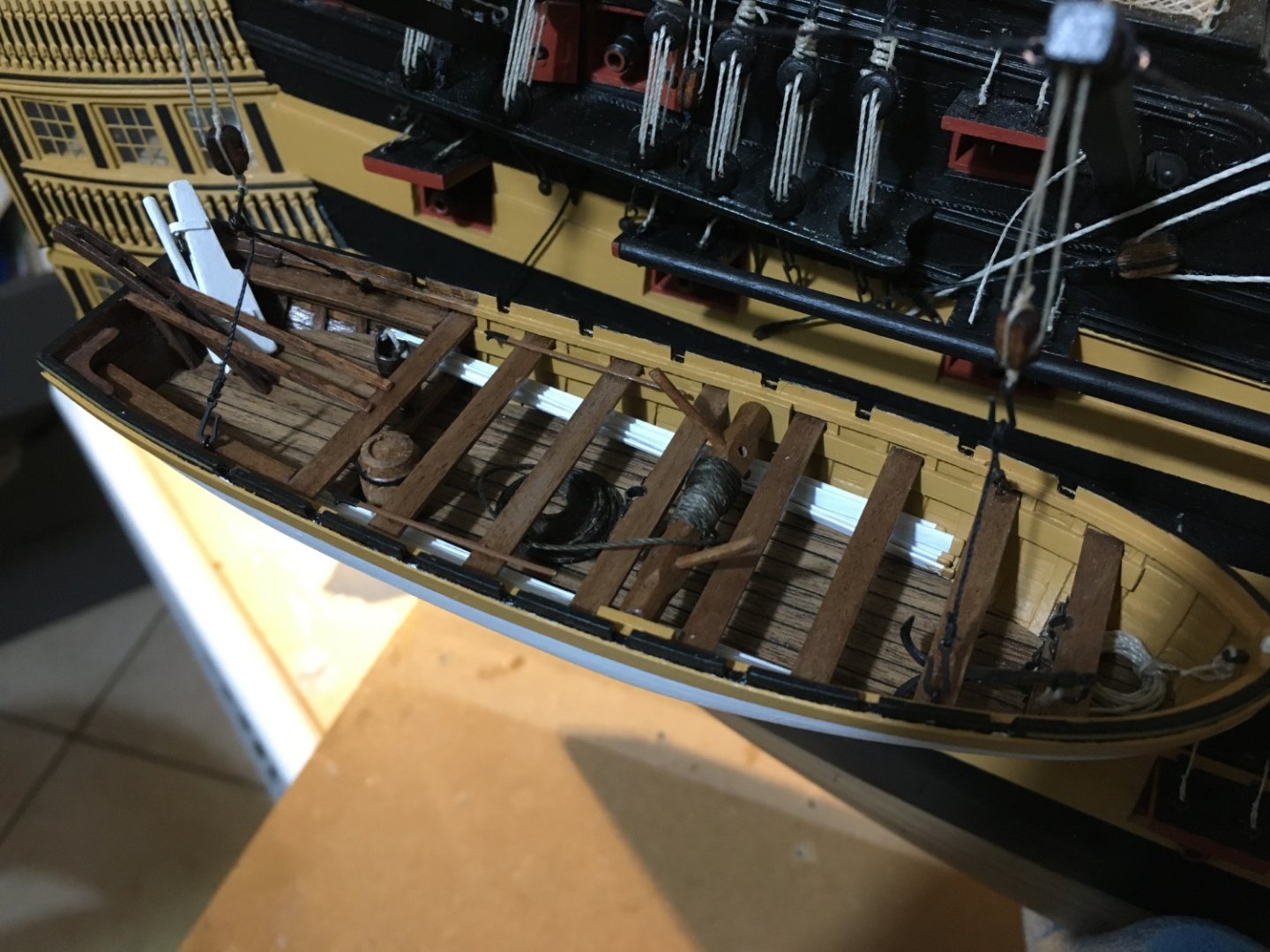
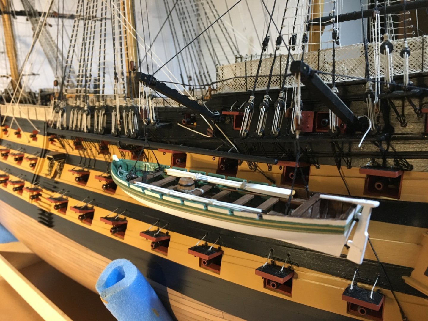
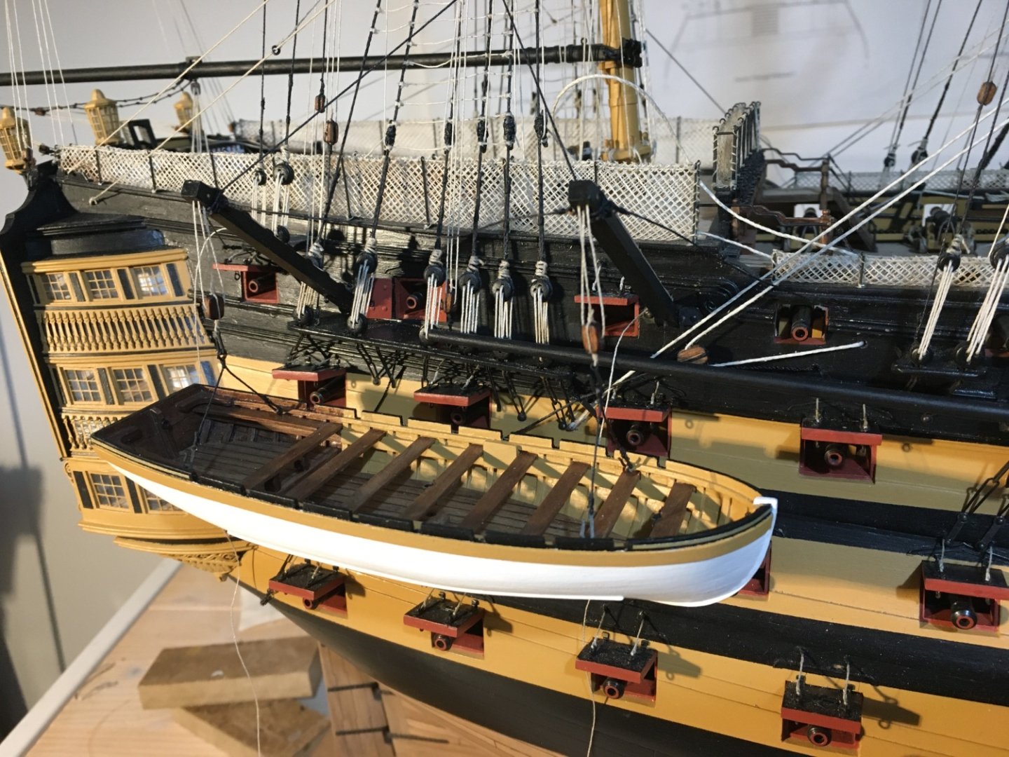
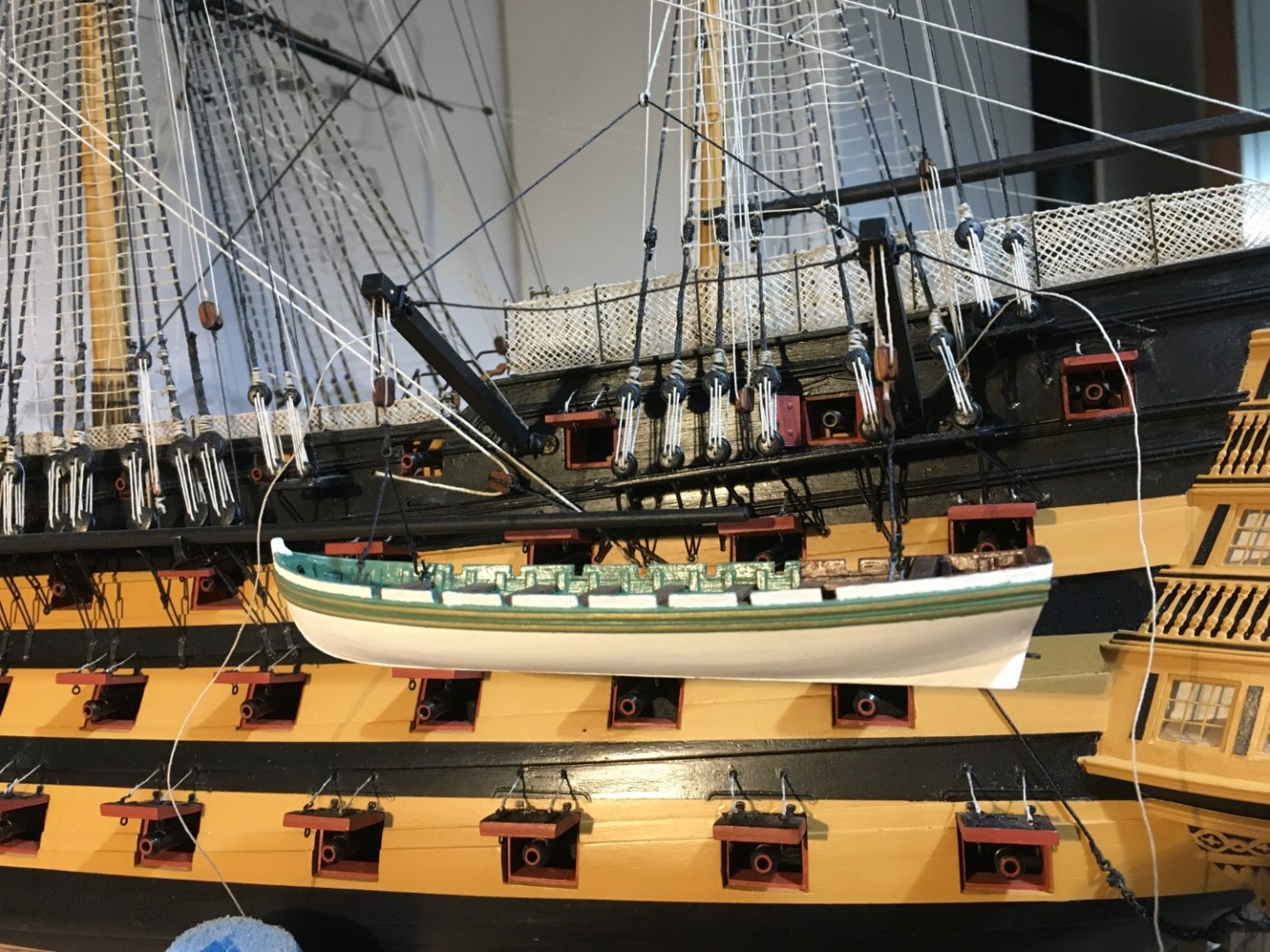
More work on the boats on the Davits. I fitted the accessories in the boats. Apart from the once supplied with the kit I added some, such as the bucket and the barrel. The Launch The Barge Robert


- 527 replies
-
- 14
-
-
-
- caldercraft
- victory
- (and 1 more)
-
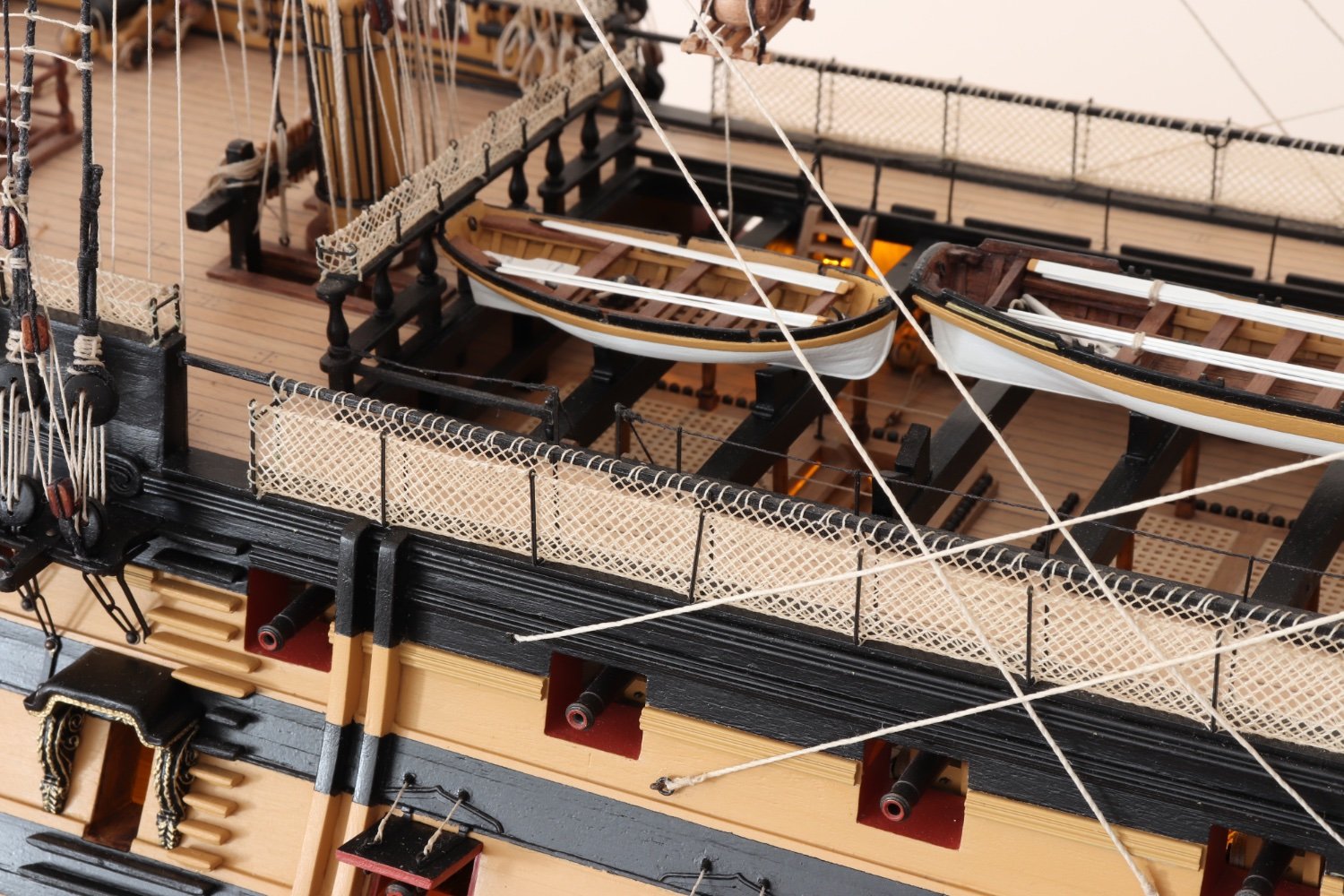
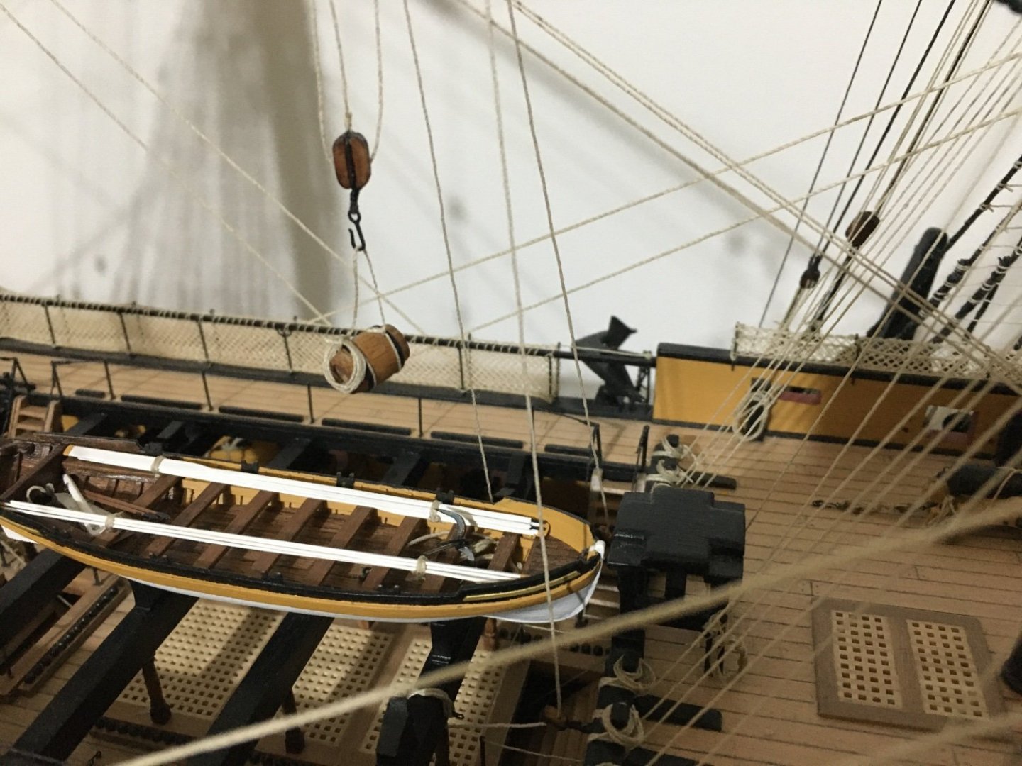
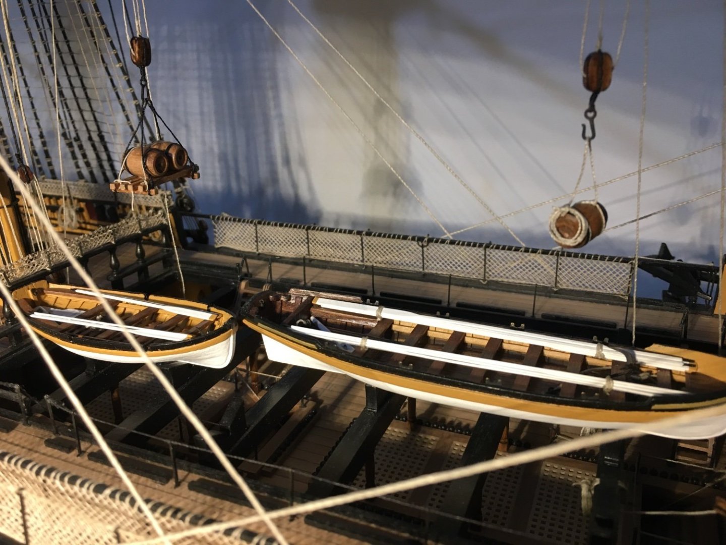
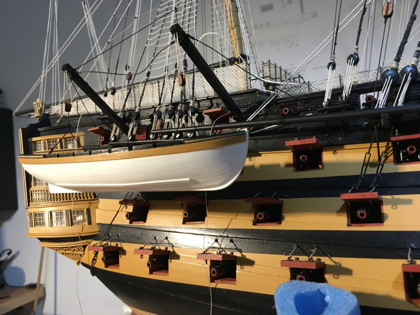
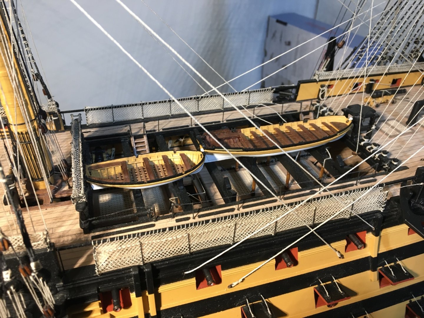
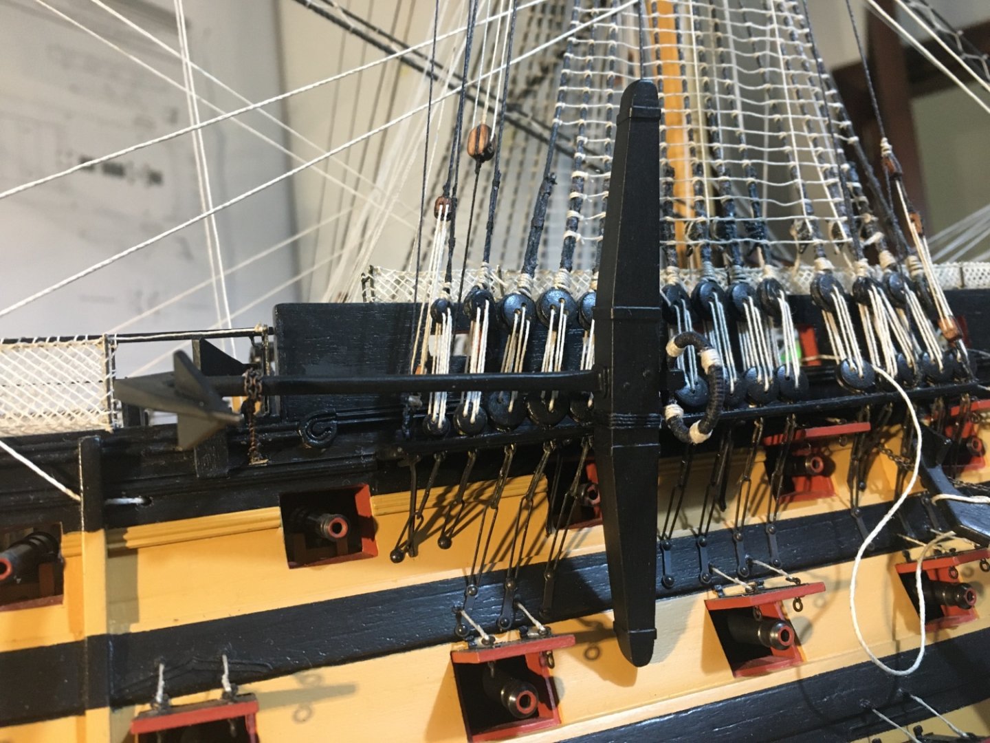
Ian, thank you again for your feedback. Even though I included the cathead stopper, I will leave the tackle as well. Sjor, thank you for your comment. I try my best as well. There are great and very skilful builders in this forum from whom I have learn a lot. Although I haven't completely rigged the anchors I continued some rigging on the davits. I had decided not to fit all four boats on deck, on the skid beams otherwise the only area that is still showing of the upper gun deck, will be obscured by the boats as well. Two of them I am hanging on the davits. The Launch and the Barge are the two boats going on the davits. I hooked them in place to find the right positions of the davit rigging and the of the tackles. I will unhook them again to add the fittings (oars, anchors, etc.) in them, which I have ready, just fit them in. The Launch on the starboard side. The Barge on the port side. The Pinnace and the Cutter to be rigged on the skid beams. I am not rigging them for now. I will leave them for the last minute as before I rig them in place I need to dust the deck under them. Fittings still to be adde in the boats as well. It's unbelievable the amount of dust the model accumulates. When finished I have to go over every inch of the model with a brush. Robert


- 527 replies
-
- 10
-
-
-
- caldercraft
- victory
- (and 1 more)
-
Thank you Ian for your reply and the images. That's what I think as well, that the large timberhead at the end of the bulkhead is the most obvious place to belay the cathead tackle. Sometimes soucing some detail is not so straight forward. Sometimes you can't find any and sometimes you find different and conflicting details. So sometimes you have to use your own judgment and go by that. But all in all the Internet is an incredible source of information. Robert
- 527 replies
-
- 1
-
-
- caldercraft
- victory
- (and 1 more)
-
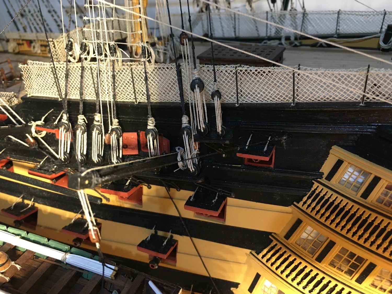
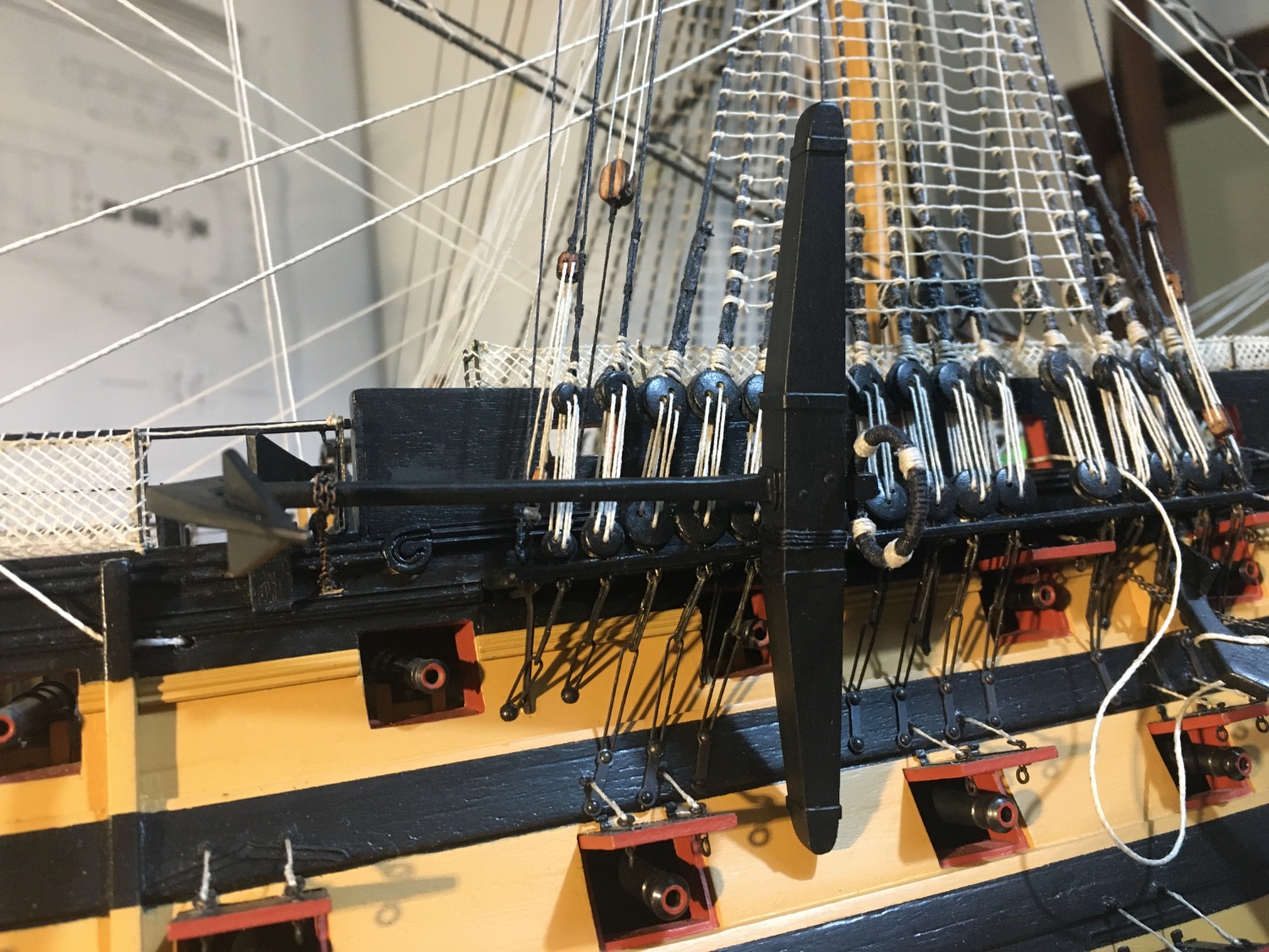
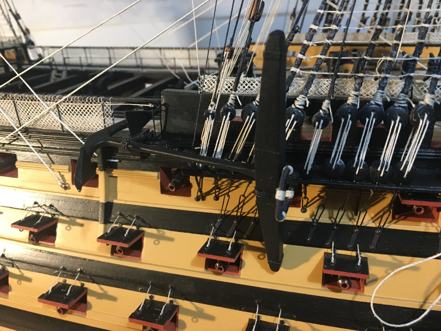
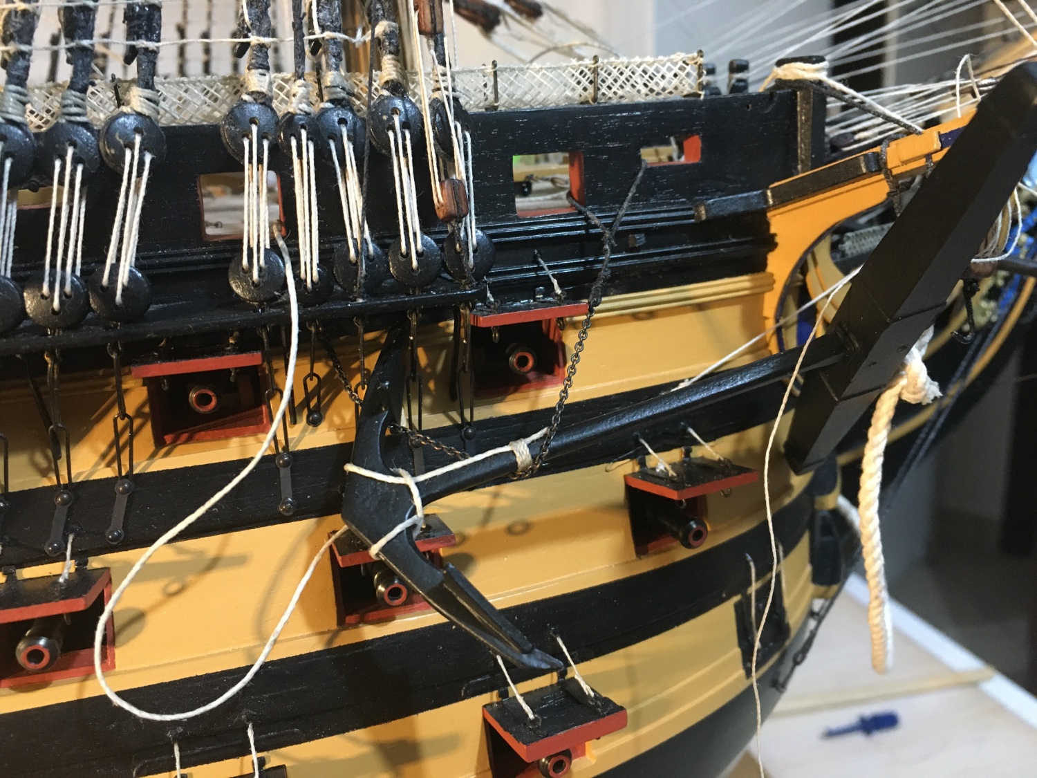
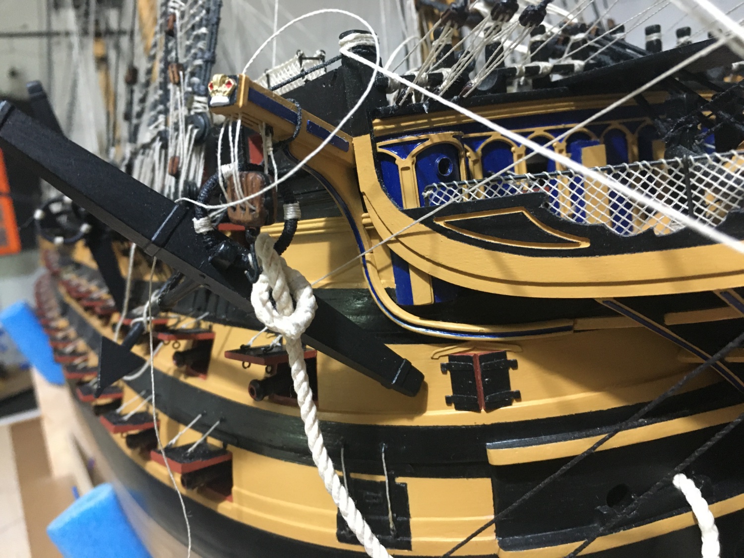
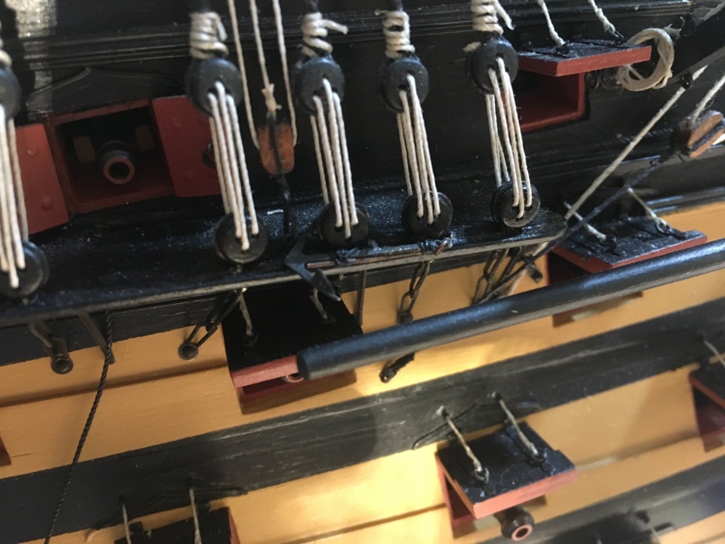
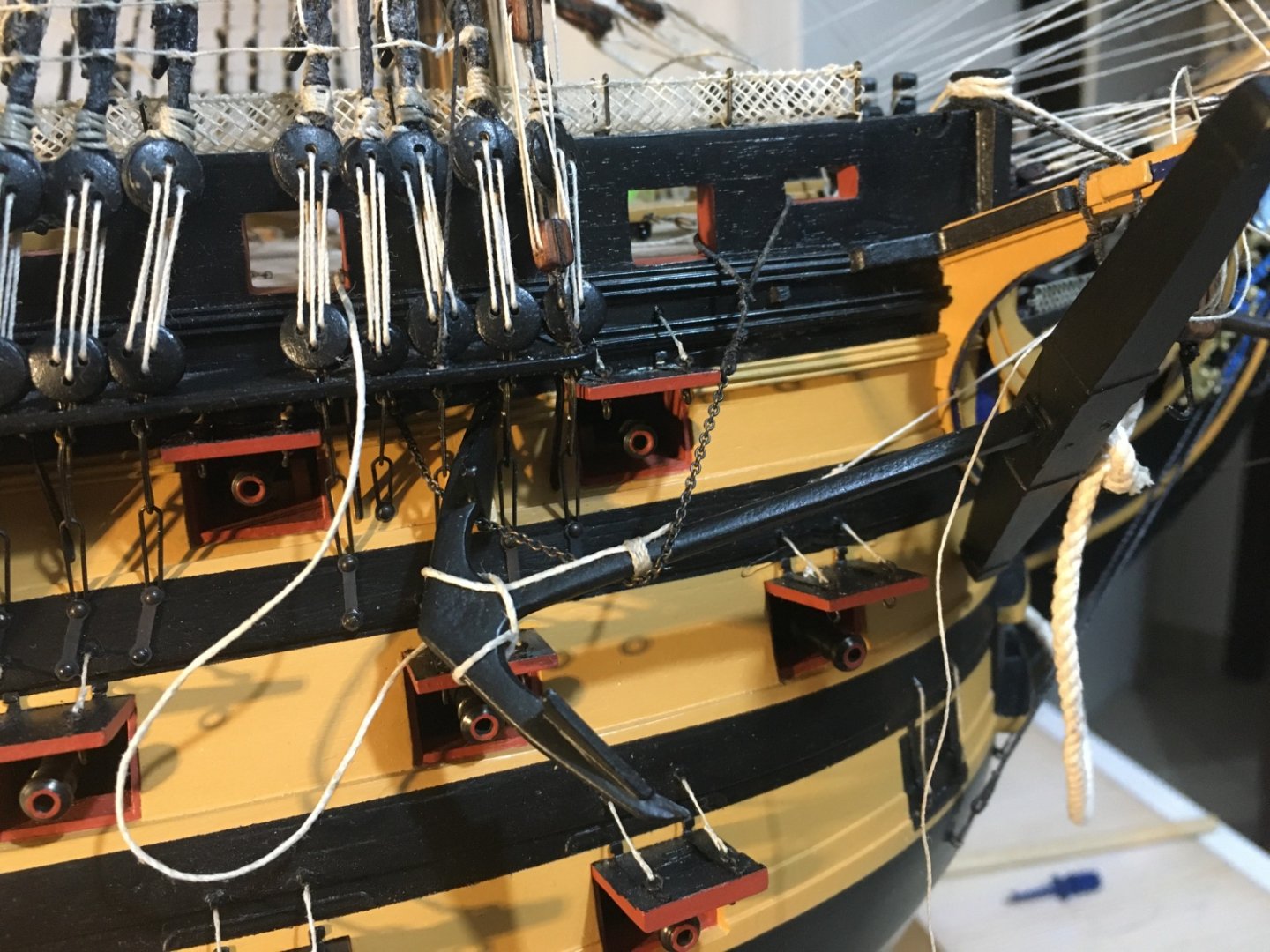
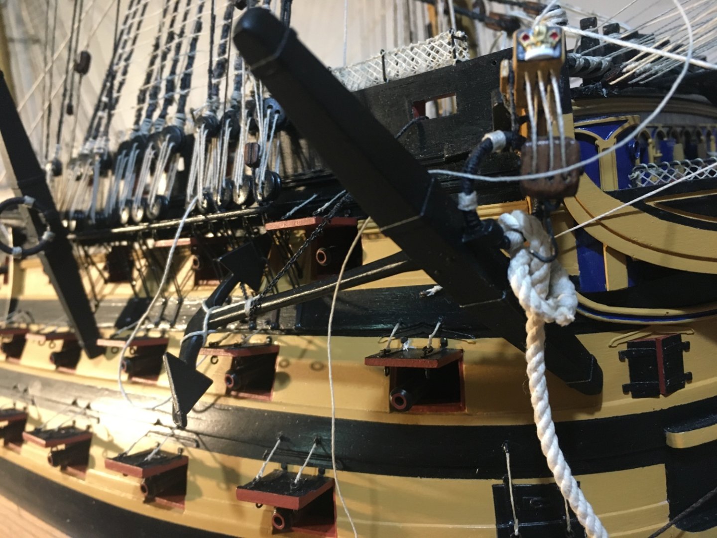
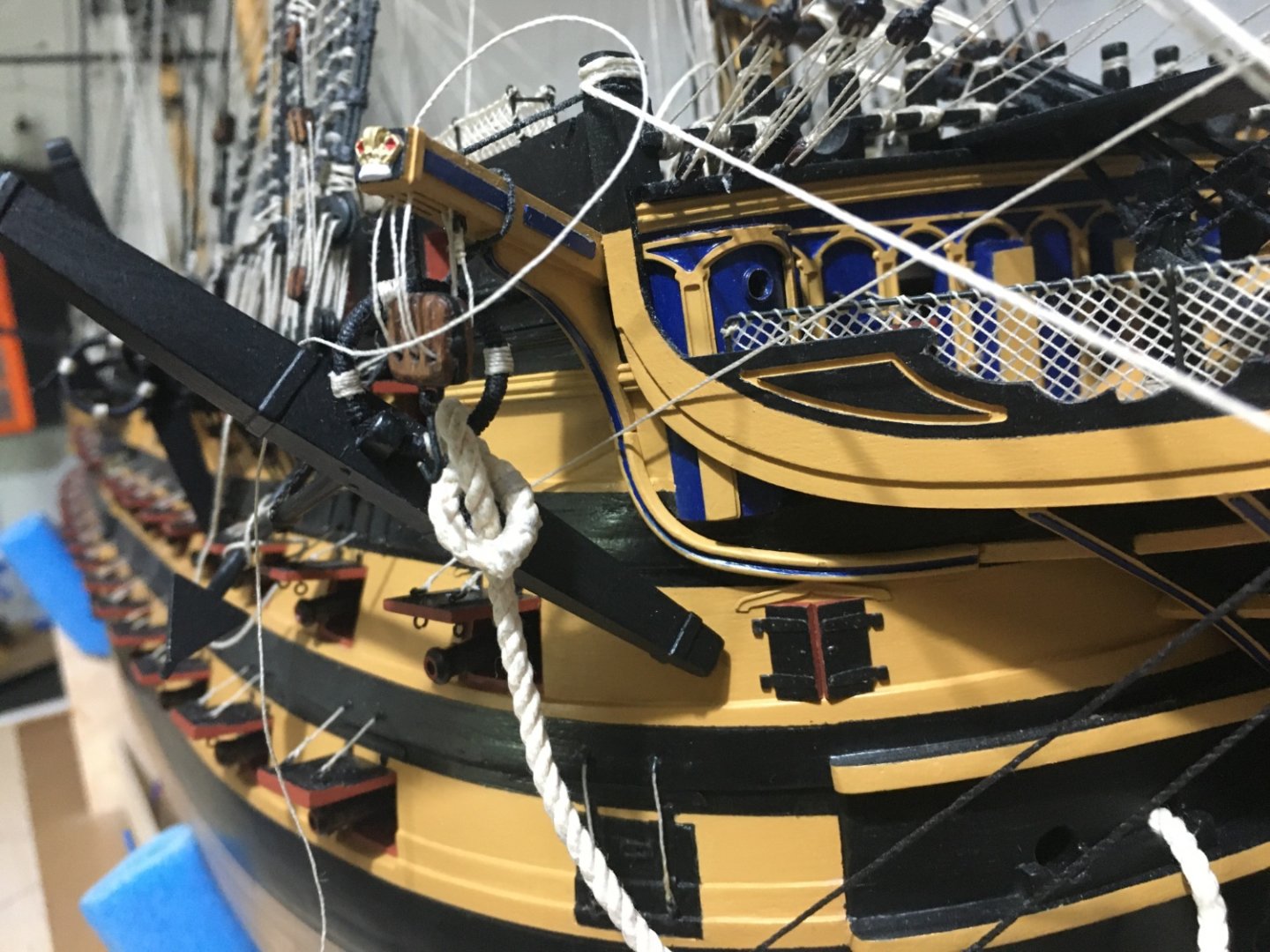
Thank you Graham. Hope it could be an idea to other builders. I found so many ideas in this forum from other builders in building my Victory. Anchors rigged in place as well. I deviated a bit from the manual's instructions on how the anchors are secured. I included some chain as seen in many of the pictures I sourced. Starboard Sheet Anchor. The Bower Starboard Anchor. Apart from the chain I also added the rope tied the the lower end of the anchor. Button I have no clue where the other end of this rope is belayed. The same with the running end of the cat head tackle line. The manual says it is to be belayed around the cathead at the cathead cleat. Shouldn't it be belayed somewhere on board behind the bulwark!!! Maybe I am wrong, I am no expert, any suggestions would be appreciated. Robert


- 527 replies
-
- 12
-
-
-
- caldercraft
- victory
- (and 1 more)