Roger Pellett
-
Posts
4,519 -
Joined
-
Last visited
Content Type
Profiles
Forums
Gallery
Events
Everything posted by Roger Pellett
-
Great video! I see that they have removed the anti-torpedo blisters. This should make the ship easier to maintain. Does anybody know where she will ultimately be displayed? Roger
-
Accounts that I have read about pilots say that they boarded by a Jacobs ladder put over the side by the crew. However, as Titanic was such a large vessel I wonder if they had a bosun’s chair handled by a block and tackle to hoist him up. Nothing but idle speculation! Roger
-
I didn't admit that in public did I?
Roger Pellett replied to Nate_A's topic in New member Introductions
Warrens, Wisconsin. Been there many to buy cranberries while driving South/North to visit my son in Indiana. Pretty place Roger -
Clipper Fan: Looking through usual sources including Mjelde’s book, I have been unable to find any hull lines for Glory of the Seas or reference to them. By hull lines, I am referring to the Naval architect’s drawing that depicts the vessel’s underwater shape. In fact, Mjelde is confusing on this point. He says that McKay carved a model of a 187 ft vessel that was changed on the mould loft floor to become a 250 ft vessel. A picture in the book shows what Mjelde purports to be the “McKay’s original builders model” for Glory but doesn’t clarify if this is for the 187ft or the 250 ft ship. If this is the correct model has someone visited the Mariners Museum to take off the lines? I enjoyed your recent article in the Journal but wondered how an accurate model could be built without a lines drawing. Roger
-
Sources: It sounds like you already have Crothers’ excellent book. if you have not already done so, I would buy a hard copy of Chapelle’s Search for Speed Under Sail. It is packed full of Clipper Ship drawings that are available from the Smithsonian Institution. A lengthy appendix includes large scale lines drawings and detailed written descriptions of Clippers. These are direct copies of William Griffiths’ contemporary Monthly Nautical Magazine. Part’s of Snow Squall’s hull has been recovered and documented in an interesting book titled Snow Squall: The Last American Clipper. The book includes lines and scantlings information for the first 18 Frames (35 feet). Other that the book contains little helpful to construct a model. In the 1884 a Henry Hall conducted a survey of the American Shipbuilding industry. His survey was published in a book titled Report On the Ship-Building Industry of the United States. Not an essential source but it does contain small scale copies of Clipper Ships. Inexpensive reprints are available. W!illiam H Webb’s portfolio of plans for Wooden Ships. This was reprinted c1990 in the Nautical Research Journal. Downloads of old articles are inexpensive. Contact the NRG office. Unlike drawings for Royal Navy warships, true originals are probably not available for these clippers, and in some cases lines drawings may have never existed as many American shipwrights designed using half models throughout the Nineteenth Century. To build the ship, measurements from the model were laid out full size and sometimes changed on the mold loft floor. This means that whatever drawing you choose to use is a copy and reinterpretation of design information made by someone. In many cases the information for recent drawings eg, Chapelle, came from Griffith’s Nautical Monthly Magazine. This might be the reason for the lack of the “Naval Hood” shown on McKay vessels as Griffiths’ magazine drawings rarely show this type of details. In other cases, Chapelle might have beset his drawings based on information taken from a half Model in the Smithsonian’s collection. It is well known that this was a source for some of his work. For these reason’s Chapelle’s The National Watercraft Collection describing the huge number of the Smithsonian’s models is a useful reference. Roger
-
Thanks everyone. This has got me thinking about several different ideas. Bottom line- I have worked out an approach using equipment available in my shop. I hope to post results soon on my Benjamin Noble build log. She requires 72 hatch boards. Roger
-
There was a category of crewmen called “idlers” that did not stand watch. This included some of the specialized ratings; the carpenter, gunner,etc. and of course the cook. I don’t believe that Marines fit into this category. Instead, they were a completely different shipboard organization. I have read that however, that they could be employed to handle lines that were belayed on the deck. Their main job when the ship was not at General Quarters was to act as a disciplined police force separate from the crew. Roger
-
Airbrush Paint
Roger Pellett replied to CLovehitch's topic in Painting, finishing and weathering products and techniques
I personally see no reason to obsess about exact color matches for paint as in the real world, paint colors are affected by many variables. This is particularly true when paints were mixed on the job. Also, different colors reflect light and weather differently, and then there’s the scale effect. For the last model that I completed I mixed my own colors. Four were required: Dark Brown topsides, Drab inboard, Red Oxide trim, And White below the waterline. While I had some General formulae, my mark 1 eyeball was the final judge. Roger -
Mini self contained airbrush
Roger Pellett replied to Bill Hudson's topic in Modeling tools and Workshop Equipment
I have a basic single action Badger airbrush, and it’s a well made tool. I have no quarrel with its quality. But, with neuropathy in my hands, I find it awkward to use as it is necessary with one hand to both hold the paint reservoir and push the spray button while making sure that I don’t get tangled up in the hose from the compressor. My current need, is basic paint spaying rather than artistic detailing. If this one piece unit actually works and has reasonable endurance, it might solve my problem. Roger -
Bruce, You’re doing a beautiful job. Like most sailors, I never paid much attention to power boats. In this case, the deck arrangement is interesting. The major seating area (the after deck) would be dangerous in any sort of seaway with unsecured folding chairs skating around and restrained only by the open rail. Chris Craft must have marketed these to appeal to buyers using them in protected waters or better tied up to a dock. Roger
-
Thanks, Dave. That’s the look that I need before weathering. I’m looking forward to making these wooden hatch boards after several years of fabricating metal parts. Roger
-
I realize that this discussion involves Silver Soldering, BUT! Various shapes of Aluminum can be found in hardware and big box home improvement stores. It is very easy to turn on a lathe and is easy to fabricate for jigs and fixtures and solder does not stick to it. Unfortunately it melts at 1100-1200F so it wouldn’t work for Silver Solder but it’s great for Soft Solder. I personally find that the lead free soft solders provide adequate strength. Roger
-
Allan, Nice work! For those without access to a lathe, a piece of brass tubing with teeth filed into the business end will also work for your trunnions cutting tool. To keep the drill press jaws from crushing it you can reinforce it with the next smaller telescoping size. Roger
-
Old eyes and shakey hands needs some advice
Roger Pellett replied to David Rice's topic in Wood ship model kits
That’s really interesting! How about a Chesapeake Bay log canoe. I can send you some plans if you need them. Roger -
Old eyes and shakey hands needs some advice
Roger Pellett replied to David Rice's topic in Wood ship model kits
Mine is apparently a result of MGUS, an acronym fo Monoclonal Gammopothy of Undetermined Significance . I have no idea what this means and apparently many Doctors don’t either. It is supposedly an extra protein in my blood. It’s presence can signal an enhanced chance of getting some really ugly blood diseases but it has been 19 years since they found it so we just continue to watch. I do have a pair of carbon fiber devices that fit in my shoes and are strapped to the back of my legs to help with the Foot Drop that comes with the nephrology. Unfortunately, as it has advanced it has ended sailing. Roger -
Hi john, Thanks for your post. Post 14 on Page 1 Is by a descendent of Theodore Grant who was the Noble’s master prior to her final voyage. Interesting reading! Do you have any additional information about your grandfather’s ownership interest or the structure of the Capitol Transport Company set up to own the ship? The Benjamin Noble’s loss stands as one of the most misunderstood events in Great Lakes history. I first read about it in a book published in the 1960’s by Dwight Boyer, the long standing marine reporter for the Cleveland Plain Dealer. Of course at that time she was still a “Ghost Ship.” I met him in the 1970’s at an event in Vermilion, Ohio never dreaming that I would live within 20 miles of her loss and would sail scores of times in and out of the Duluth Ship Canal that she was trying to reach. Of course, her wreckage was found and surveyed in 2004, but authors are still cranking out Dwight Boyer’s 1960’s story in new books. I will be the first with a Naval Architecture background and a set of her original drawings to logically analyze her loss. I would like to set the record straight. Stay tuned, Roger
-
Old eyes and shakey hands needs some advice
Roger Pellett replied to David Rice's topic in Wood ship model kits
Bob, Welcome to the club. I have peripheral neuropathy in both my hands and feet. I have had it for some degree for almost 20 years. Oddly enough, I believe that ship modeling is actually helpful. My brain seems to keep rewiring itself as I use my hands going forward. David, I agree that building larger scale small craft might be a good choice for you. Chapelle’ History of American small craft provides a wealth of ideas. I have long been interested in building a series of related small craft to a standard scale of 1:32. I chose Warship Boats. I have finished three examples: a 1900 40ft Standard Steam Cutter, a 26 ft motor whaleboat, and a 32ft Early Eighteenth Royal Navy Longboat. A caveat; Small Craft have thin planking and very small scantlings. This sort of defeats the idea. My three models are not POF they have hulls carved on the outside and hollowed out on the inside with frames added. IMHO they are still quite convincing. So, I second Bob’s idea of building “dugouts.” The NOOTA with its bold colors is a great idea. Or, if you want to build a model with some rigging how about a Chesapeake Log Canoe? Roger -
Planking Book?
Roger Pellett replied to BWDChris's topic in Building, Framing, Planking and plating a ships hull and deck
An originally ballyhooed reason for buying POB kits instead of solid carved hull ones was that they were like “building the real thing.” So, try doing what real shipwrights did BC (before CAD). Make a planking expansion drawing! On a sheet of paper, draw the profile of the hull. Next draw lines perpendicular to the keel upward at the location of each bulkhead. Next cut a handful of paper strips. Wrap a strip around each bulkhead from the keel rabbit to the sheer line and make a mark there. This will measure the girth of each bulkhead half. Plot these girth’s on your drawing at the bulkhead location lines, and connect the points with a curve. This is an accurate picture of the area that you have to cover. Next, plot any known planking lines such as the Wales on the drawing. You can now play around on the drawing with different planking schemes. CAD users can easily erase schemes that they don’t like. Otherwise, make several copies. Roger -
I agree Michael. Many years ago Eric Ronnberg, a model maker and historian who I greatly respect wrote that jigs and fixtures should not be too nicely finished as they risked being kept and for something that they were not designed for later on. I find them indispensable. Roger
-
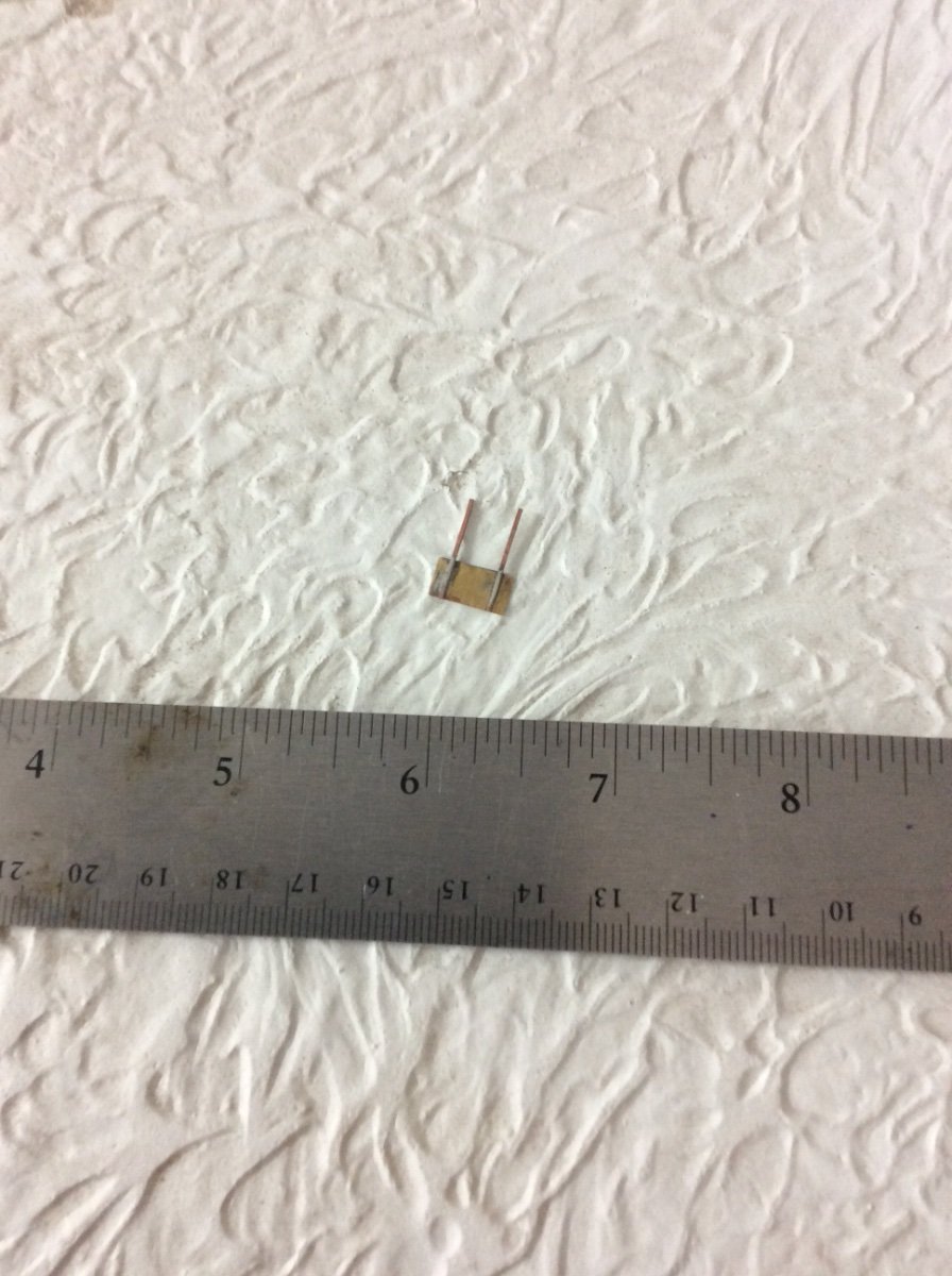
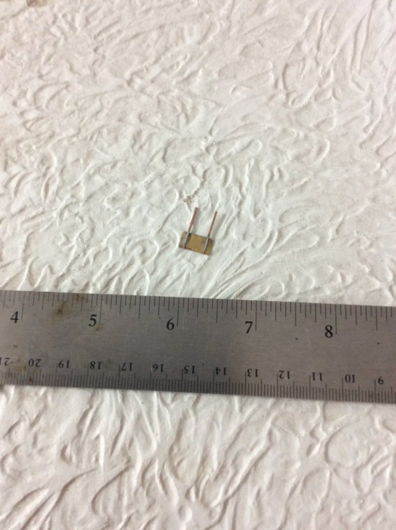
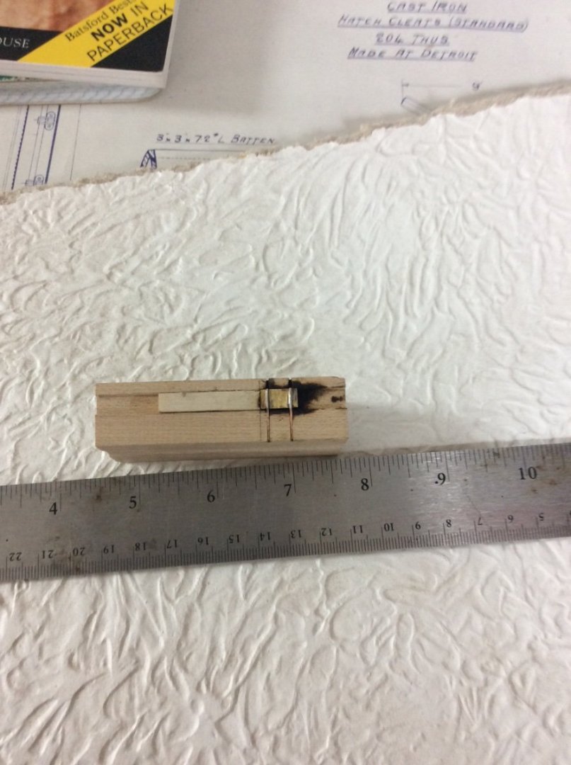
Freeing Ports: Scratch Building is a series of small models within the overall model. Each of these small models involves the following thought process: 1. Identify the item to be built as a small model 2. Determine what the item looks like or in some cases what did known items used on this other vessels in this same time period look like. 3. How do you plan to represent the item at the required scale; ie how much detail to you plan to include. 4. What materials and techniques will provide a quality reproduction. The following project completed during the past several weeks illustrate this process: Bulwark Freeing ports The bulwarks are pierced with eight freeing ports. These are rectangular, each closed by a flapper plate hinged from the top so a head of standing water on the deck would push the flapper open and drain the deck. Gravity would also open the flapper if the vessel heeled. At 1:96 scale, these flappers are quite small 7/16” x 3/16”. The plates were made from .010” brass which was temporarily glued to a piece of craft plywood. They were then easily cut on my Byrnes Saw. At the small scale, I could only simulate the hinges. I decided to show strap hinges. The straps were made from 22 gauge square copper wire. The two straps needed to be precisely soldered to the flapper plate. Once located they had to be rigidly held in place while being soldered. I therefore made the fixture shown below from a block of wood. The large groove was cut with a 3/16” milling cutter in the Sherline mill. The strap hinges were to be 5/16” apart so two groves spaced at this distance were cross cut on the Byrnes Saw. The plate and straps were then dry fitted in the fixture and the plate was shifted until the spacing from the strap to the plate edge was exactly the same on each side. A wooden stop to register the plate in the groove was then glued in place. The square wire strap material was tinned with solder. When heated with the soldering iron I got a sound joint. The copper straps will be trimmed to length when they are finally soldered to the bulwarks.
-
The basis for any ship model worth displaying is a correctly shaped hull. Correctly shaped means that it reproduces the “lines” of the actual vessel in miniature. The noted Naval Architect L Francis Herreshoff once wrote an article where he noted that models representing particular named vessels with misshapen hulls are evil things. If Revell used the same mold for both Kearsarge and Alabama one is not worth buying, at any price. Roger
-
Congratulations on the new baby Keith. My wife is the official cute baby evaluator in our house. She awarded your new grandson 5 stars. Roger
-
Spectacular models! Alabama’s straighter stem and small radius forefoot would produce finer forward hull lines. Roger