Roger Pellett
-
Posts
4,519 -
Joined
-
Last visited
Content Type
Profiles
Forums
Gallery
Events
Everything posted by Roger Pellett
-
Printable scale rulers
Roger Pellett replied to FlyingFish's topic in Modeling tools and Workshop Equipment
Bob, I don’t know what your special requirement is that cannot be met by a triangular architect’s scale like Bob Cleek describes above, but here is another possibility. BC (Before CAD) or more precisely before 3-D digital modeling, Engineers used to build models of industrial projects. These were plastic scale models with structural steel, equipment, and piping. The models were made from the project’s drawings and were used among other things to check for interferences. I once had to make a “takeoff” of the piping for a coal gasification plant from one of these models so that we could order materials prior to issuance of the final drawings. The model was located at the Engineer’s office. The Engineer had several Steel Scale Tape Measures. Unlike the architect’s scale, there was a separate tape measure for each scale. These tapes made quick work of an otherwise tedious job. If you can find one of these to the correct scale it would be ideal for ship modeling. Roger -
Keith, Welcome back! As they say, age is just a number, but as the numbers creep up visits to the Doctor become more numerous and allow us to keep modeling. Congratulations on your new grandson. Here in the US, “gender reveal” parties are in vogue; some quite elaborate. Fortunately, my wife and I have avoided having to attend one of these. Roger
-
Question about Titanic kits
Roger Pellett replied to David Enghauser's topic in Wood ship model kits
Not a kit builder, but why buy a POB kit and go through the effort to plank the hull if the end result is a steel hulled ship? If you want to replicate one of the classic “Steamship company” models of long ago with smooth hulls than effort and some sort of goop will required to hide the planking. On the other hand if you want to make the effort, the planked wooden substrate would allow plating, I like shellac impregnated paper, for a realistic appearance. A plating expansion drawing is available on Titanic websites. But! The moulded side shell plating seen on the plastic model kits offered is way over scale; more like armor plate. If Titanic had been plated with plating that thick she would not have sunk. Roger -
OR- Display the model with the sails furled!🤣🤣
-
I am thinking of using scored deck planking for wooden hatch covers on my present project. Planks would be 6in wide or 1/16in at scale. I have found some Model Shipways scored basswood with 3/32in planks that might work. My question: how thick is this decking? Roger
-
Here is a scheme that I used to make flags printed in rice paper. It might work for you. You will need: An airbrush A Shop vacuum or similar vacuum with hose A piece of frosted Mylar drafting film A homemade vacuum box and frame (photos below). Paint- the color of your sail Silkspan Draw the patterns on the Mylar and cut out the designs. Tape the silkspan to the frame, mist with water and let dry over night. Silkspan should be drum tight. Place the frame with silkspan on top of the vacuum box, and turn on the vacuum. The vacuum should suck the patterns tight against the silkspan. Spray with paint the color of your sail with the vacuum running. If done properly the lines between the symbols and the sail will be crisp but as Allan says the paint will bleed through the silkspan. You can overcome this by painting two mainsail images and laminating the result. Roger

-
You Richard Bong, a WW II Ace who flew a P-38 was from Poplar, Wisconsin, a tiny town about 25 miles from Duluth. I believe that the art on the box depicts his plane. For many years, a P-38 sat in the Poplar city park. Several years ago, the plane was removed, and taken to the Duluth Airport where is was restored by members of the Minnesota Air Guard. Bong’s widow, Marge was instrumental in establishing a Veterans Heritage Museum in Superior, Wisconsin, across the Harbor from Duluth. The plane is the centerpiece of their collection. Roger
-
Bob, Re: your post #7 above. Well said! I don’t remember, where I read it but a master model has written about the need to “think in scale.” This can be helped if you are building to a common scale and are using an architect’s scale to measure things. I also find it useful to quickly relate scale sizes in my head. For example, my current project is 1/8”=1ft or 1:96. That’s close to 1:100. If I am selecting a piece of wire to make an eye bolt and grab a piece of 1/32in dis wire; in my head- 1/32=.032. Move the decimal point to the right 2 places: 1:1 scale is 3.2” dia; way over scale! Reasonable diameter of wire to scale is .0032in. Roger
-
Benjamin Noble’s wooden hatch covers were typical of those used on cargo vessels of the day. Each hatch was covered with about 12 separate covers, each cover made up from wooden planks. I’m not trying to make these look abused or beat up. I am looking at a paint scheme to differentiate the different planks within each cover- your “paint only approach.” This will challenge my limited artistic skills! Roger
-
Ancient galley rams discovered - photos
Roger Pellett replied to Louie da fly's topic in Nautical/Naval History
Where is Egdi? -
Andy, Thanks for the tip. No I have not. The wooden hatch covers will be an interesting new project for me. I have absolutely no experience weathering. Roger
-
Thank you Wefalck. I am working on hatches and need to go back and review your deck painting scheme. I need to figure out how to simulate weathered planking for the boards making up the hatch covers. Roger
-
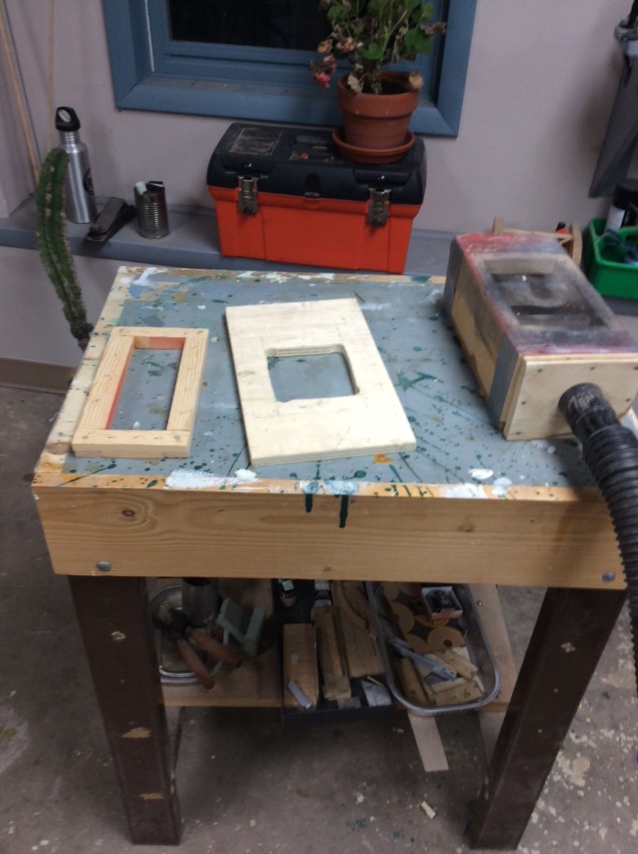
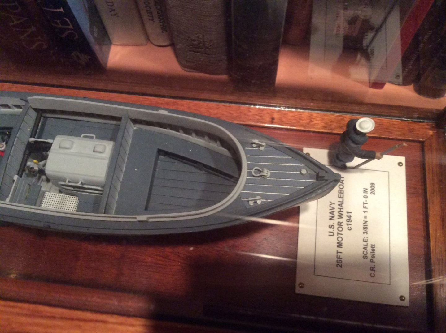
Not exactly an answer to the question but some might find this useful: Here is a system that I used to simulate the WHITE seam compound used in the deck seams of a US Navy WW II era motor whaleboat. 1. Using my Byrnes saw, cut grooves spaced to planking width in a piece of craft plywood. 2. Spray piece with white paint, and lightly sand using a sanding block. 3. Insert a piece of thread, color unimportant, into each groove. 4. Spray piece with Navy deck blue. 5. Remove thread, cut piece to shape and attach to model. Results:
-
Great photos, thanks for posting.
-
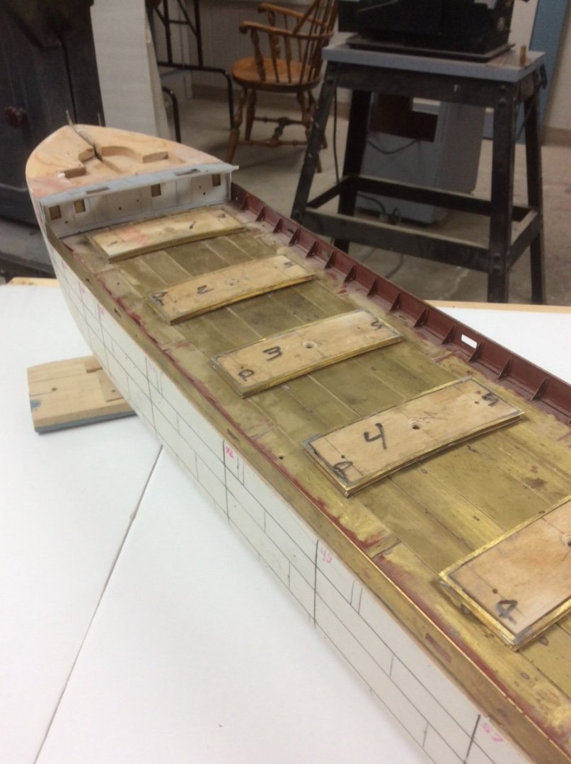
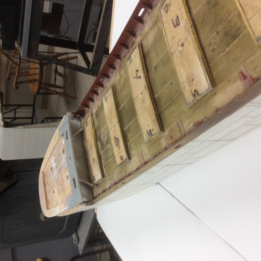
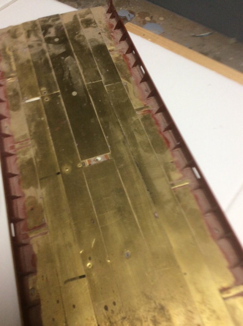
The Main Deck: Lake freighters with their long narrow hulls are dominated by their long parallel mid bodies; a long box that carries the cargo. This was capped by the main or spar deck. Technical papers of the time criticized the design of these vessels for their lack of internal watertight subdivision. Specifications for steel merchant ships usually specified the number of compartments that could be flooded without sinking the vessel. (Titanic’s owners required her to be a “two compartment” ship.) The Naval Architect’s job was and still is to space watertight bulkheads accordingly. Great Lakes vessel were not subdivided. There was a watertight collision bulkhead beneath the forecastle and another immediately forward of the boilers. The rest of the hull was one long cargo space. While this allowed vessels to be quickly loaded and unloaded quickly, flooding of the cargo space sank the ship. On the lakes’ restricted and often foggy waters collisions and sinking were common. Benjamin Noble’s main deck was pierced for six hatches. I will discuss the hatches in a later post. An unusual, by 1914, design feature were four foot high bulwarks enclosing the main deck. Vessels designed for bulk cargo trades; ore, coal, and stone, had open pipe railings instead of bulwarks. Benjamin Noble’s bulwark turned the main deck into an opened topped box to protect a deckload of pulp wood logs. The photos below show the main deck and bulwarks for the model. Built several years ago, one photo shows the deck dry fitted into the hull. The hatch coamings are just set atop the deck in their approximate locations. The assembly began with a wooden framework with deck frames cut to the correct camber. A deck of thin craft plywood was then added. The brass deck plating was attached using pressure sensitive 3M transfer tape. Unlike the hull plating which uses the “in and out” system the deck is clinker plated. I normally don’t like PSA tape but is has now held up for several years and edges are anchored by the bulwarks and will be further anchored by the hatch coamings. The bulwarks were fabricated from .010in brass sheet, cut to shape. The sheer angle was cut from square brass tubing, ripped on the Byrnes saw. The cap rail is 1/16in round brass tubing slotted on the Byrnes saw. The triangular supports began as .010in brass sheet cut into squares. They were folded over an aluminum pattern before being trimmed to their final shape in the mill. I used an old fine tipped Bernz O Magic torch perfect for our needs to solder everything together. I tried to buy a replacement- no longer made. The bulwarks are pierced with a number of openings that need to be fitted with closures, reinforcements, etc. and the hatches need to be detailed. This work will complete the main deck. Roger
-
Greetings from the Highlands
Roger Pellett replied to Swordfish073's topic in New member Introductions
Ian, Welcome to MSW. Roger -
I would suggest that you continue your sand, fill, paint routine and see what happens. Sand using a backup block behind your sandpaper. You can make special sanding blocks for concave surfaces from dowels, etc. Use an open coat coarse paper and change it as soon as it clogs up or stops cutting. If you sand away most of your paint and filler that’s ok. Once you have sanded, fill again, sand and paint. You May have to repeat this process more than just a few times but the hull should begin to assume a shape with “fair” curves. Roger
-
Tim, Before you launch this beauty, you should built a 1:48 scale destroyer escort that can drop model depth charges! 😀 Roger
- 72 replies
-
- 3
-

-

-
- Seguin
- BlueJacket Shipcrafters
- (and 2 more)
-
If you get vetoed on the vegetable steamer, you can hook your soldering iron into an inexpensive light dimmer switch to control temperature. You can also your wet your wood strips and nuc them in a microwave. The last, probably as popular as using the vegetable steamer! Roger
-
Steven, Your aftercastle’s second iteration looks logical to me. I believe that these old vessels can be considered as two separate parts; the hull, and the structures built on top. It was not until the 1500’s that the castles were integrated into the hull form. Projecting the bottom of the aftercastle would involve cutting into and weakening the hull. Roger
-
I assume that the anchor is from a kit. Most kit metal fittings are some sort of “white metal.” This can be one of several lead or pewter based alloys. These alloys are easy to damage with soldering heat as their melting point is close to or even less than that of the solder. Also, solder may not bond to some. Thickened Epoxy should work well in this application. I like JB weld. Roger
-
Beautiful job- Difficult subject! i certainly hope that you will include a few posts about rigging. Roger
- 166 replies
-
- 4
-
-
- Maine
- BlueJacket Shipcrafters
- (and 1 more)
-
If you are willing to spend the time and effort to accurize the saw it MIGHT work. There are two features integral with the saw that you should consider as you will not be able to change. Arbor size: As you obviously know this will determine the blades that you will be able to use. High quality model makers saws use machinists slitting saw blades. Cheaper mini table saws often come with blades with very low tooth count and a lot of “set.” Will you be able to replace the supplied blade with something better. Power: You can’t have enough. When buying tools, Amazon is often poor at describing technical features that let you determine if they (the tools) will meet your needs. Since you have a full sized table saw, have you checked the full range of blades that might be available? A fine toothed blade without set to the teeth used in a full sized saw is a viable alternative to a mini saw. Way back when, Sears used to sell a “Kromedge Thin Rip Veneer Blade.” This was a fine tooth hollow ground blade, ideal for our purpose. You can sometimes find them on EBay. Make sure that they are new as re-sharpeners like to set the teeth. You can also find larger diameter industrial slitting saws that will work. You will also need a zero clearance insert. For common brand table saws blank resin insert castings are available from specialty woodworking suppliers. Rockler also sells a well made Thin Rip Guide. This is a big brother to the NRG guide, intended to fit full sized saws with a standard miter gage groove. This eliminates the need for the piece being cut to be pinched between the blade and the fence. You might also want to accurize your full sized saw. The best way to do this is to hook up a dial indicator to your miter gage and run it back and forth against the fence. You can check the alignment of the arbor the same way against a blade mounted in it. There should be machine screws that can be loosened. I personally think that your $100 would be better spent outfitting the saw that you already have. Roger
-
A sales pitch: I continue to be astonished by the number of questions posed on MSW that can be answered by referring to past issues of the Journal. Members who joined recently may not realize that back in the 70’s, 80’s, and 90’s were loaded with real ground breaking research not included in today’s issues. With the NRG’s online index these should be the “first stop” for ship model research. Roger