G.L.
-
Posts
1,553 -
Joined
-
Last visited
Content Type
Profiles
Forums
Gallery
Events
Everything posted by G.L.
-
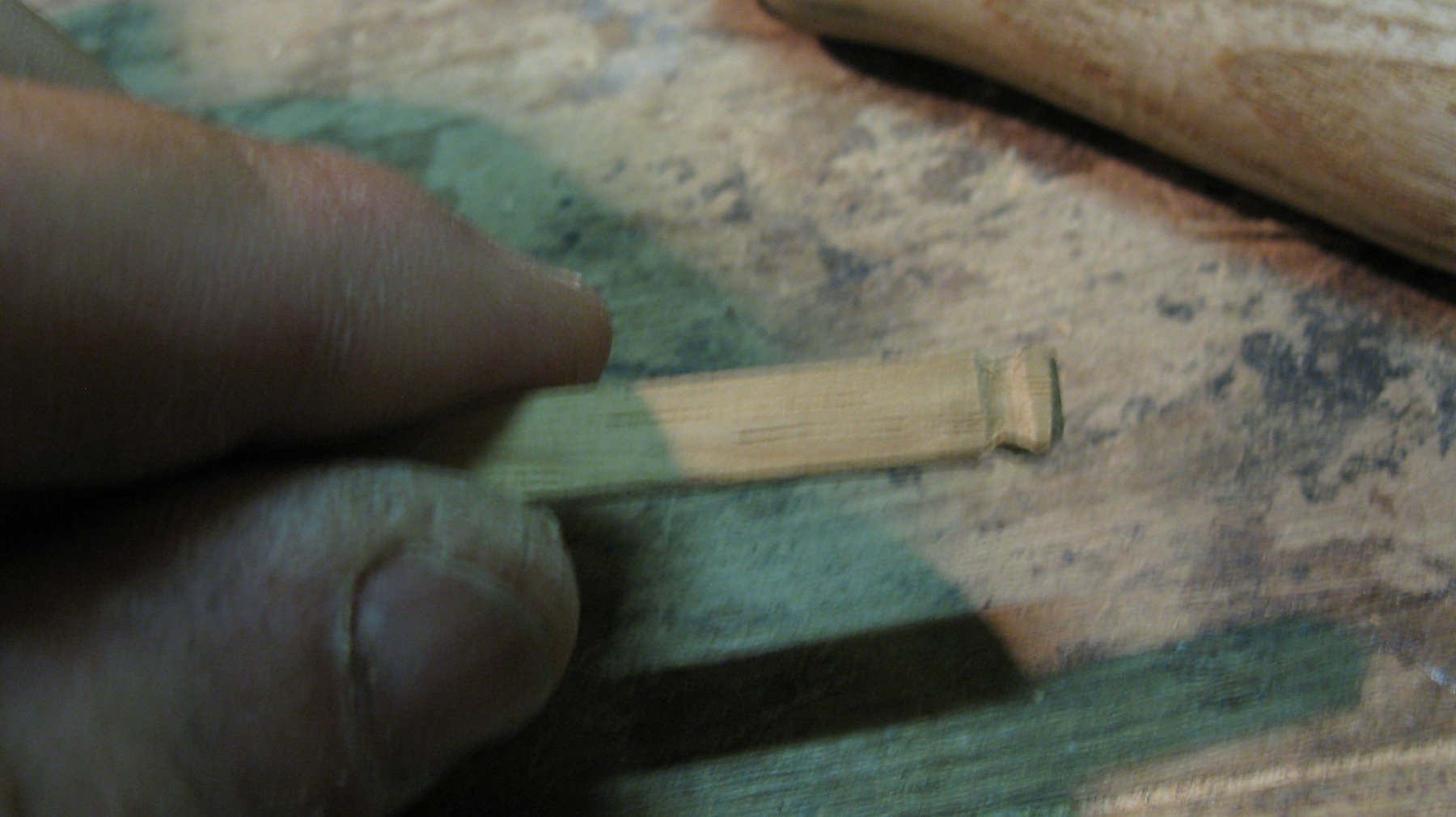
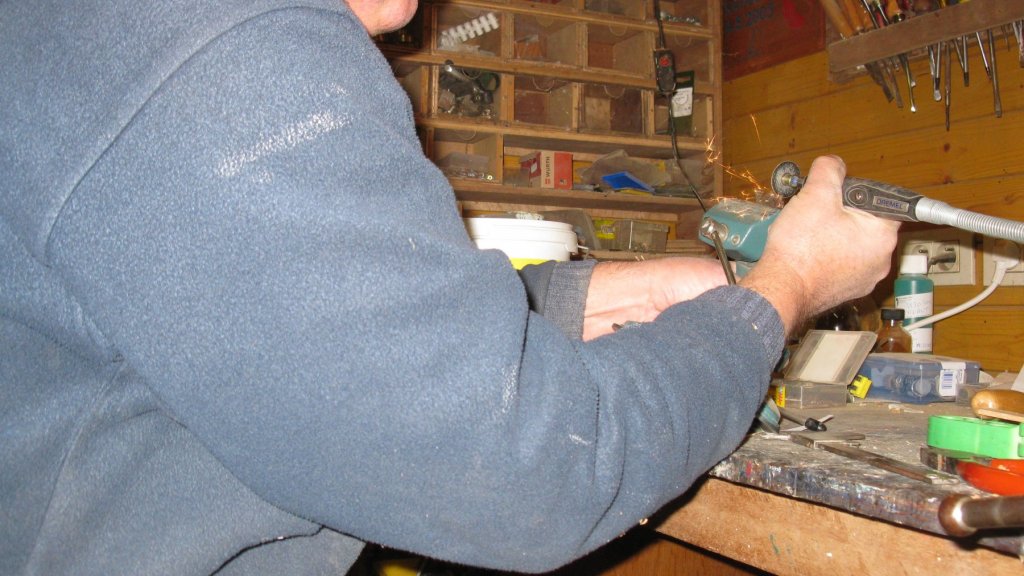
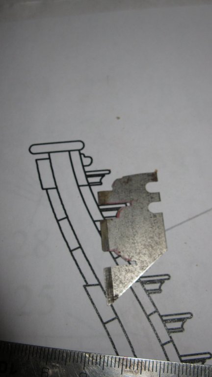
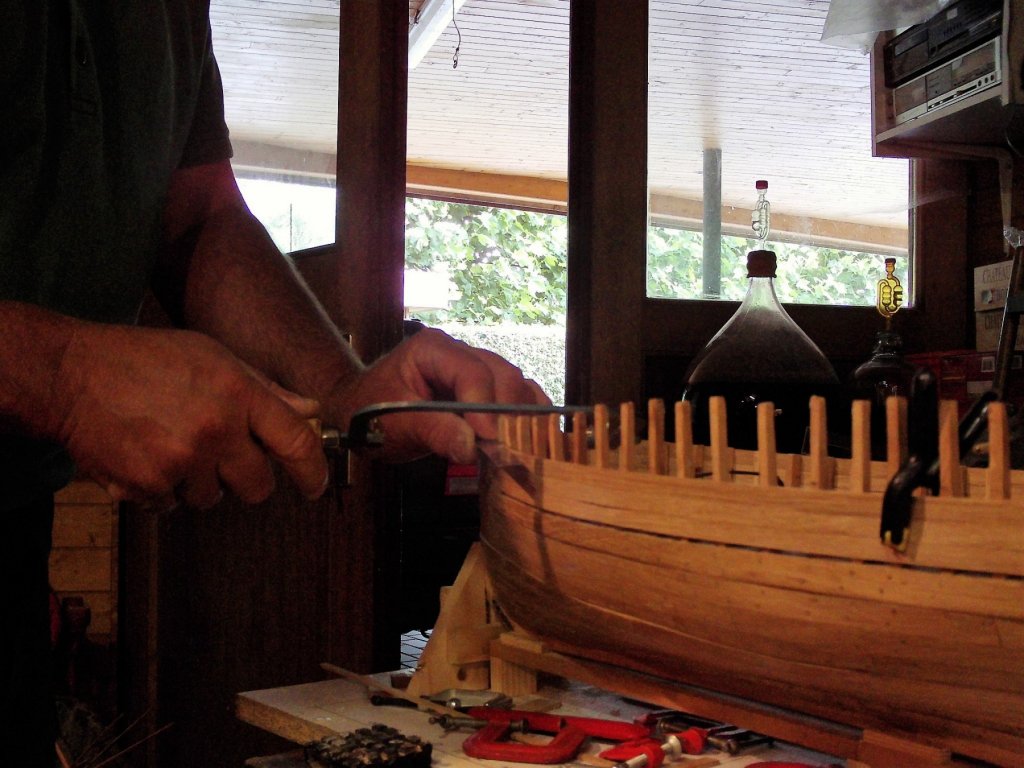
 Continuing the log: I make again a scraper to shape the entry steps.
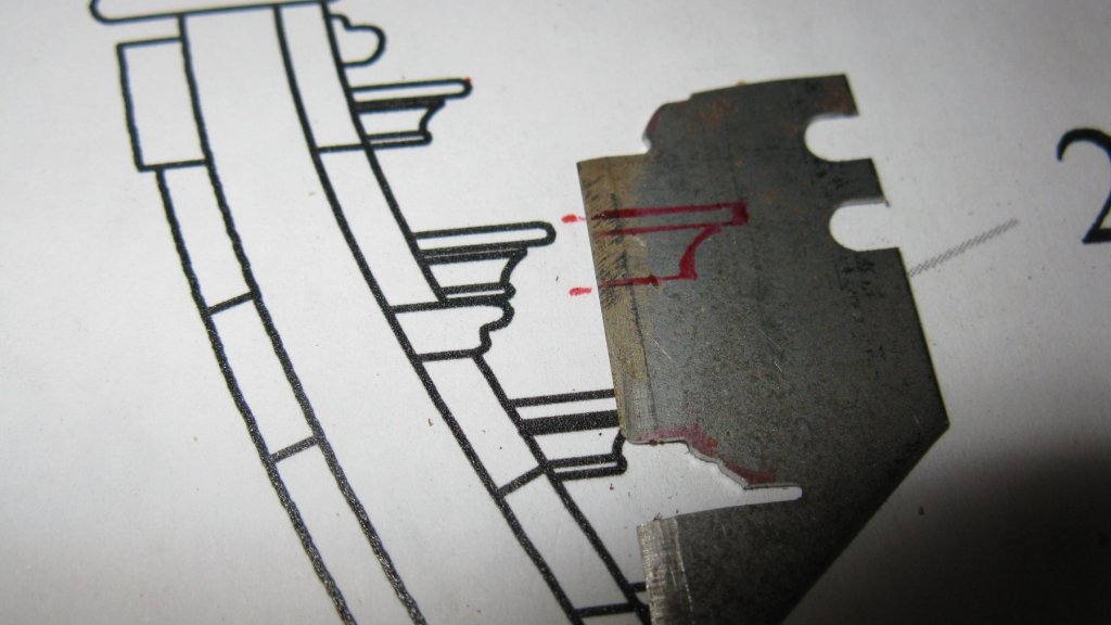
-
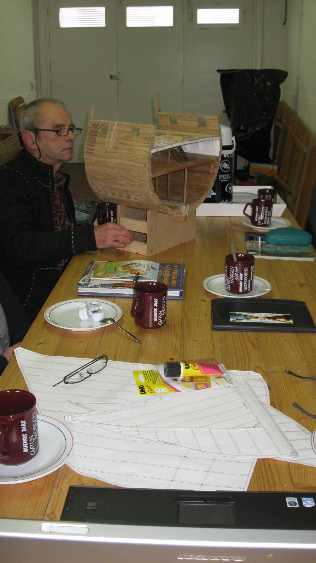
Thank you Christian. To give you an impression of the size: below a of one of my modelling friends examining my cross section during our monthly meeting yesterday afternoon. G.L.

-
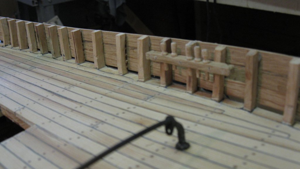
14.15 The port forward rail with belaying pins. The pins are made as described in my post 12.2.
-
14.14 Gluing the rails in place.

-
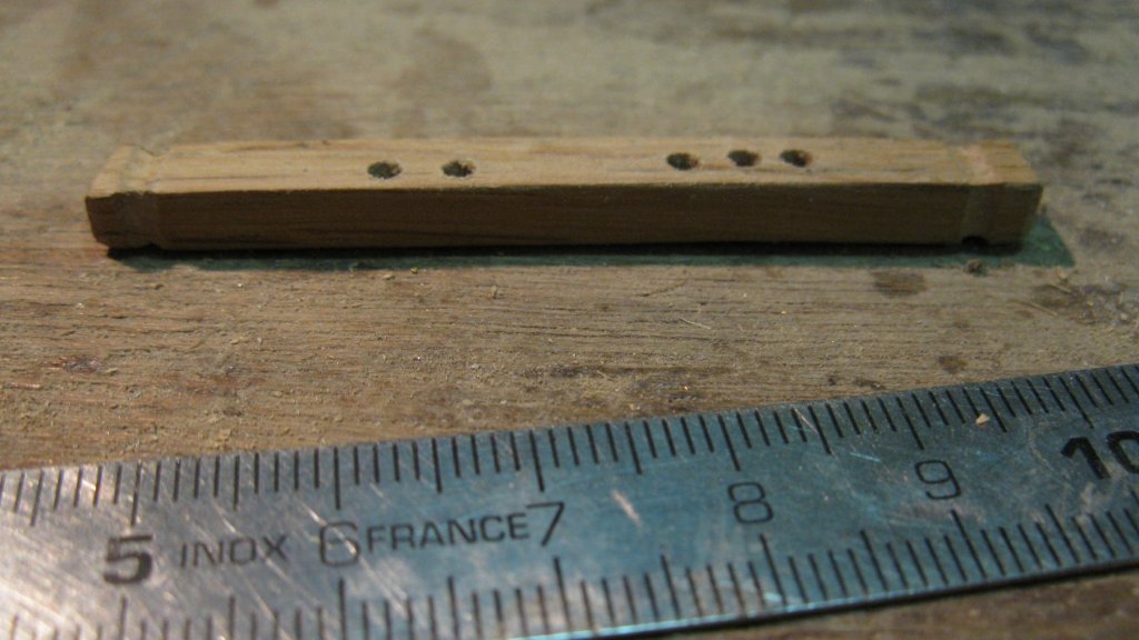
14.13 The forward rails have five holes for belaying pins, the aft three.
-
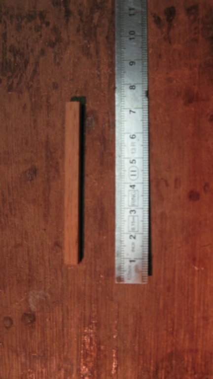
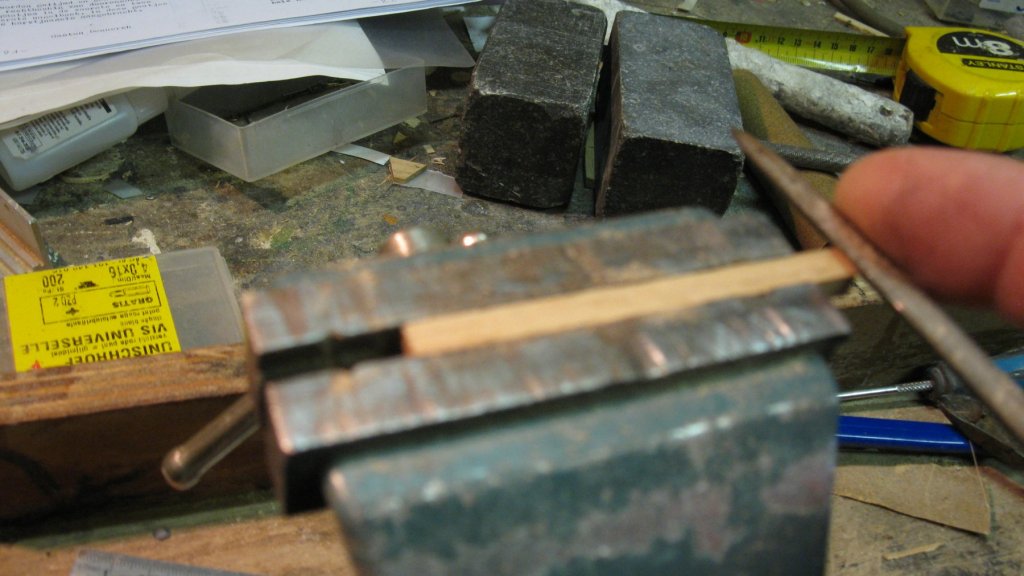
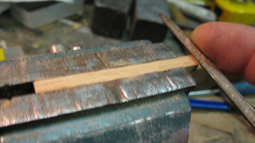
14.12 There are also four rails for belaying pins on the sides. The shaping of them is done in the same way as the bollards.

-
Excellent work, Patrick. The Triple is really earned! G.L.
- 756 replies
-
- 3
-

-
- galleon
- golden hind
- (and 2 more)
-
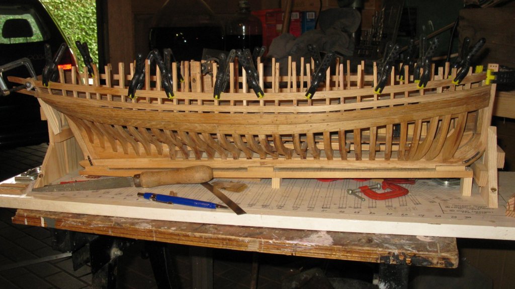
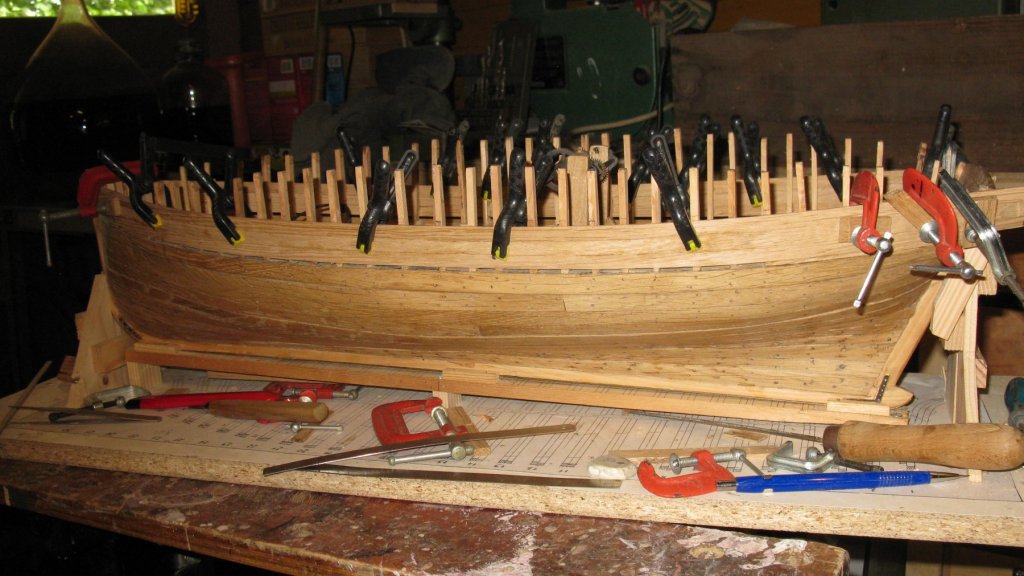
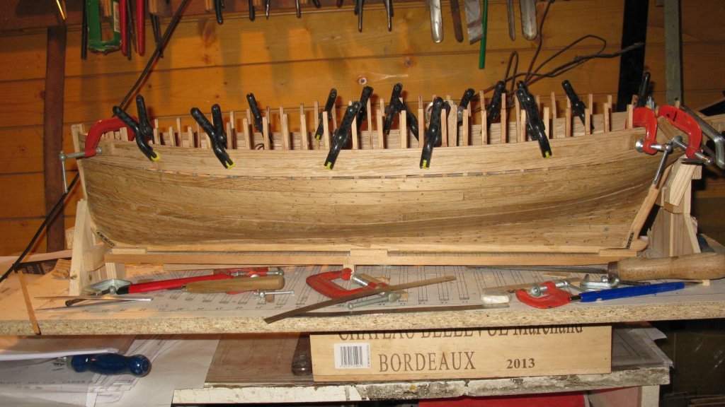
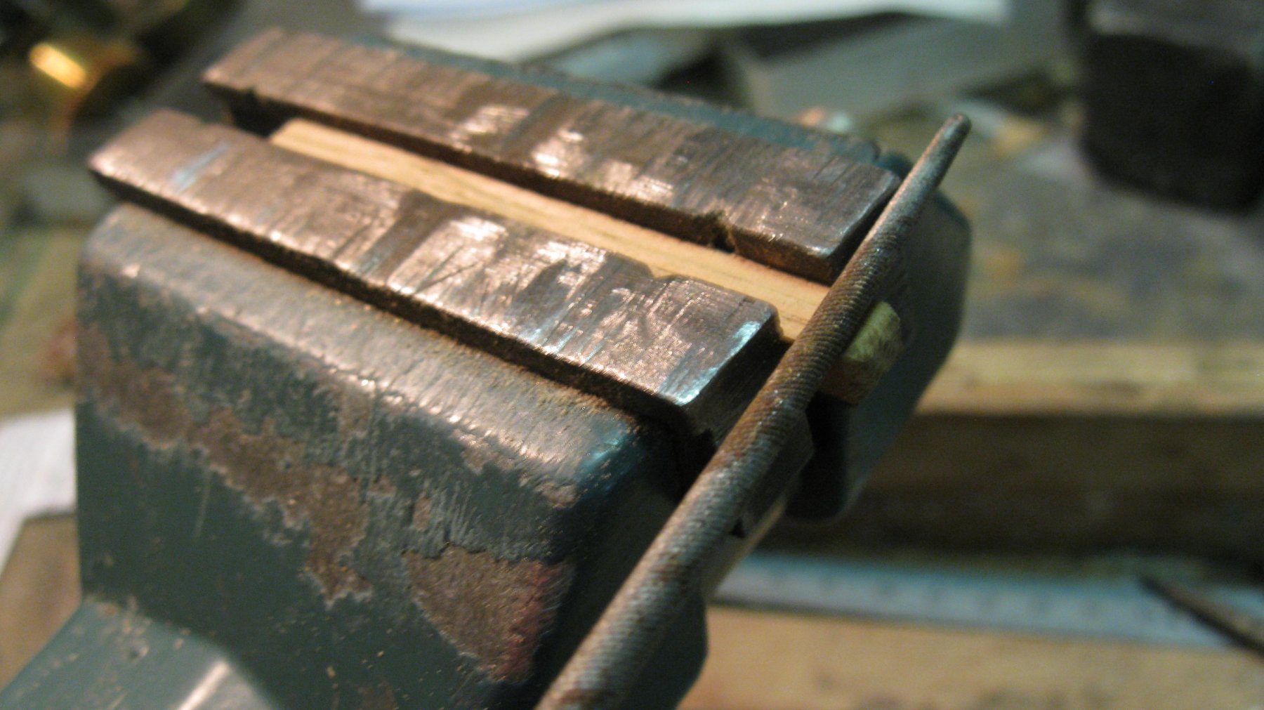
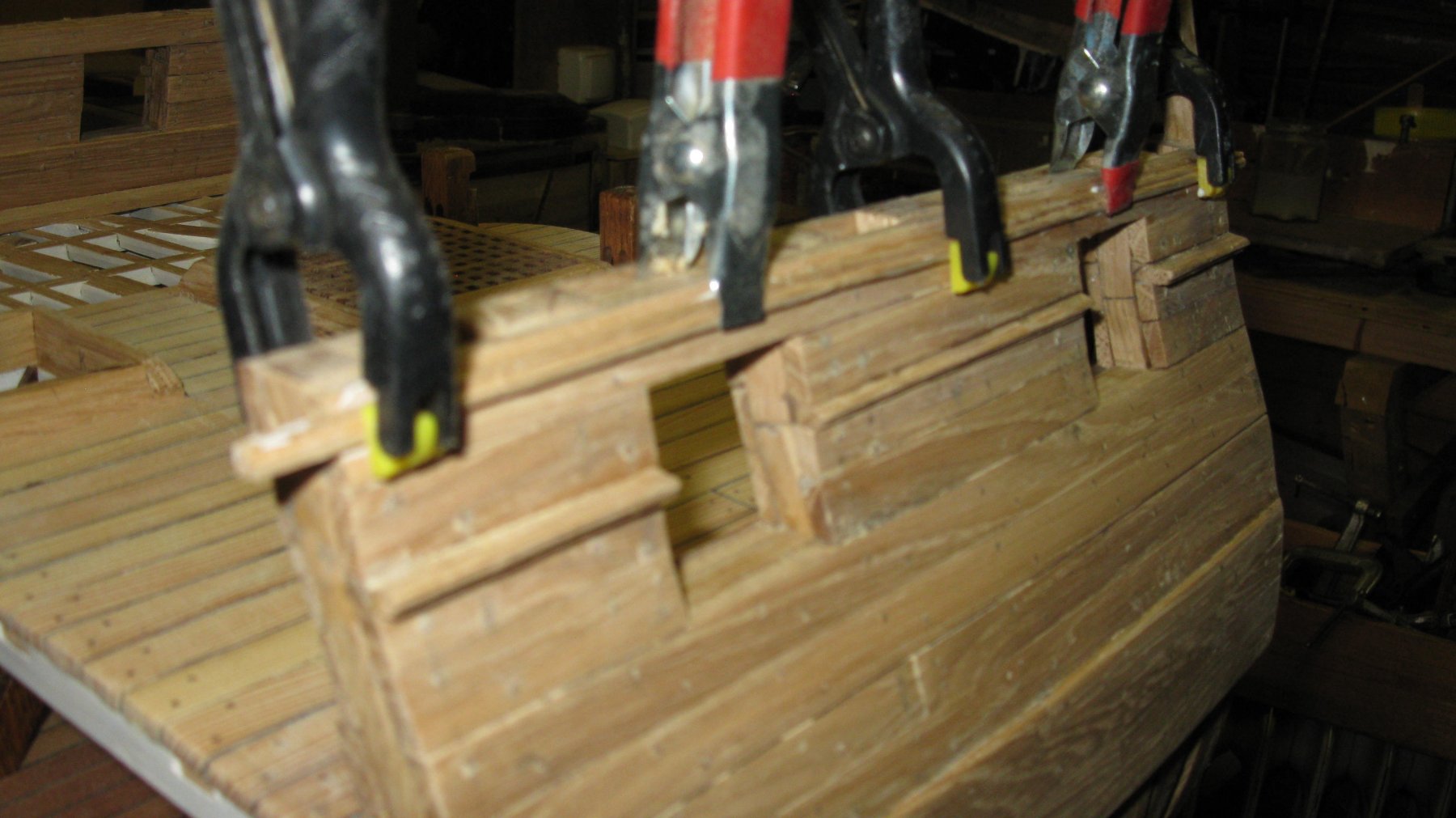
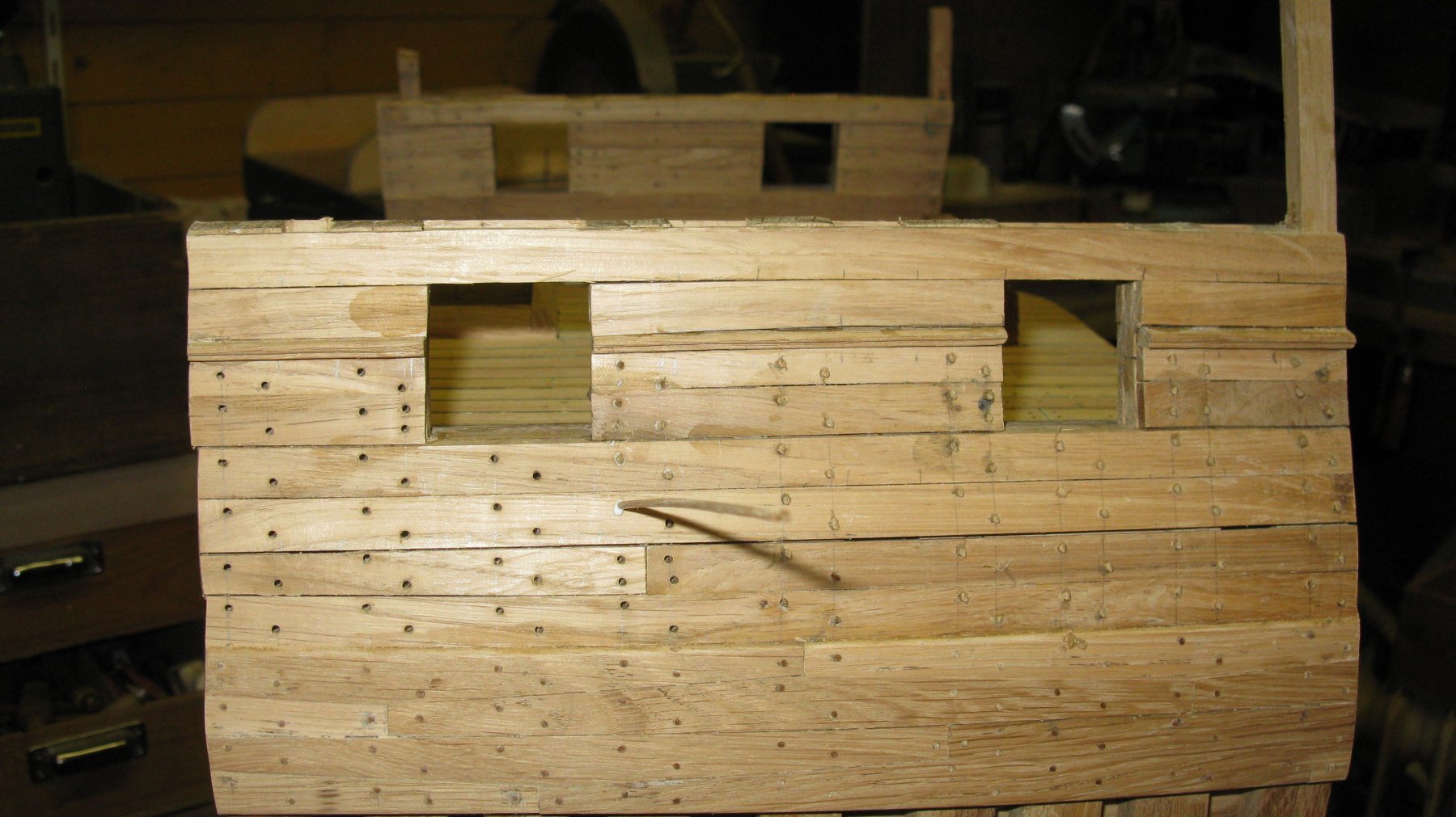
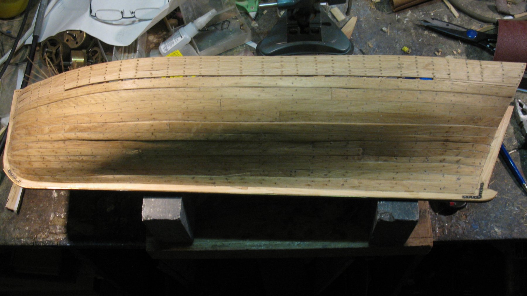
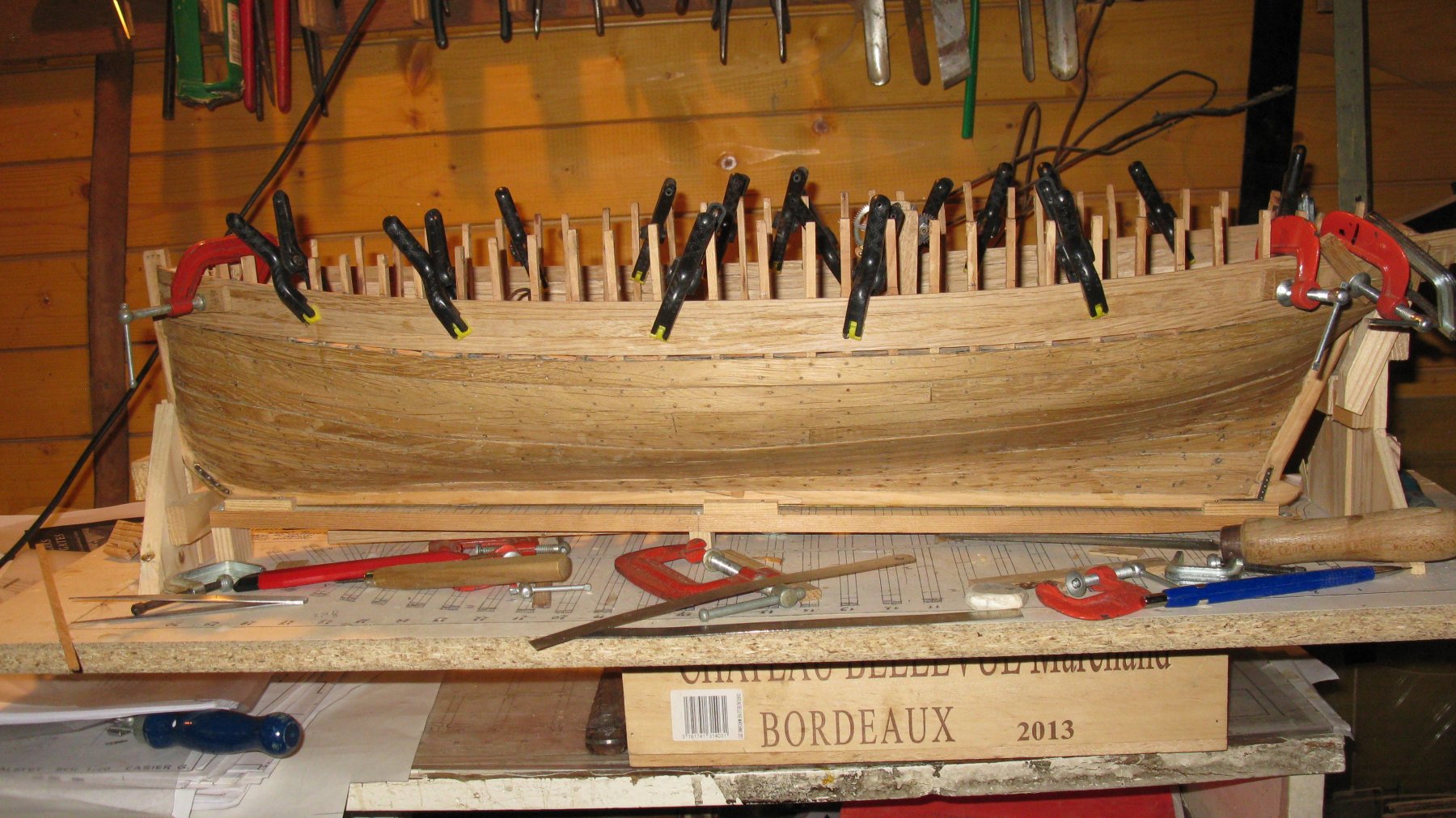
For the upper layer of outboard trims I use the same profile, but this time upside down. This time the trims are glued directly on the outboard planking.


-
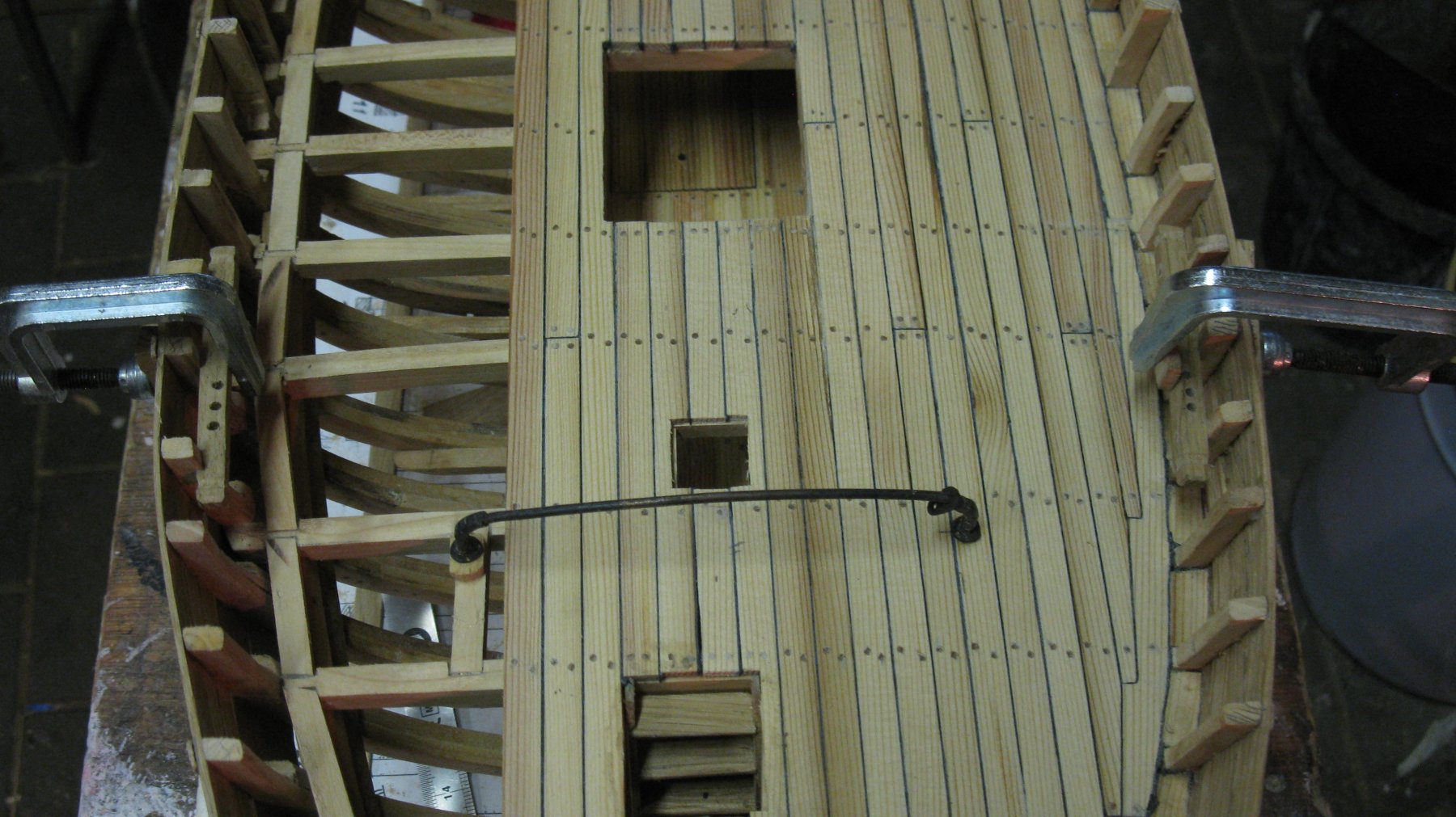
Then it is again further planking upwards, tree nailing and sanding.


-
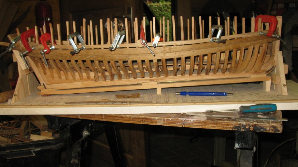
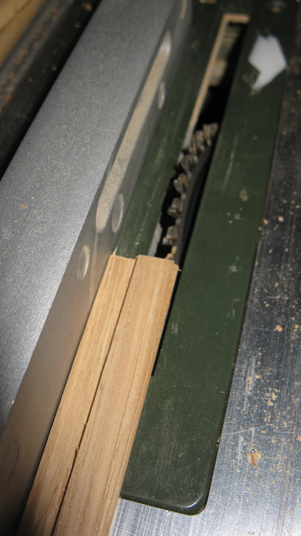
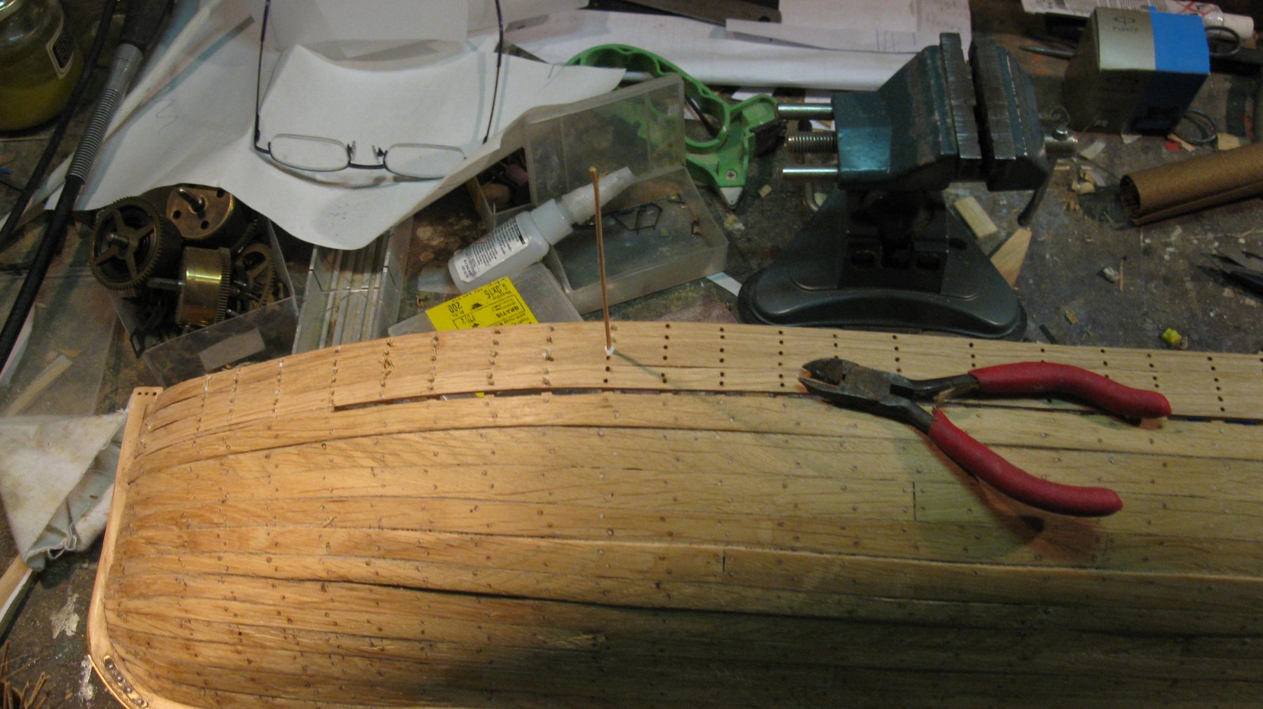
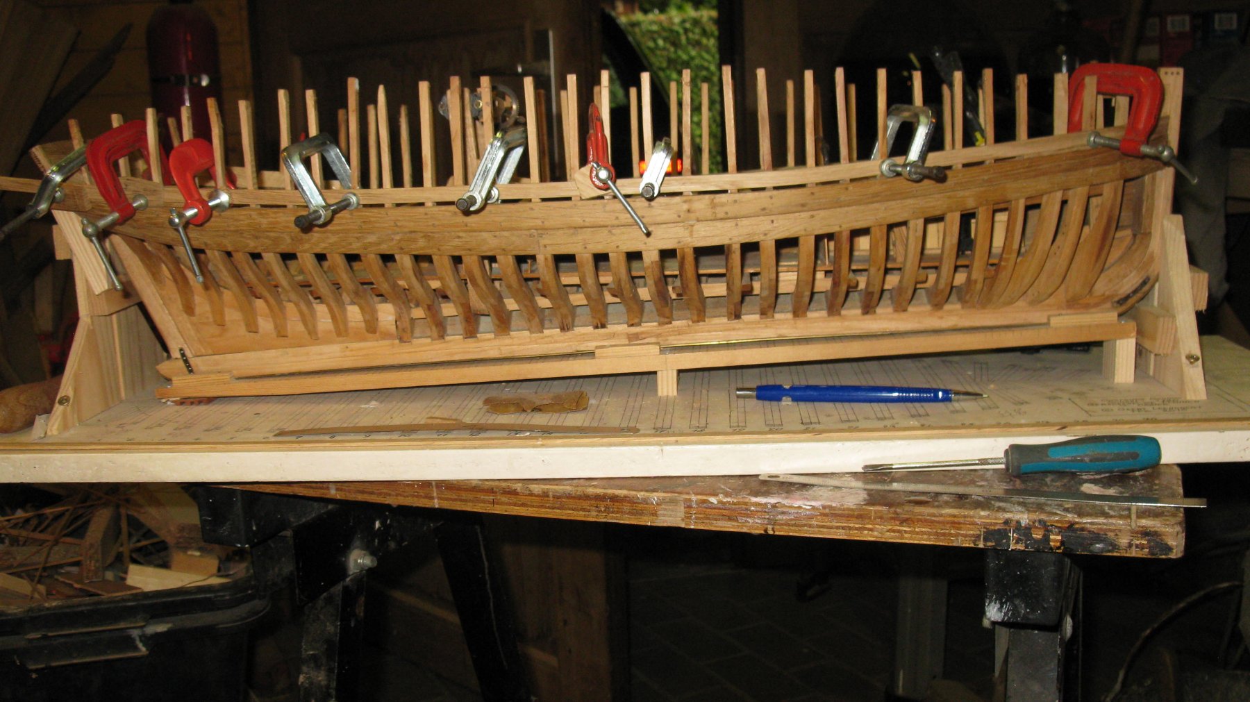
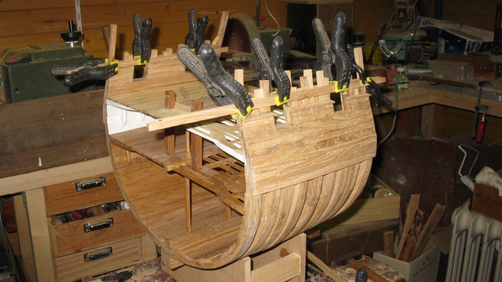
Some small nails in pre drilled holes keep the trims on their place when the glue is drying. As You can also see I glued little pieces of wood to lengthen the frames which were a bit too short.
-
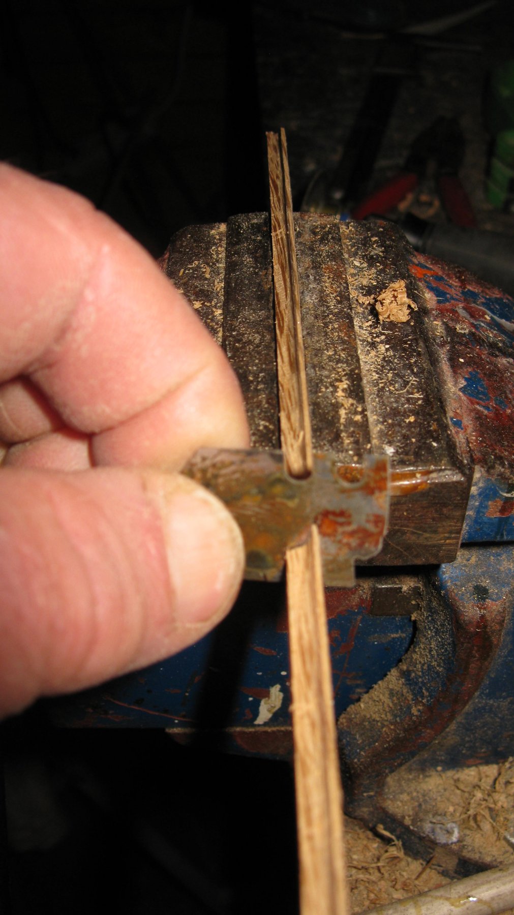
I saw the back side of them to the correct angle with the help of the adjustable table saw.

-
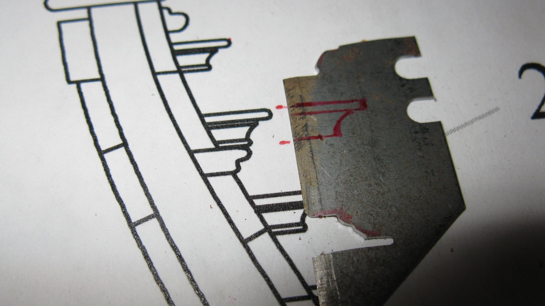
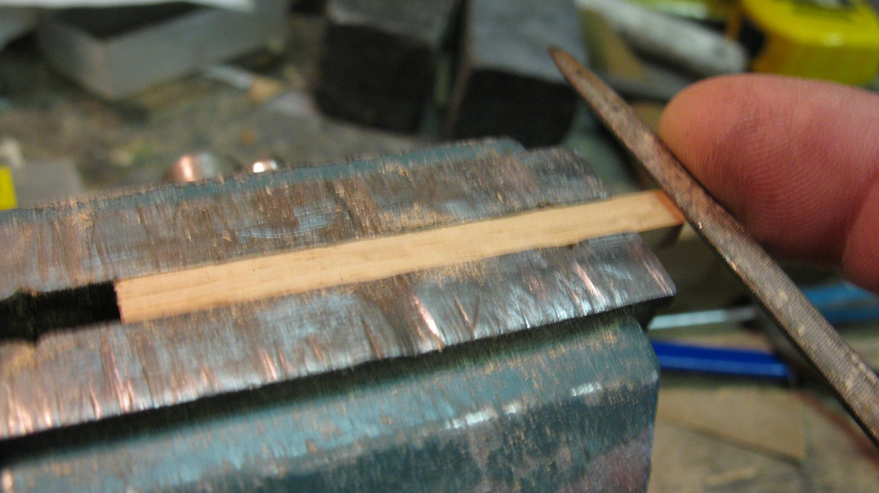
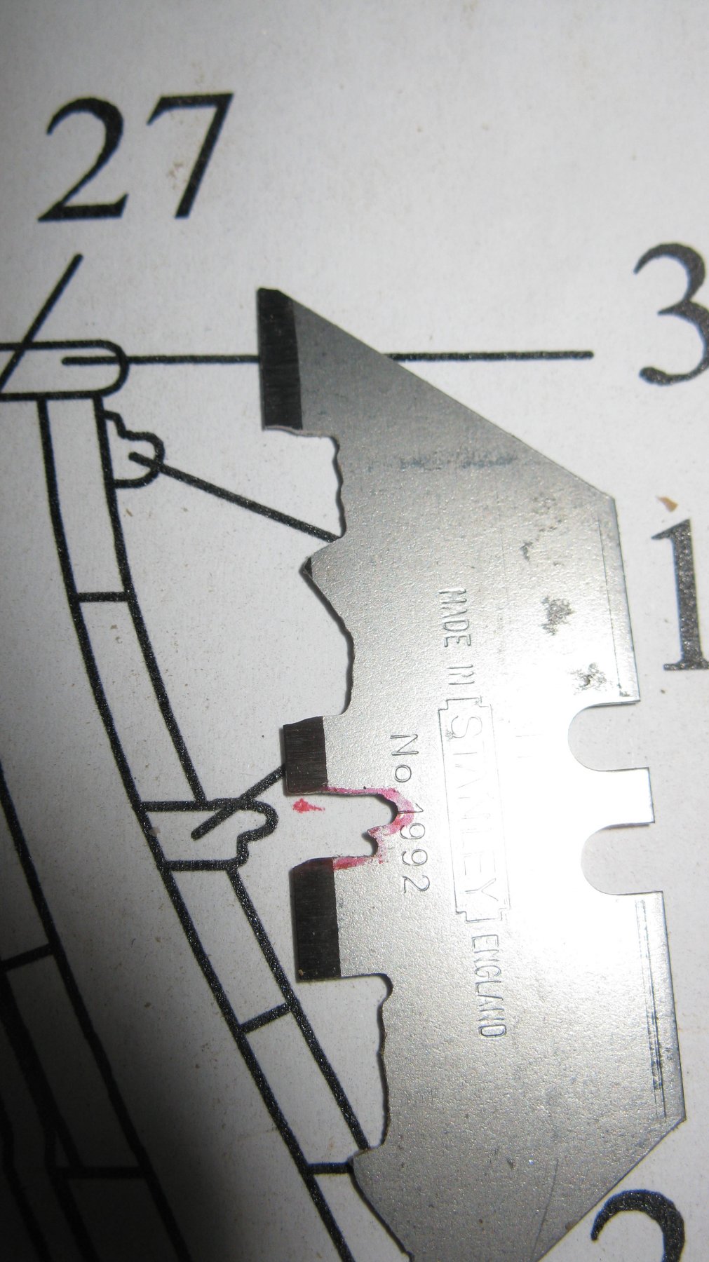
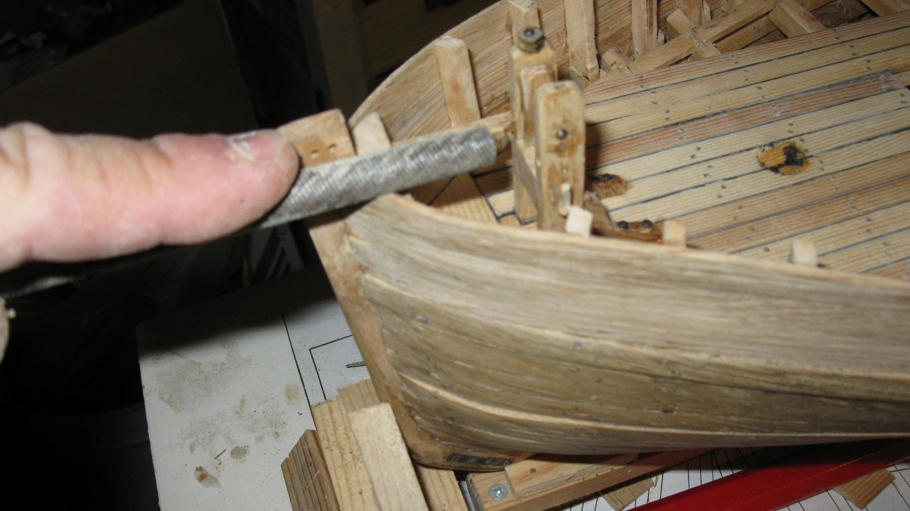
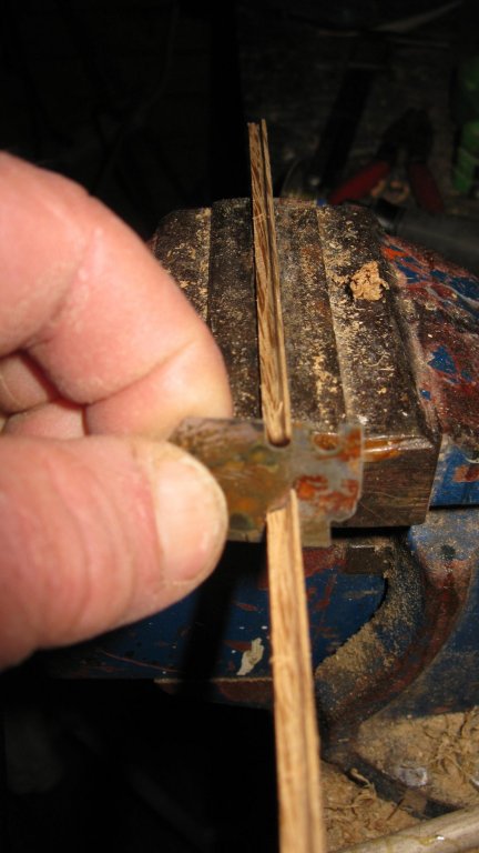
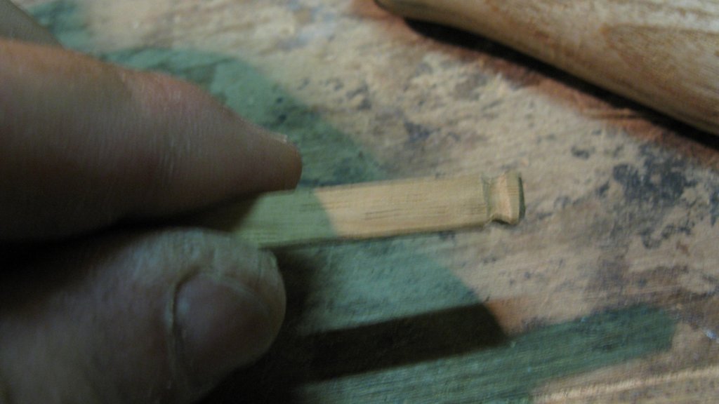
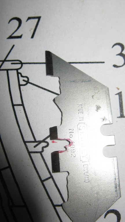
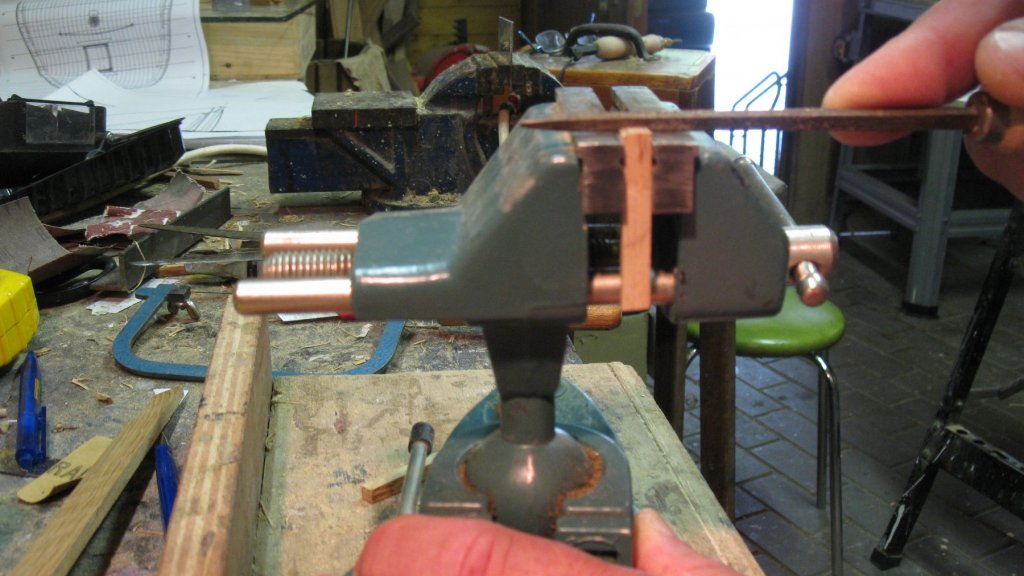
To make the outboard trims, I make a scraper with a piece of a cutter knife.
-
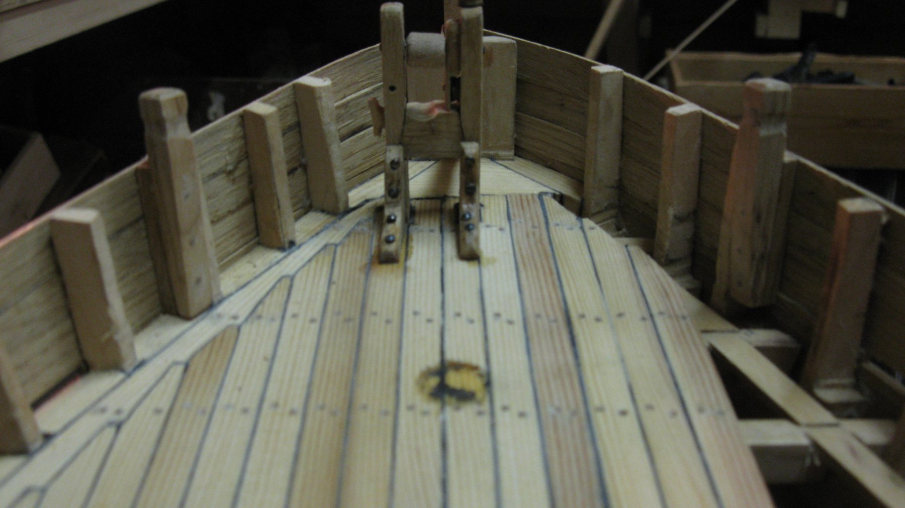
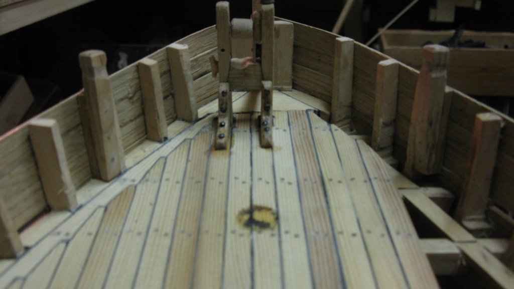
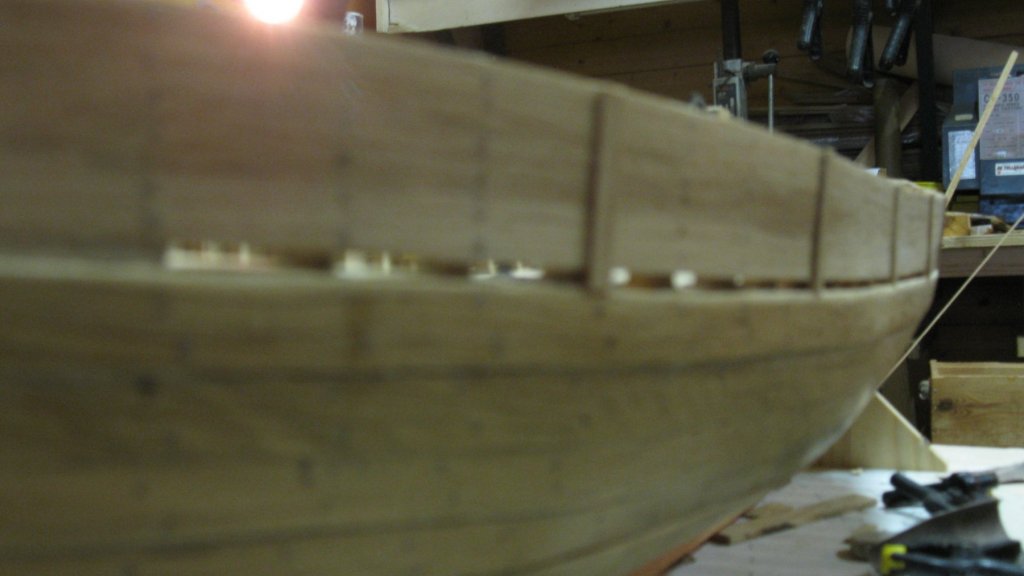
14.11 The forward bollards
-
14.10 A bollard glued into its place.

-
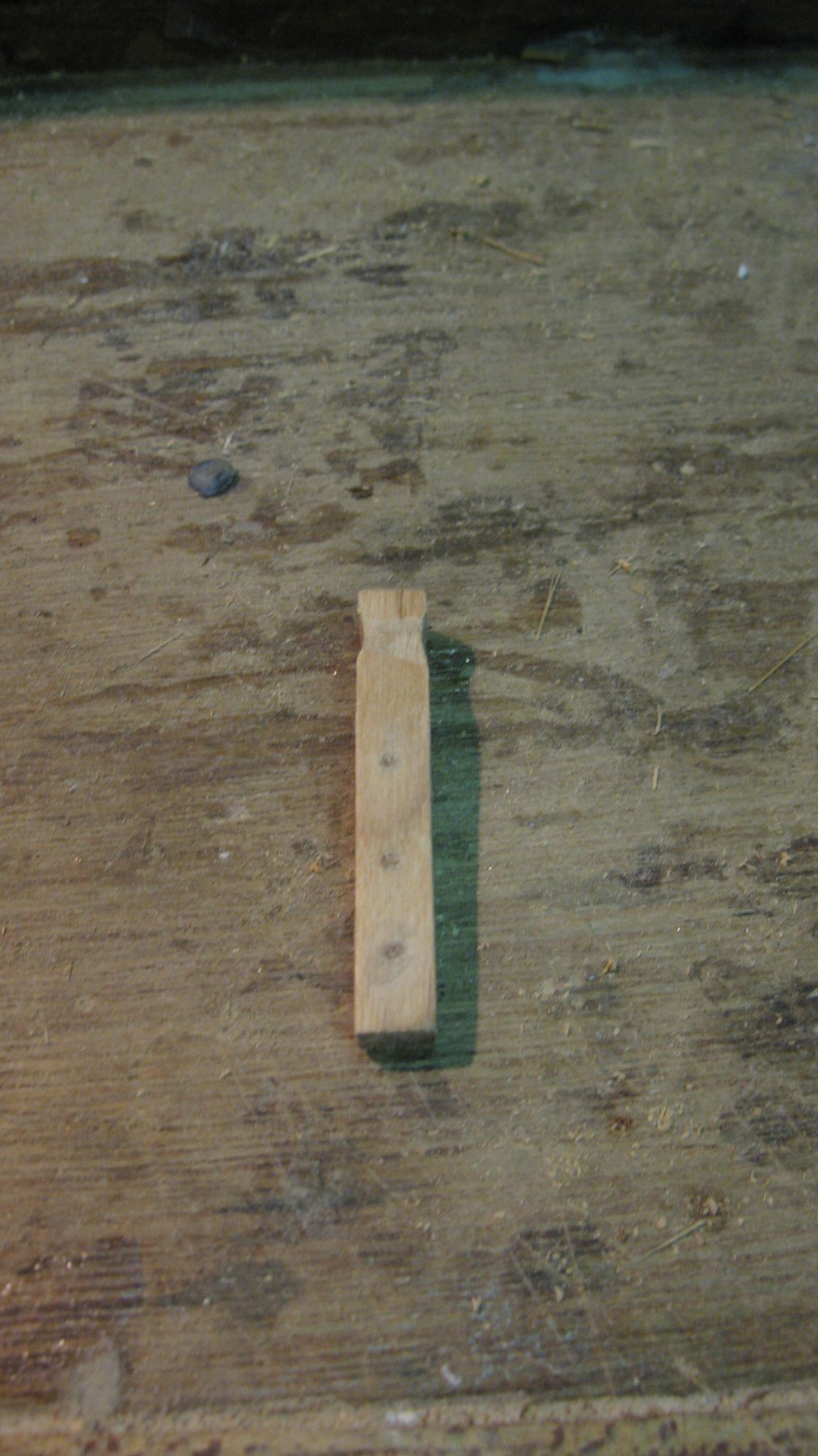
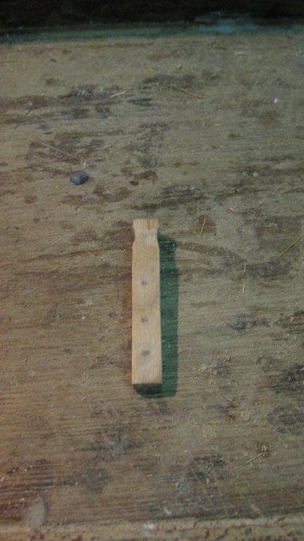
14.9 The finished bollard.
-
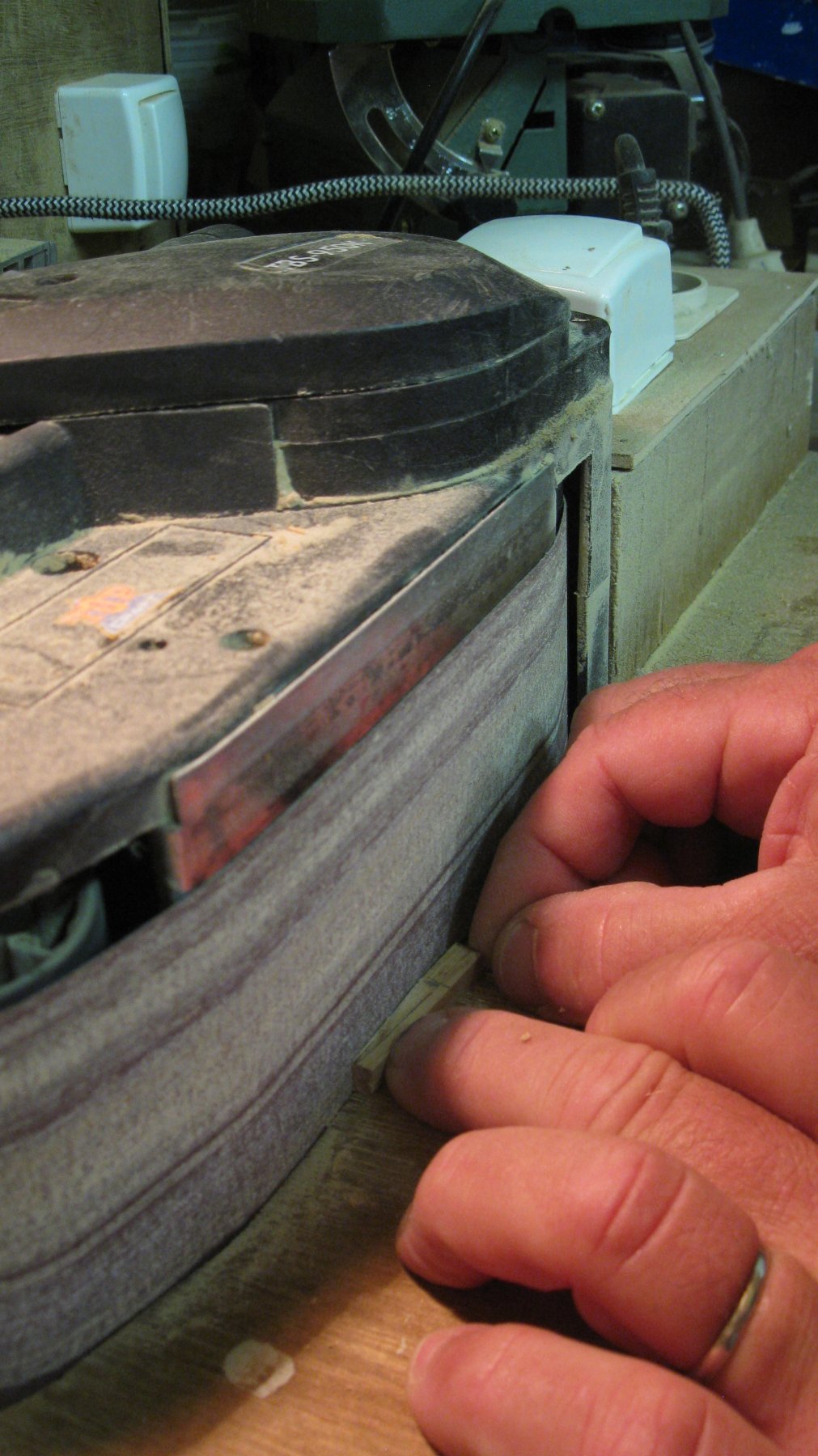
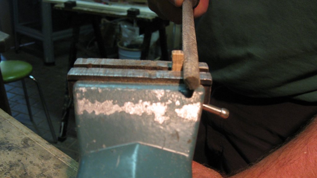
14.9 The top of the bollard is filed in shape with triangular and round files.
-
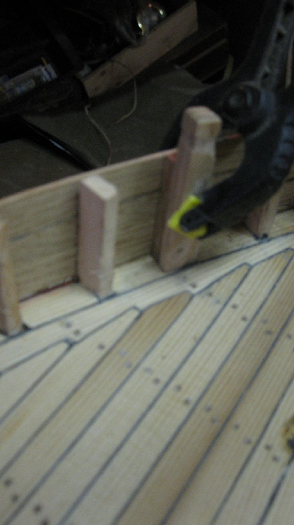
14.8 One side is sanded oblique to fit against the stanchion.

-
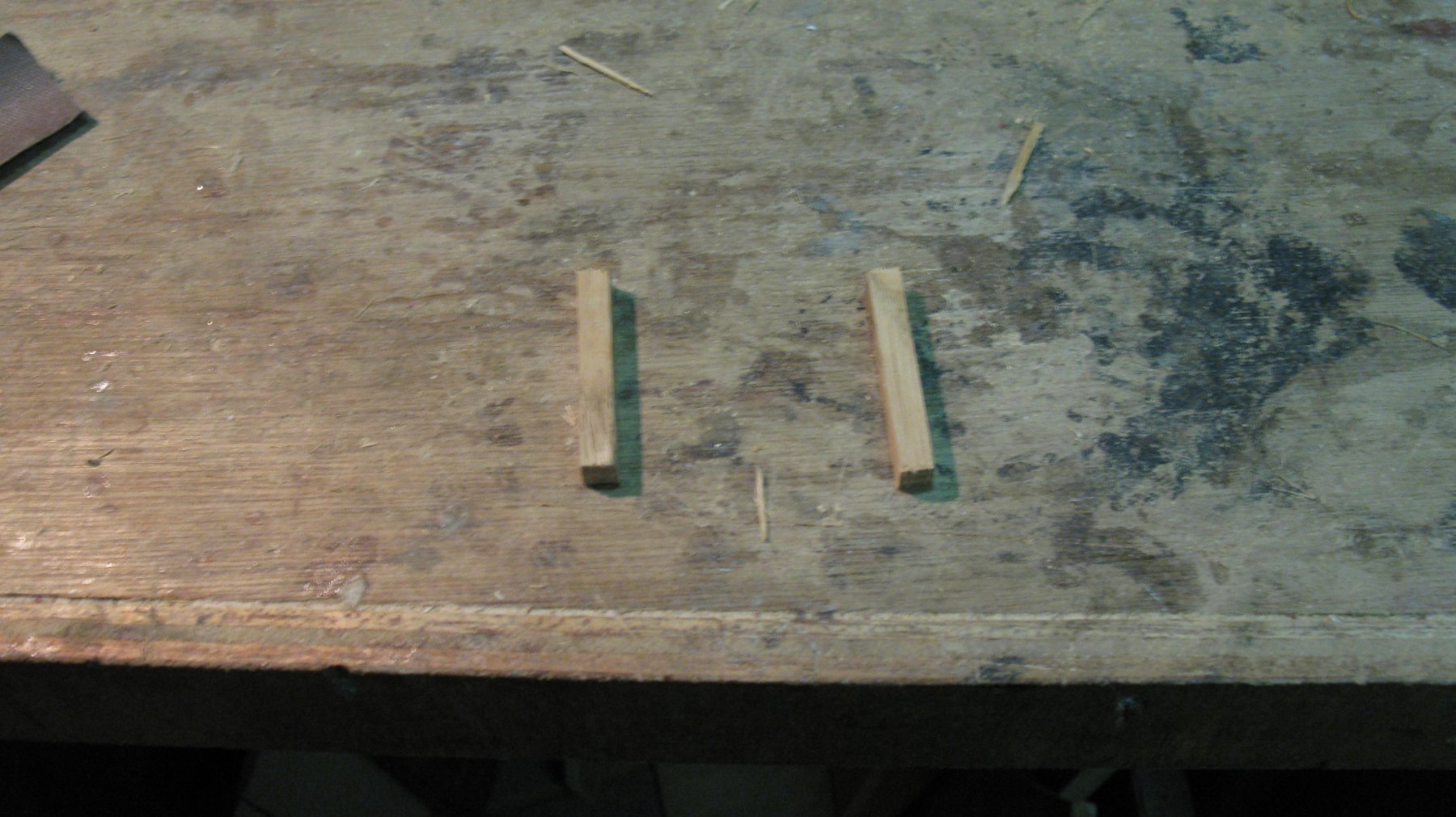
14.7 There are four bollards on the deck, two forward and two aft. I make them of small oak bars.
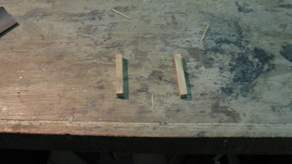
-
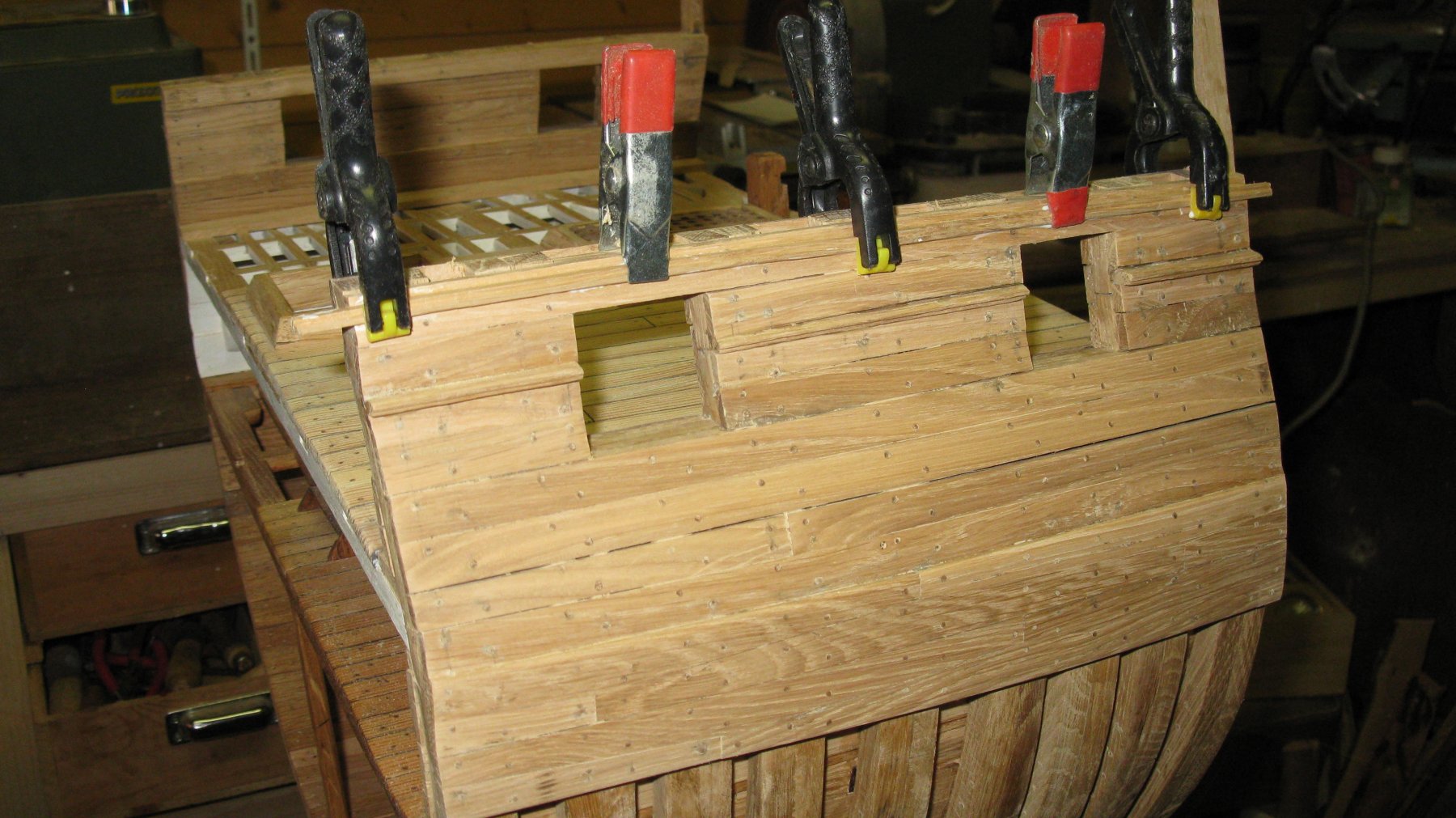
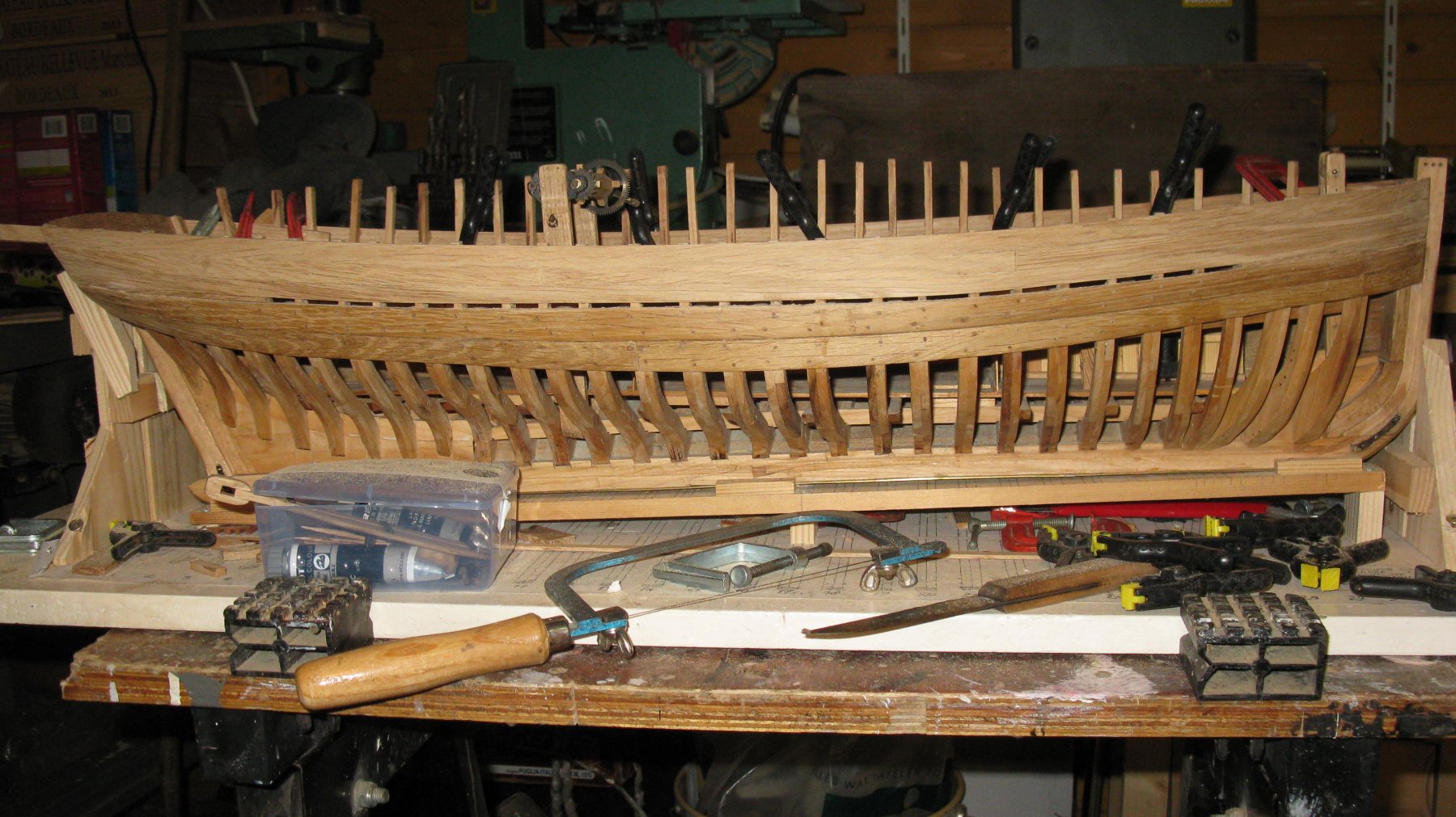
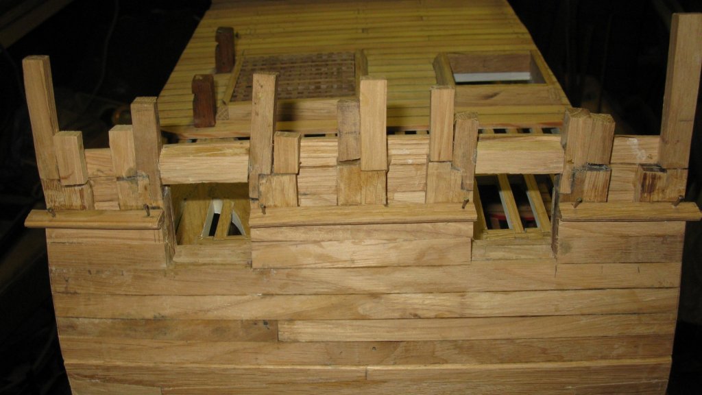
Here they come, Patrick. 14.6 The bulwark is at the outside strengthened with seven vertical planks on each side.
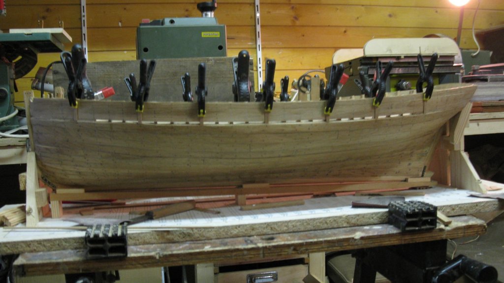
-
This is the point where I lost my log in December! From here on we will continue the building log with new posts.

-
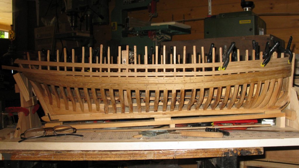
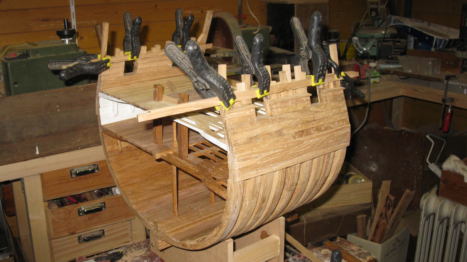
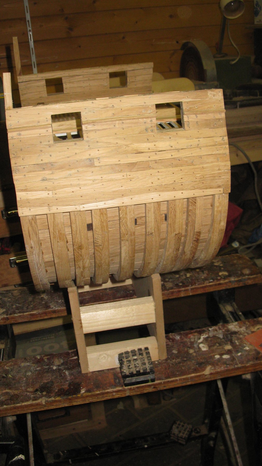
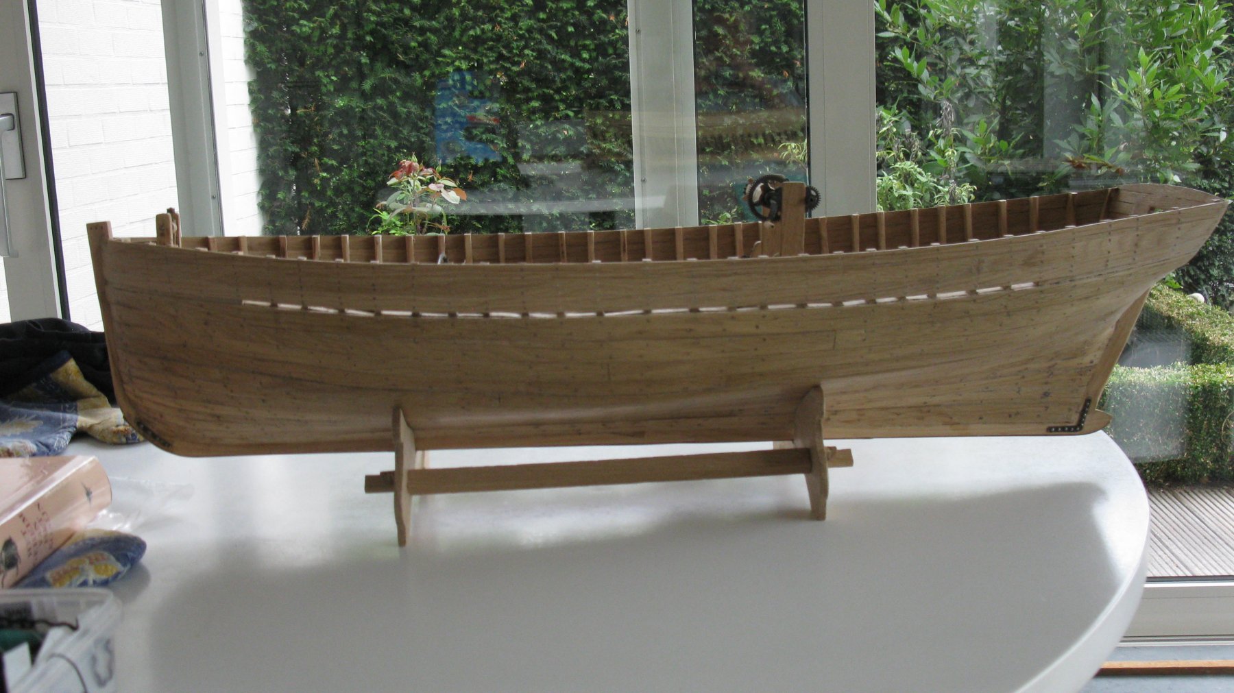
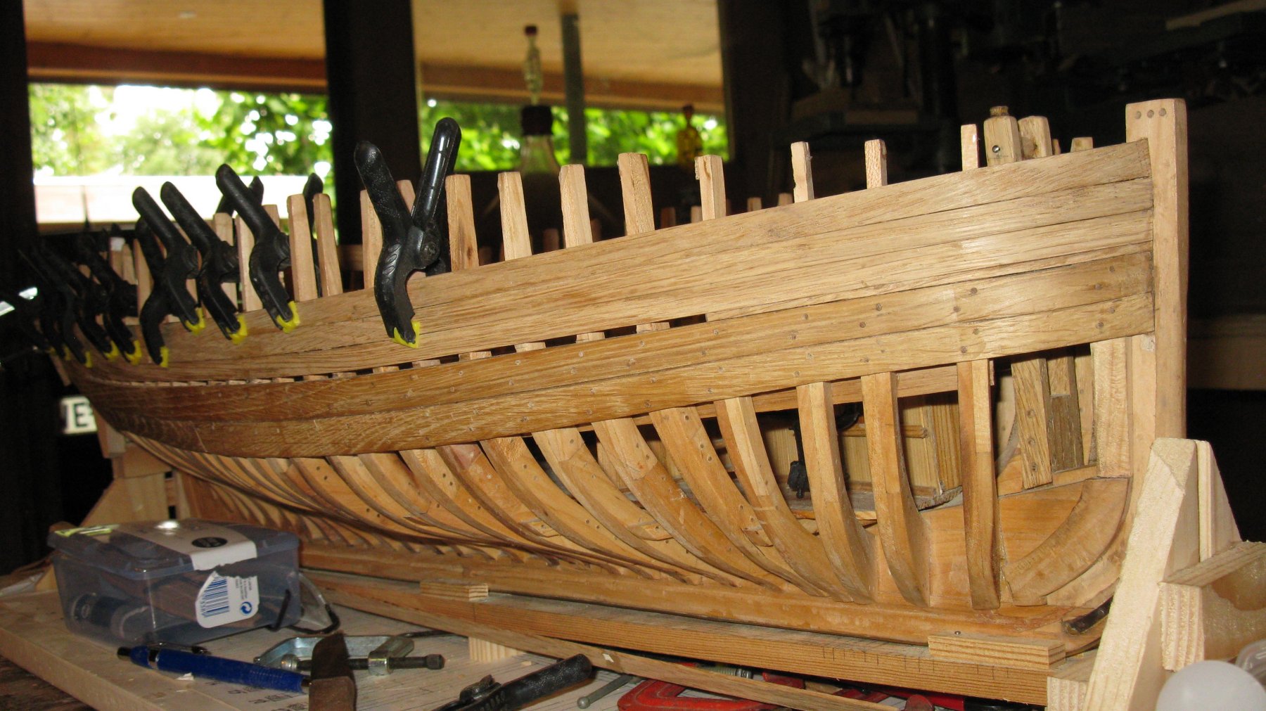
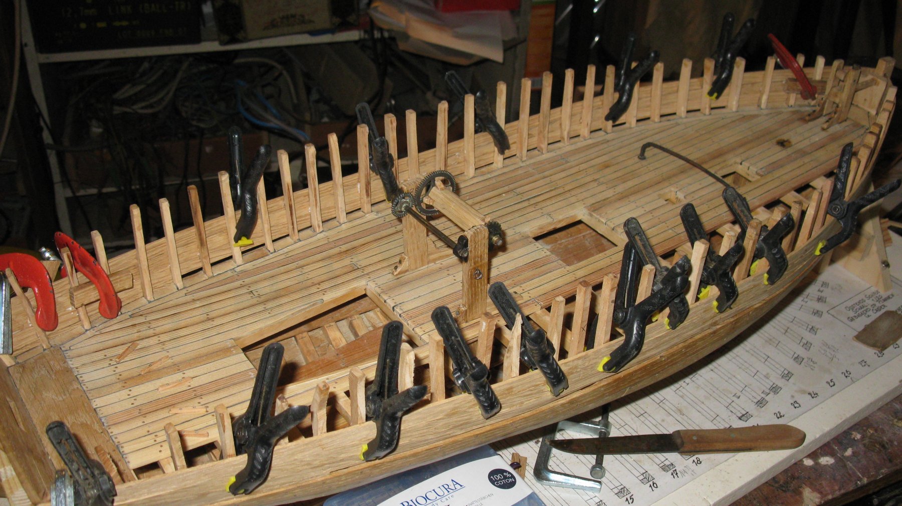
14.5 It looks already a lot more like the boat I want to build!
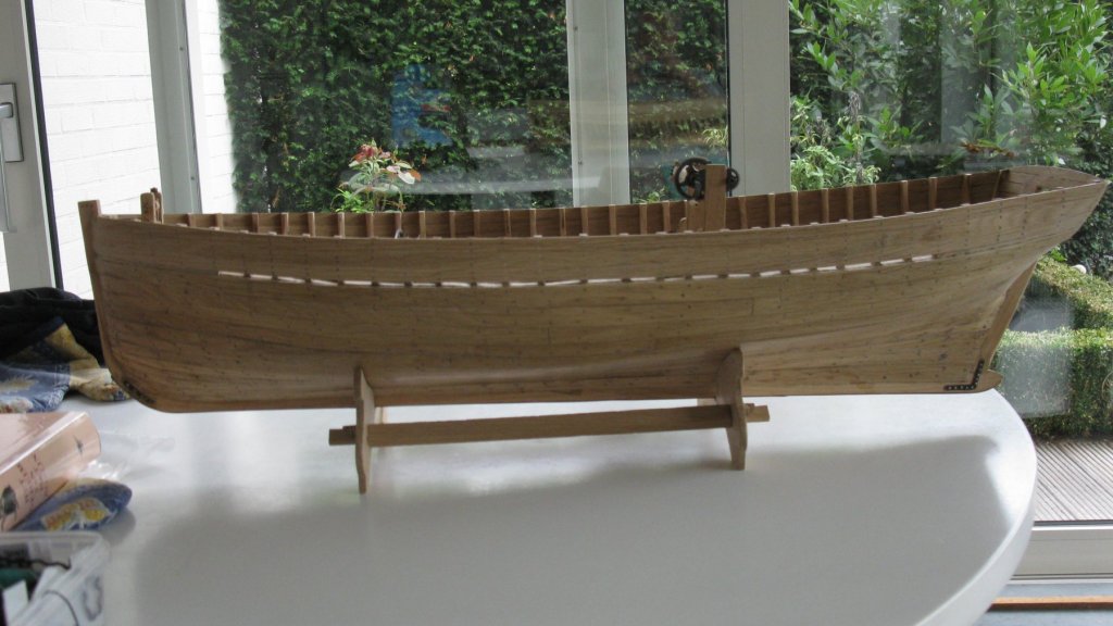
-
14.4 The job is finished off by tree nailing the bulwark.


-
14.3 The slot for the jib boom is filed out with a round file.


-
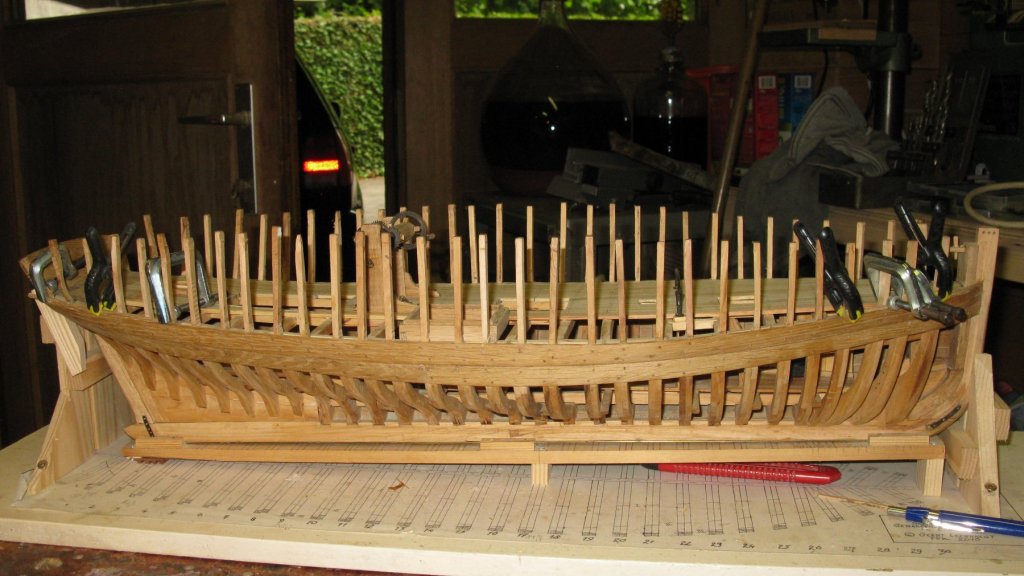
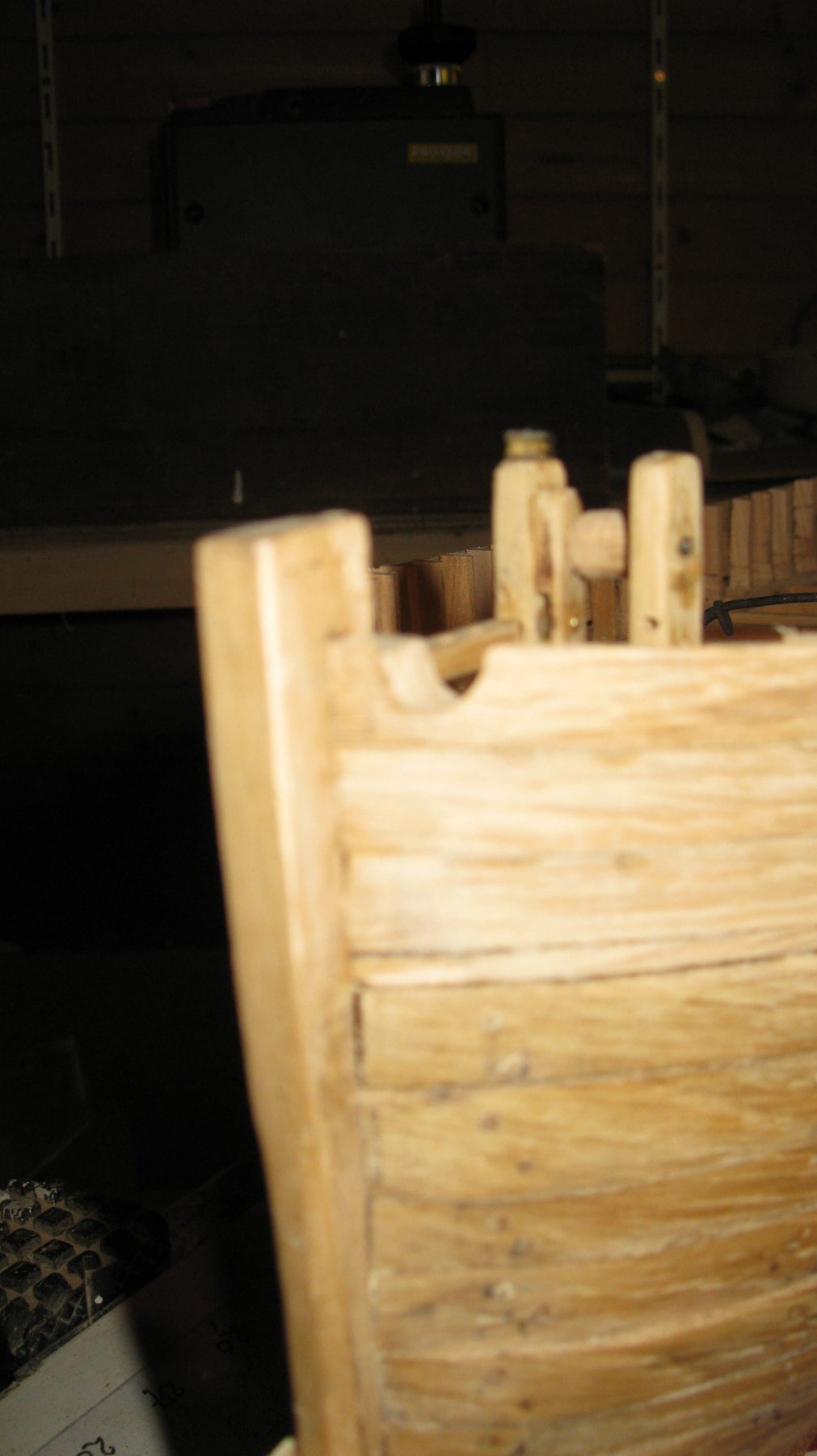
14.2 Now I can shorten the excesses of the frame futtocks. They are sawn so that the extend about a millimeter above the bulwark.
-
Part 14: Finishing the bulwark 14.1 Planking the bulwark.