G.L.
-
Posts
1,553 -
Joined
-
Last visited
Content Type
Profiles
Forums
Gallery
Events
Everything posted by G.L.
-
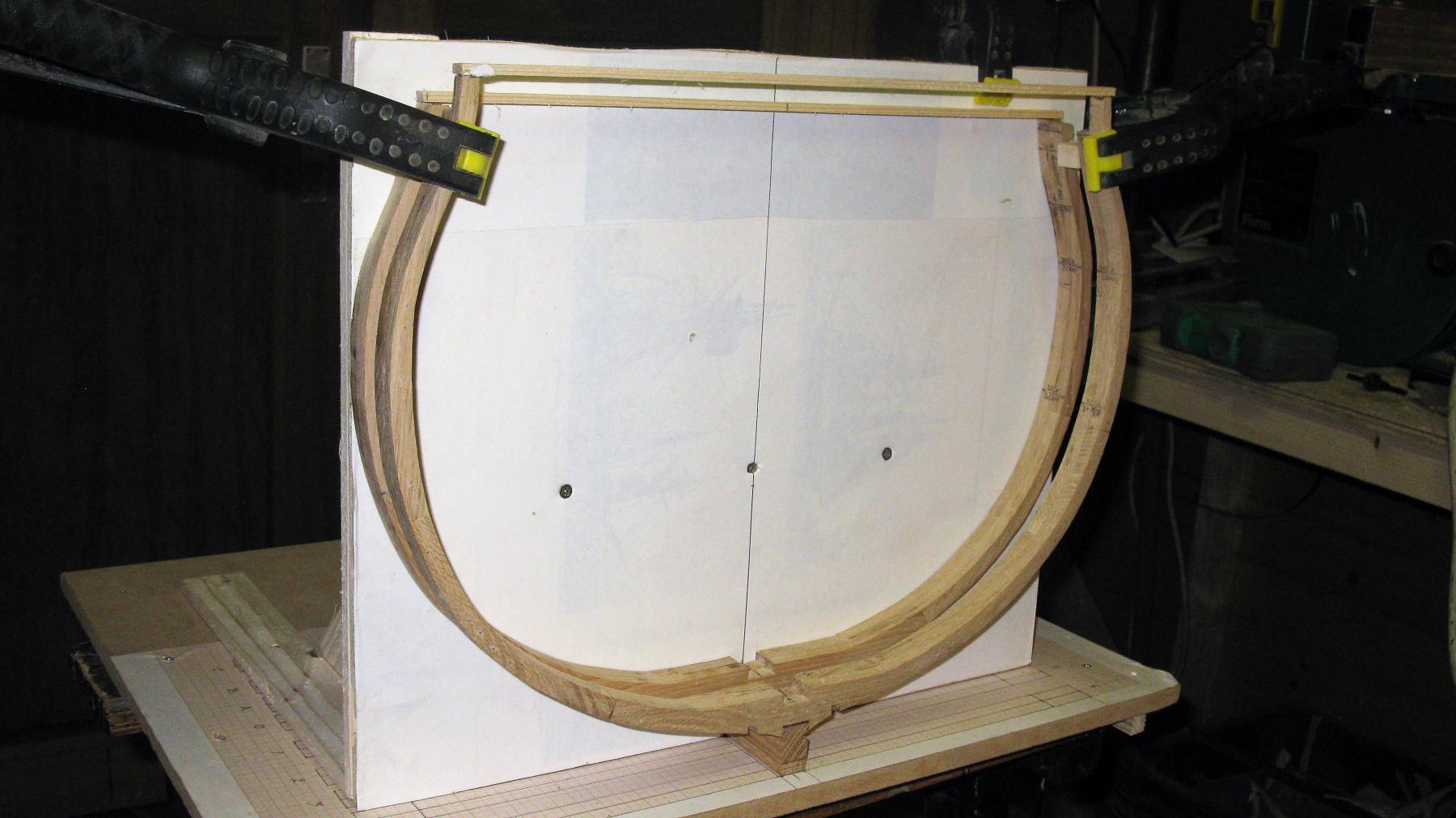
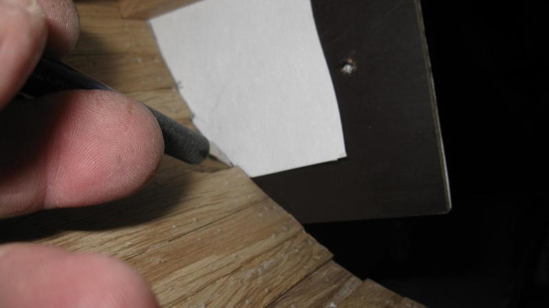
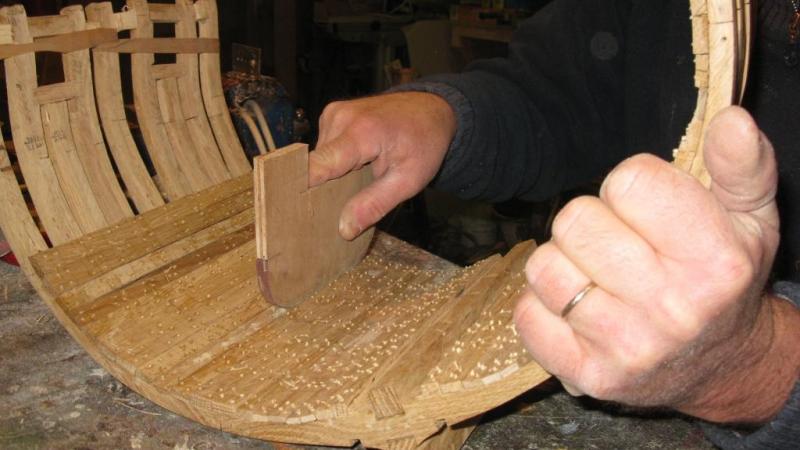
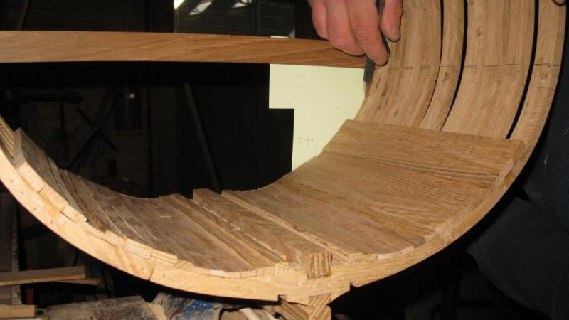
 I make now the hanging knees. First of all I attach a piece of drawing paper to the model to be able to copy the profile of the inner planks.
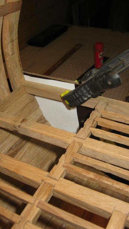
-
Tony, I am glad that my log is perking up your evenings. I am a interested follower of your cross section log and have learned a lot after you.
-
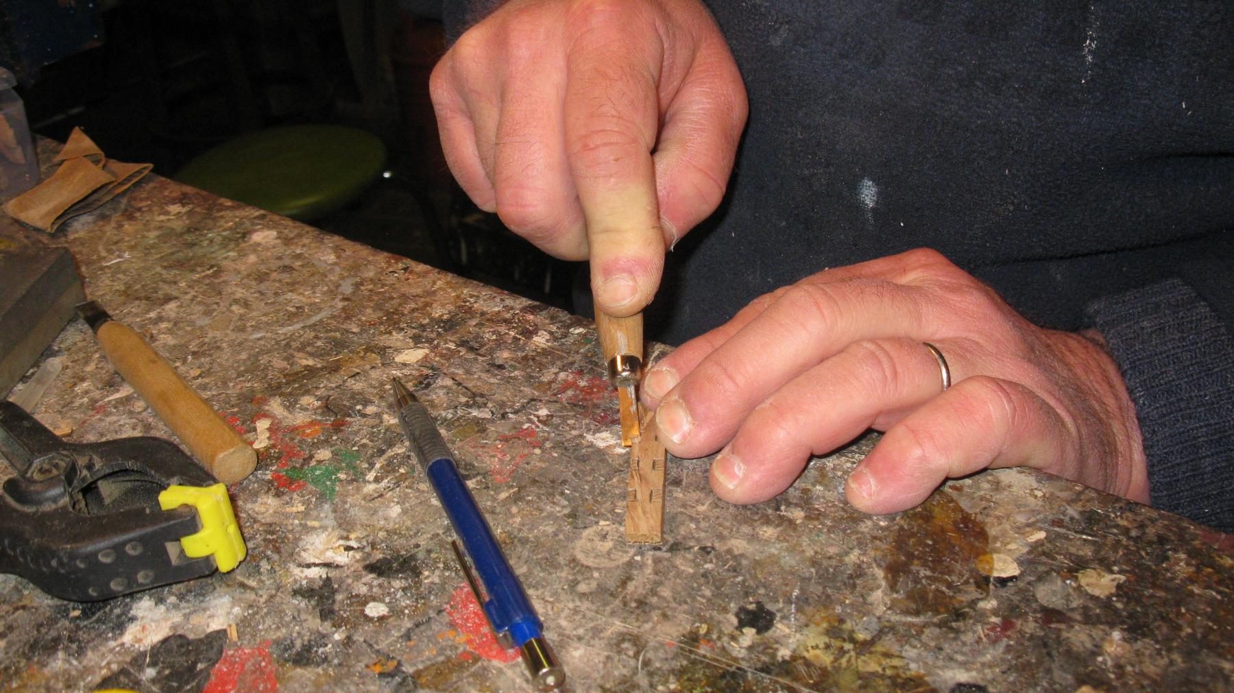
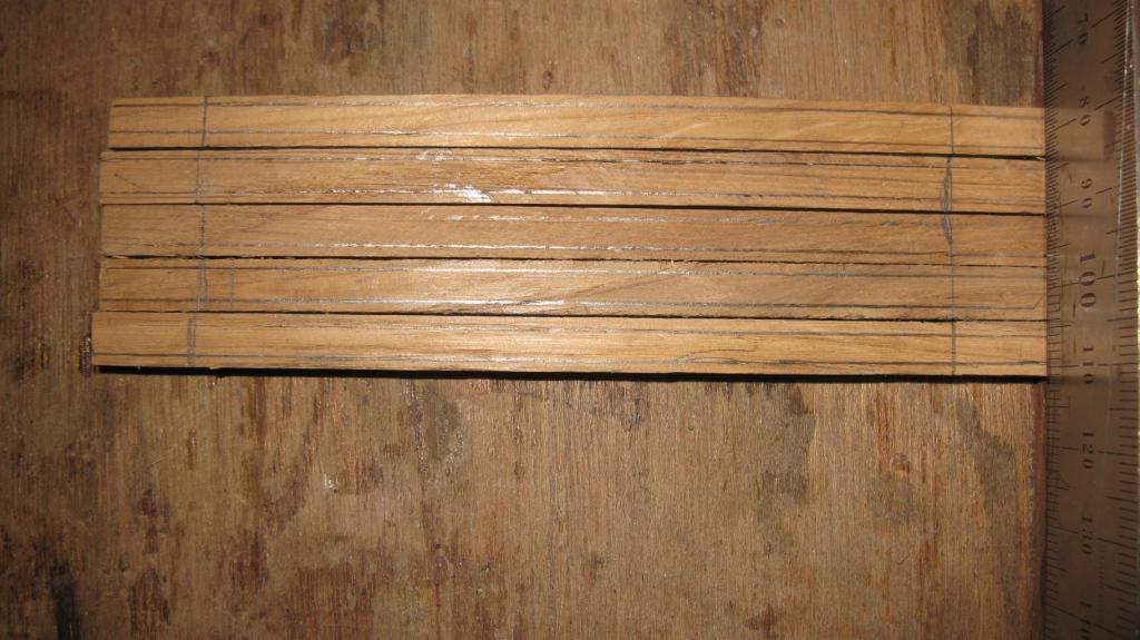
The result of an afternoon of carving:
-
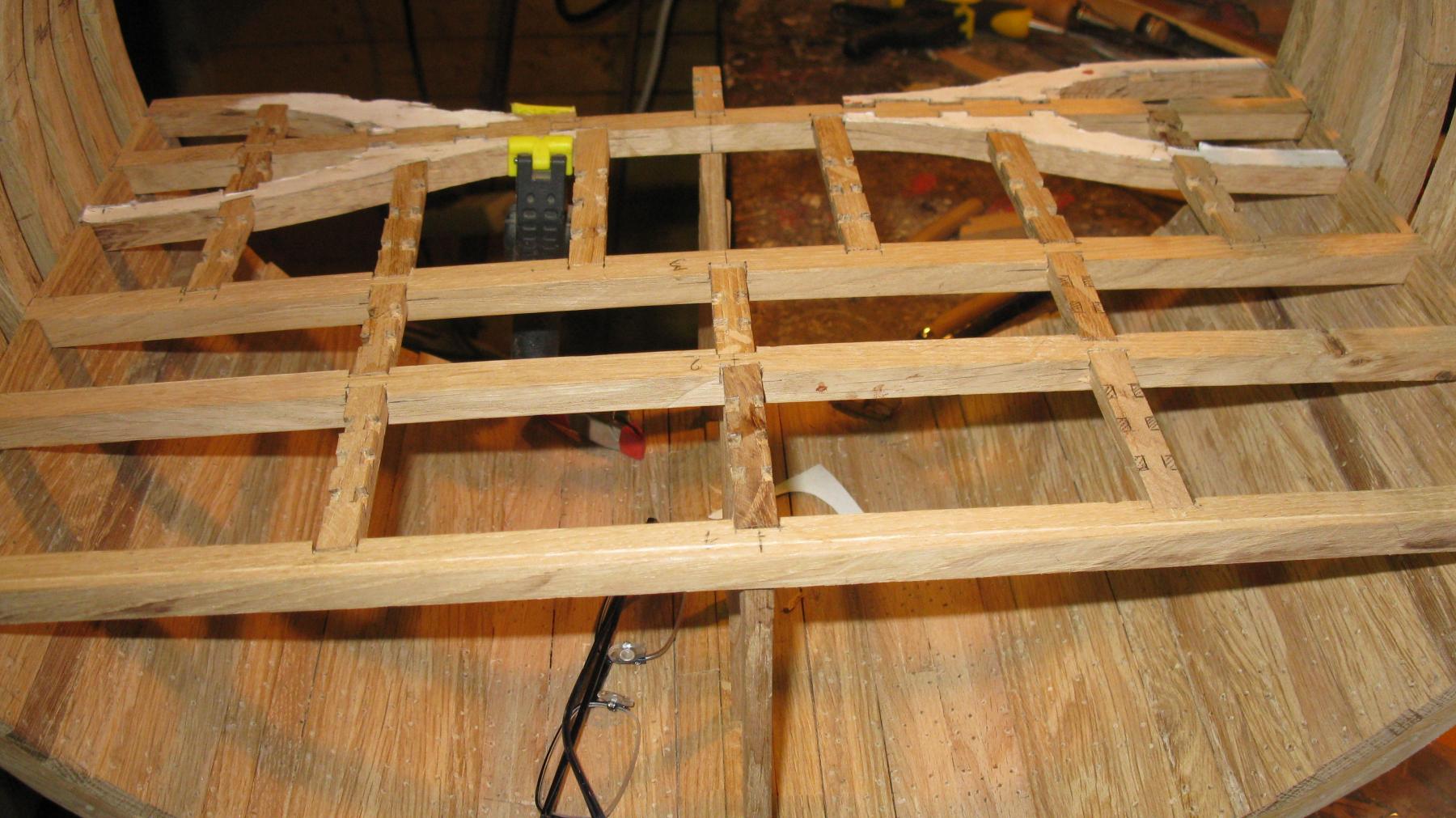
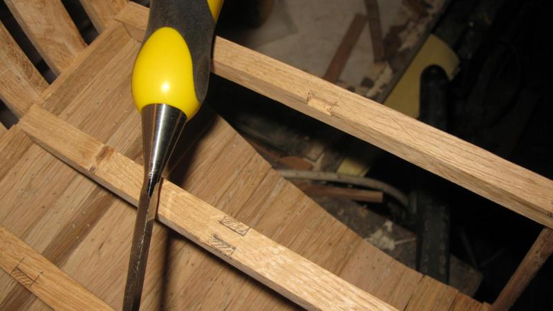
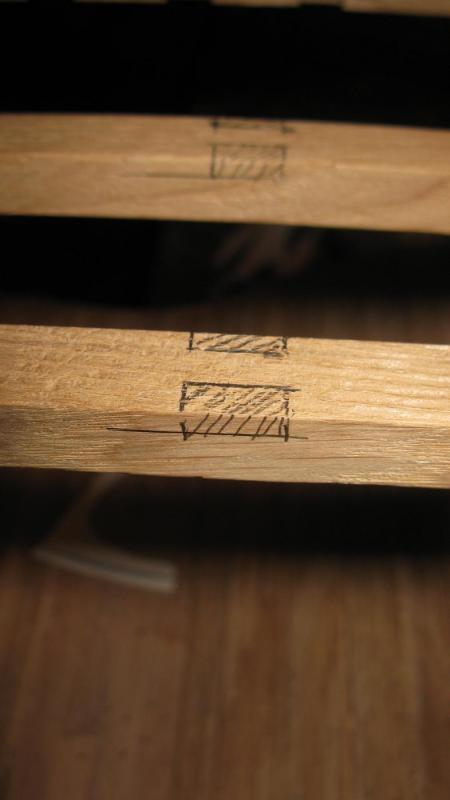
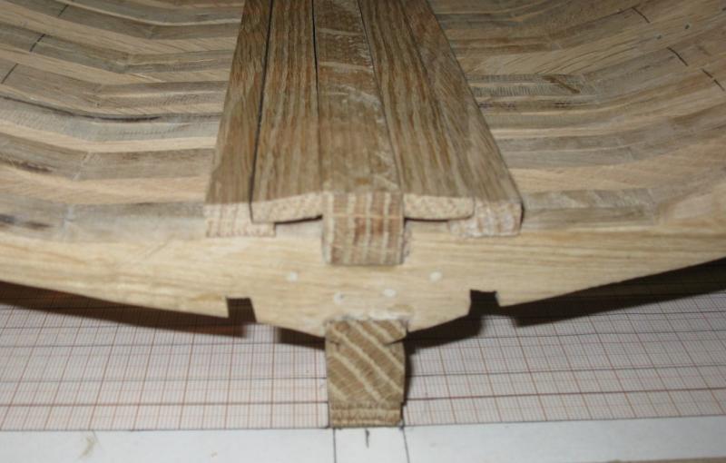
Anyway, I make the notches for the ledges in the carlings while they are still removable.

-
... and it works!
-
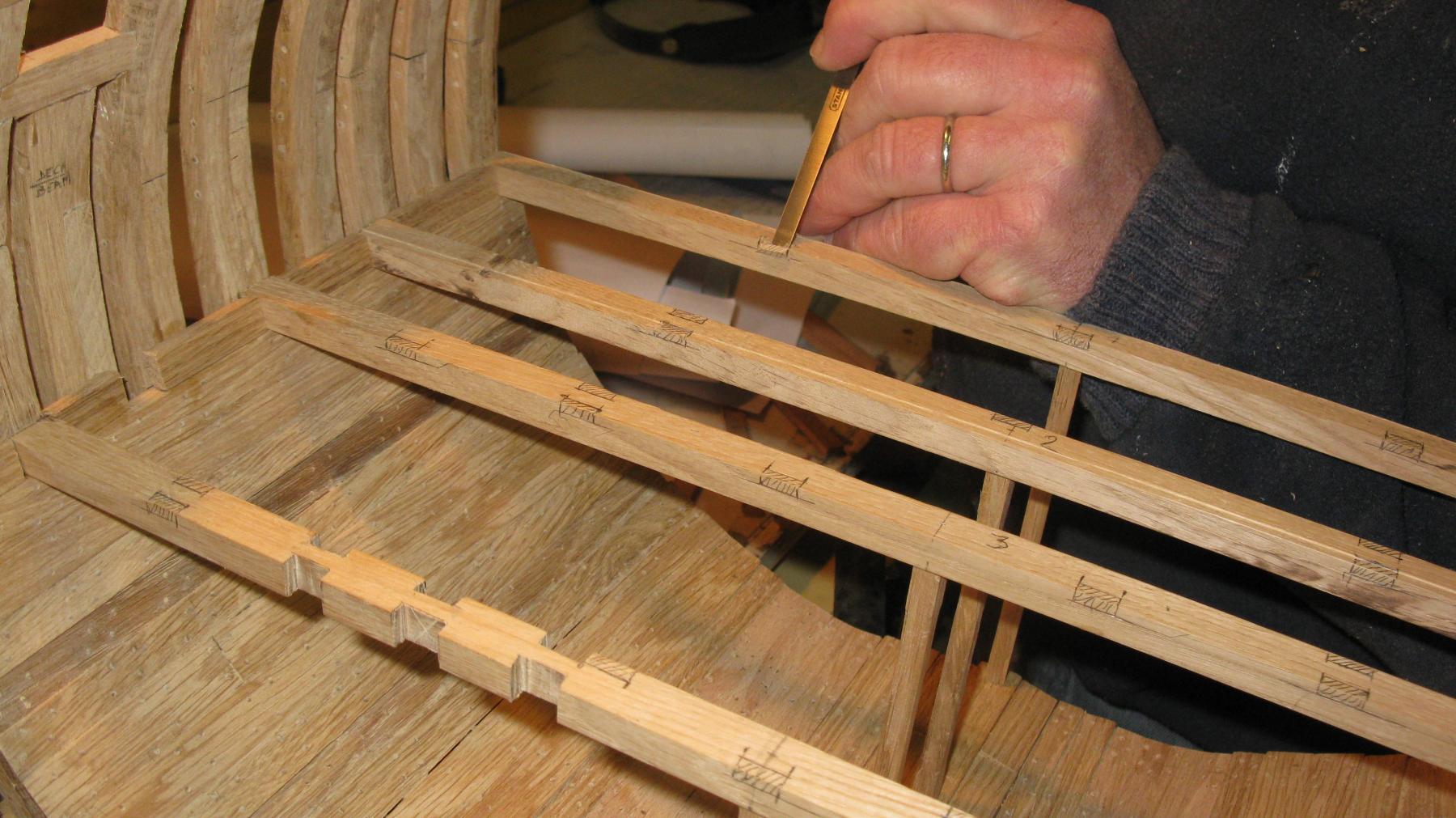
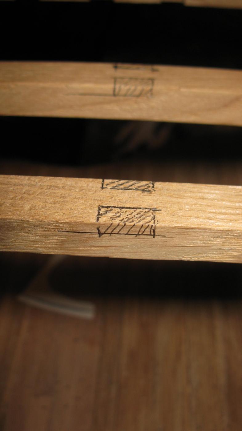
While drawing the notches for the carlings on the deck beams, I realize that it would have been better to carve them before fastening the deck beams. Anyway it is too late now, I have to carve them while they are in place. I learned my lesson for the gun deck.

-
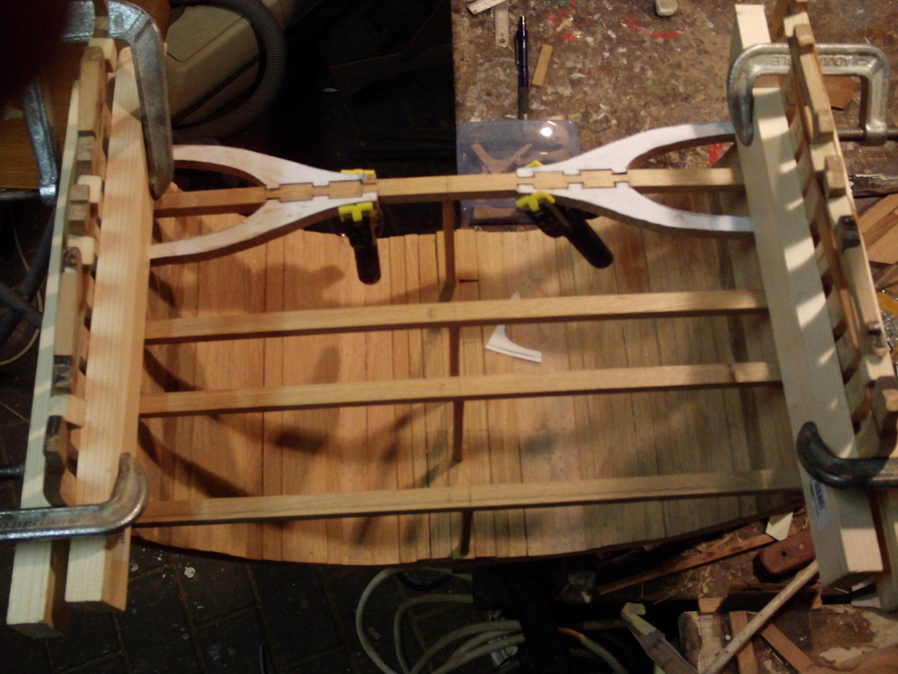
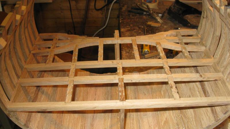
Now they are glued at the correct interspaces.
-
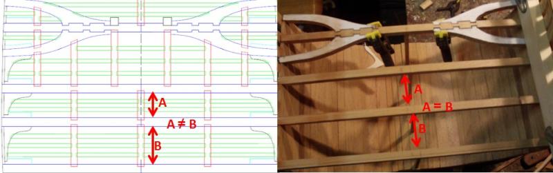
I did not see my mistake before everything was dry and fixed: I didn't look to the plan before fixing the deck beams and glued N° 1 to 3 at equal distances. That means: unfasten deck beam N° 3 and replacing it.
-
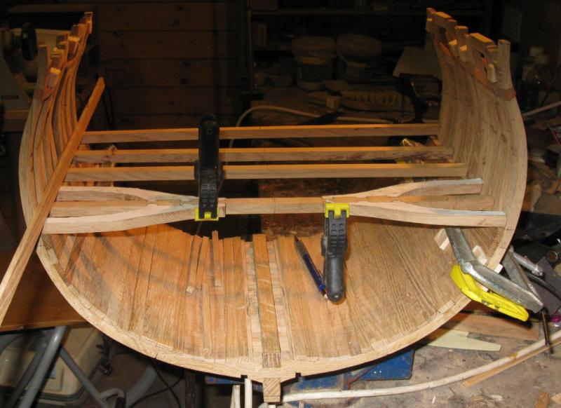
Now I can glue the deck beams in place. To fix the pillars, I drill a hole for a bamboo pin in both sides of the pillar and also on the locations where they will stand on the keelson and in the deck beams.

-
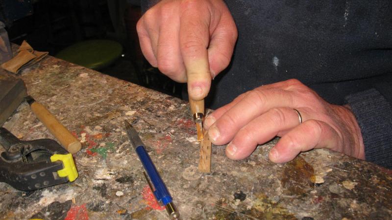
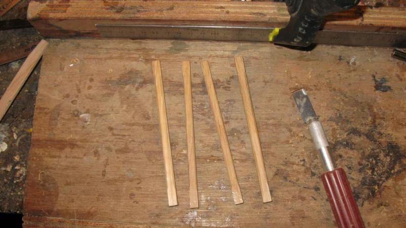
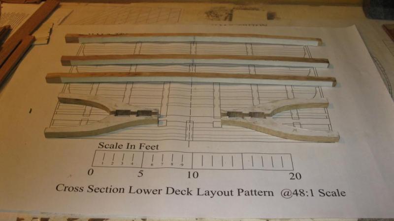
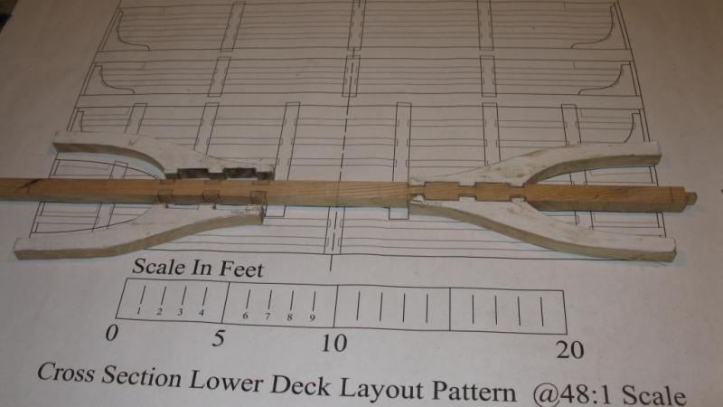
The deck beams are made, now I make the 4 hold pillars. I make five in case one of them is not good. On the plan they are represented as square pillars, I will round off the corners. I do it with a small chisel.

-
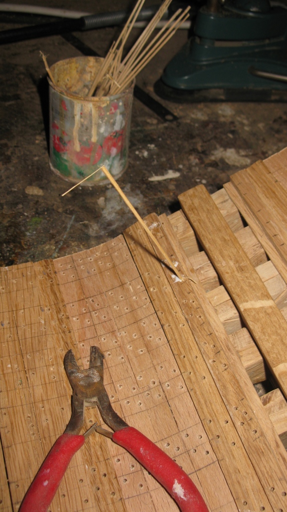
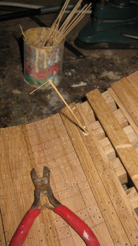
When the tree nails are glued, it is time to sand the lower deck. To reach the narrow planks which are thinner then the surrounding planks, I made a sanding block of a piece of plywood.

-
Thank you Allen, but do not overrate my skills, I am rather new in ship modeling. Tree nailing is a bit a boring job. I didn't count them but at this stage I have to drill some hundreds of holes and fill them again with as much bamboo nails.

-
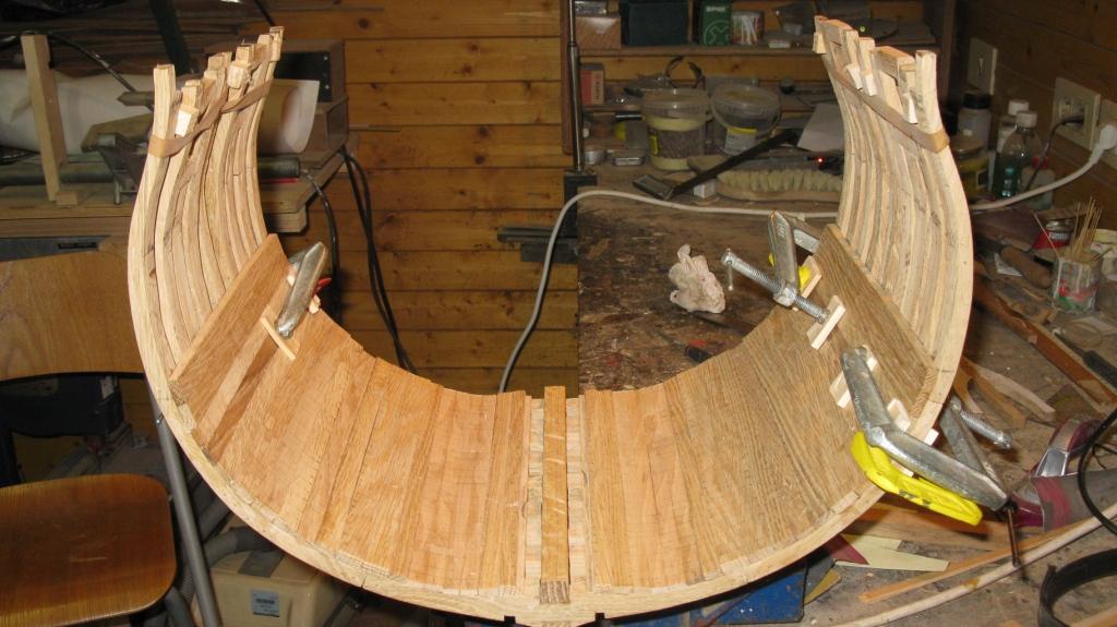
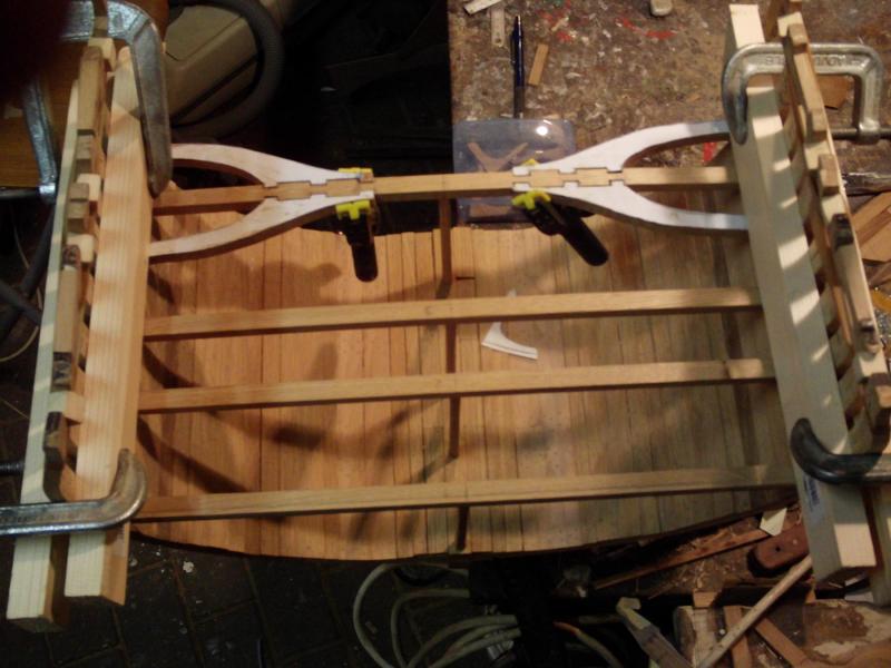
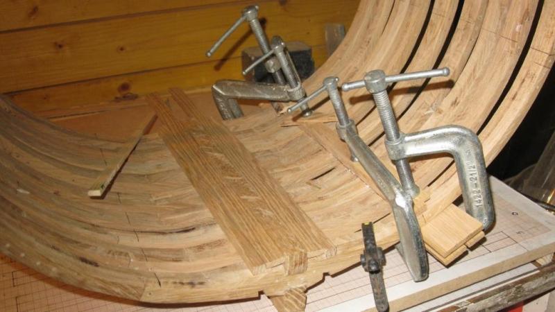
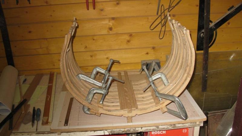
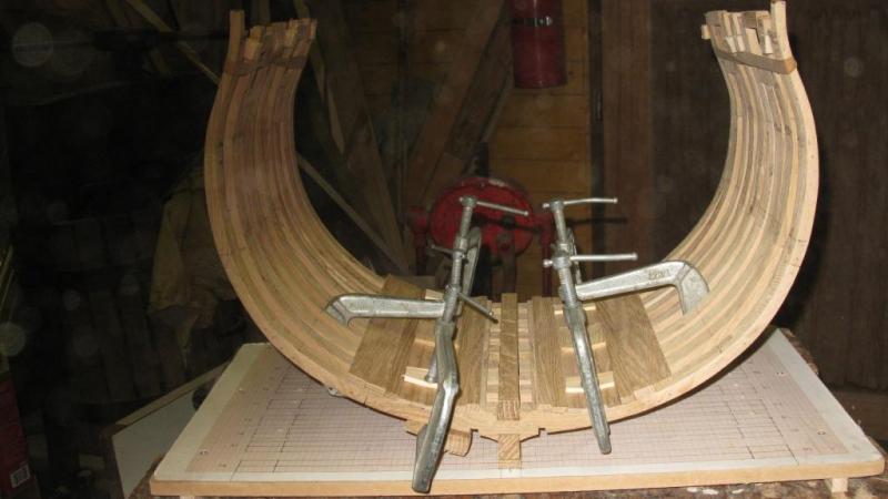
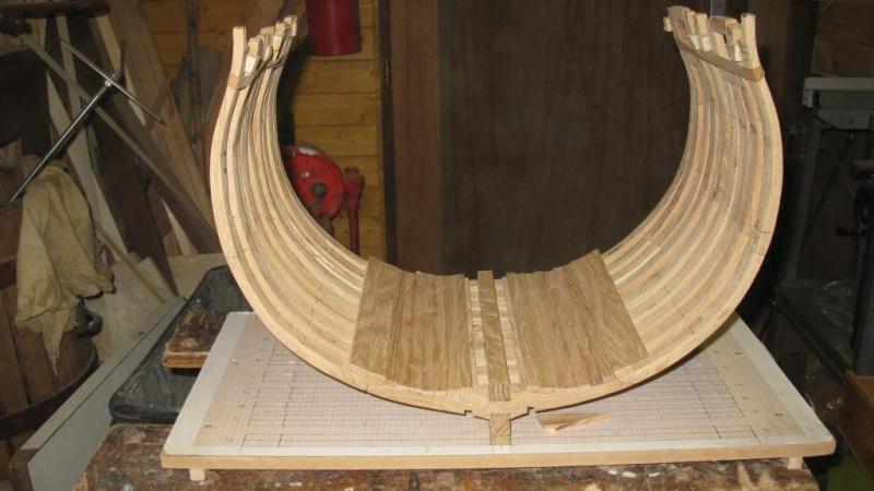
While the glue is drying I start to make the lower deck beams and the lower deck beam arms. On the fourth picture the deck beams are laid in the model but not yet fastened. Before I will do that, the lower deck has to be tree nailed.
-
The deck clamps are in place and the last gaps in the planking are filled.

-
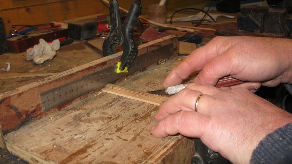
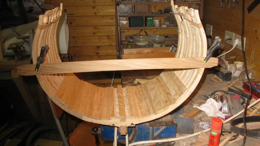
Some special attention is to be drawn to the lower deck clamp. To determine the angle of the upper side of the plank I fasten with clamps a lath on the bottom level of the lower deck beam. I hold a piece of cardboard against the frame and mark the lined of the bottom deck beam and the frame. This cardboard will be the template to saw the deck beam.


-
Next thing to do is fixing the inner planking of the lower deck.
-
Pete and Mark, Thank you very much for this useful information. Geert
-
Thank you Mark, I have a question about the limber boards. I guess they were removable to check the level of the water in the bilges. I suppose they were shorter than the lenght of the cross section and there were (finger)holes in it in order to make it easier to lift them up. Do you have an idea of the lenght and the look (from above) of the limber boards? Geert
-
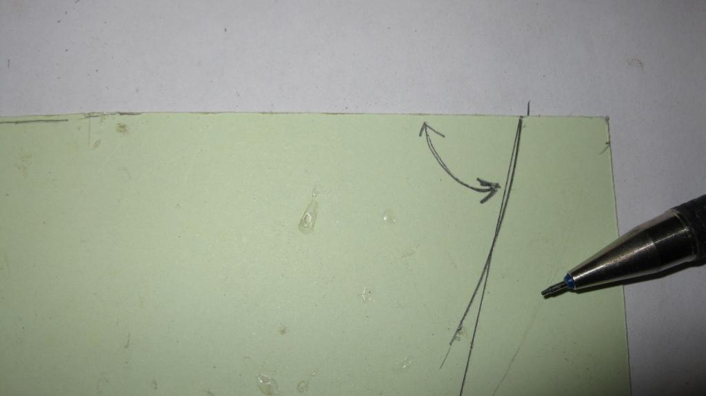
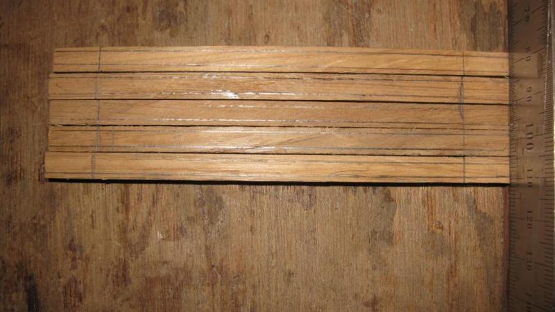
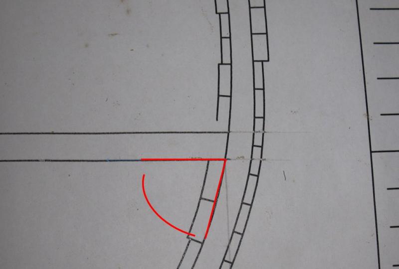
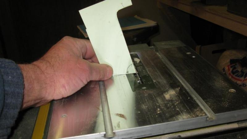
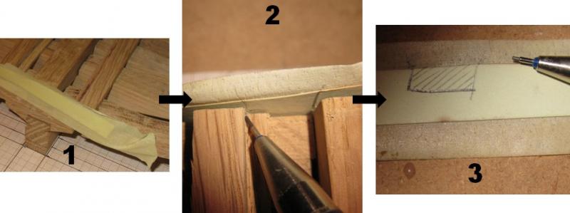
With the template I make a pattern of the angle to set up the angle of the Proxxon saw to saw the boards.
-
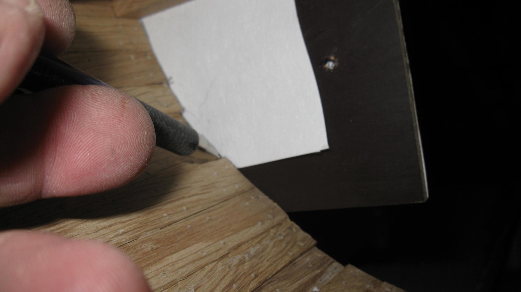
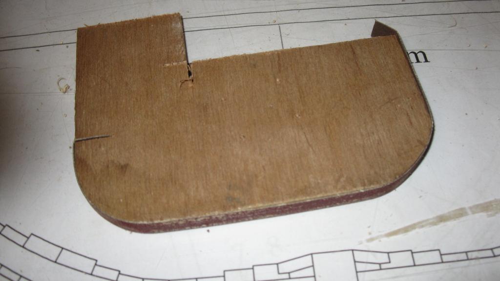
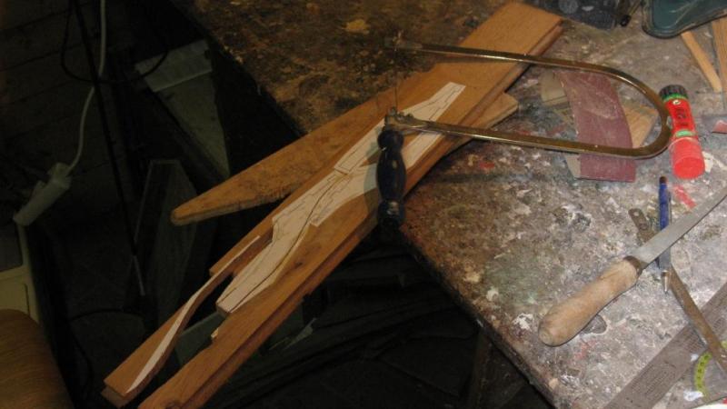
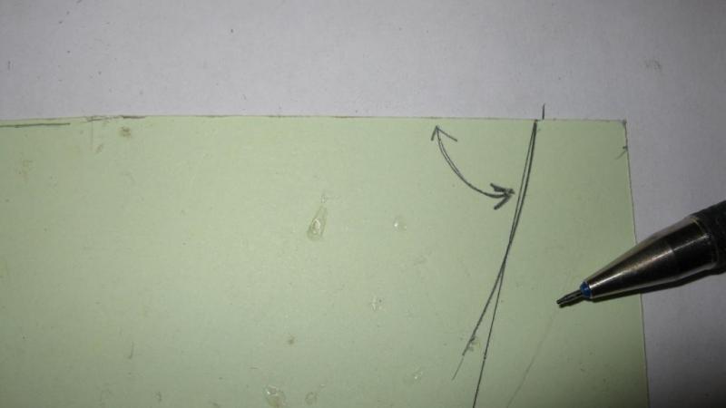
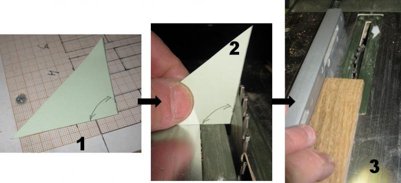
To determine the angle of the sides of the limber boards, I fix a piece of cardboard with some scotch tape on the end of the keelson and limber strake. This way it is easy to line the contours of the space between them. The result is a template of the limber board.
-
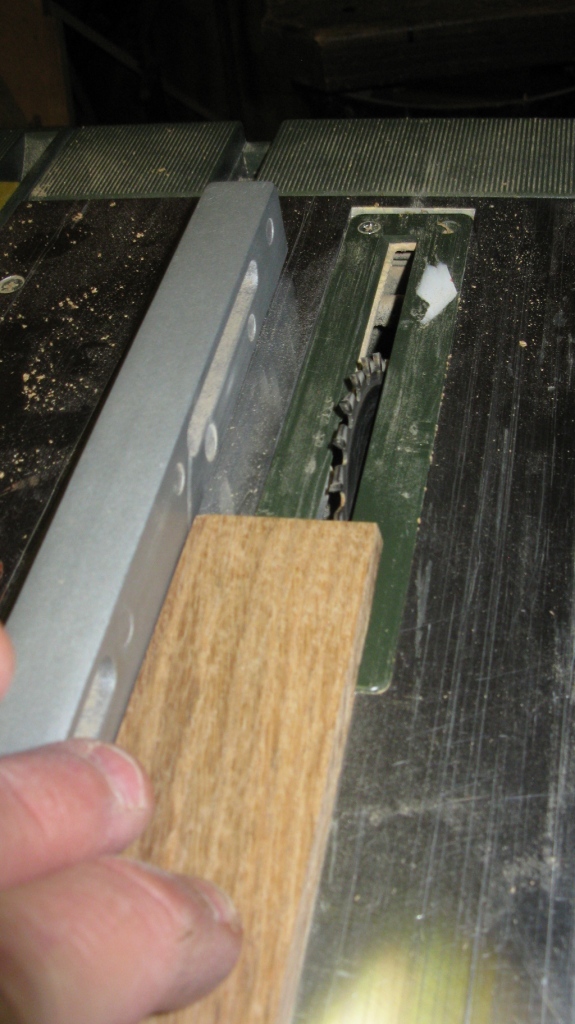
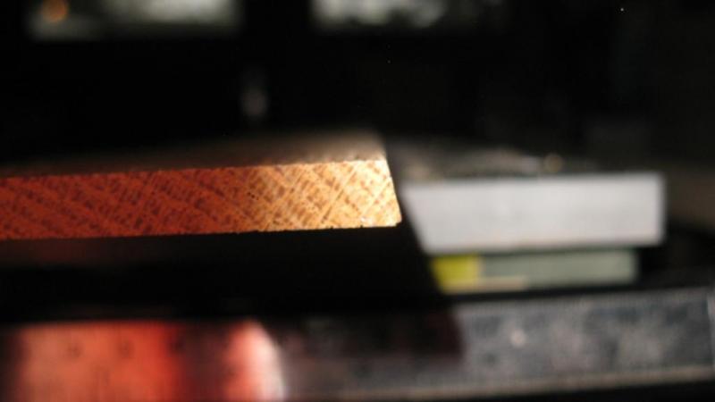
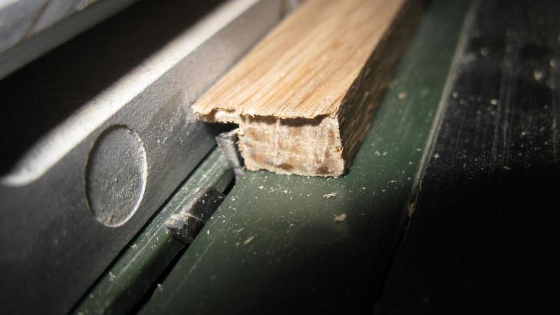
The grove in the limber strakes is made with the Proxxon saw

-
After the sanding I make the notches for the gun port lintels. As can be seen on the picture the frames on the port side are a bit to short below the gun port. Fortunately there will be planking on top of it.

-
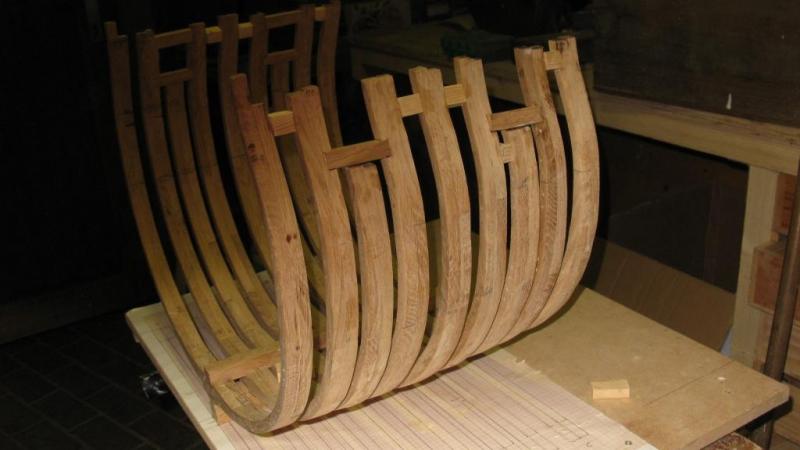
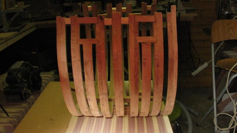
When all the frames are in place, It is time for a first sanding session. Thanks to the large scale, I can use normal tools. After sanding I install the keelson.

-
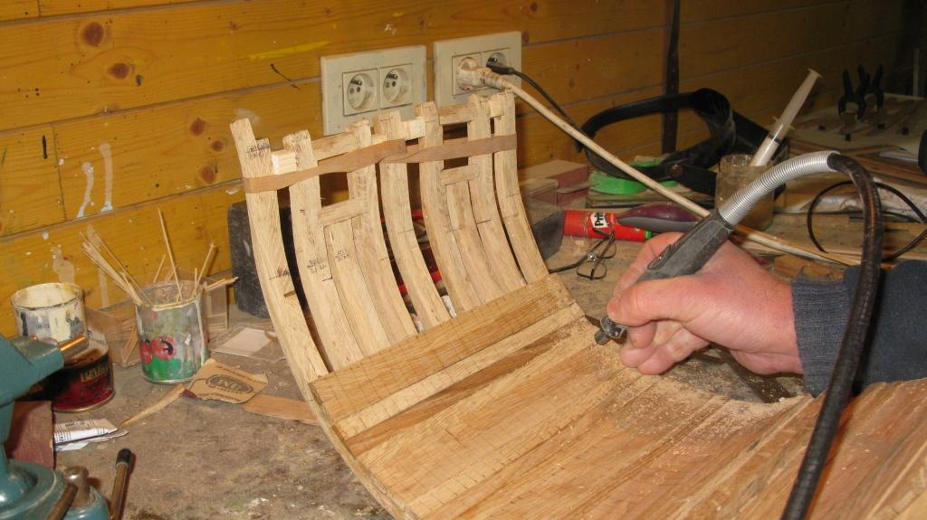
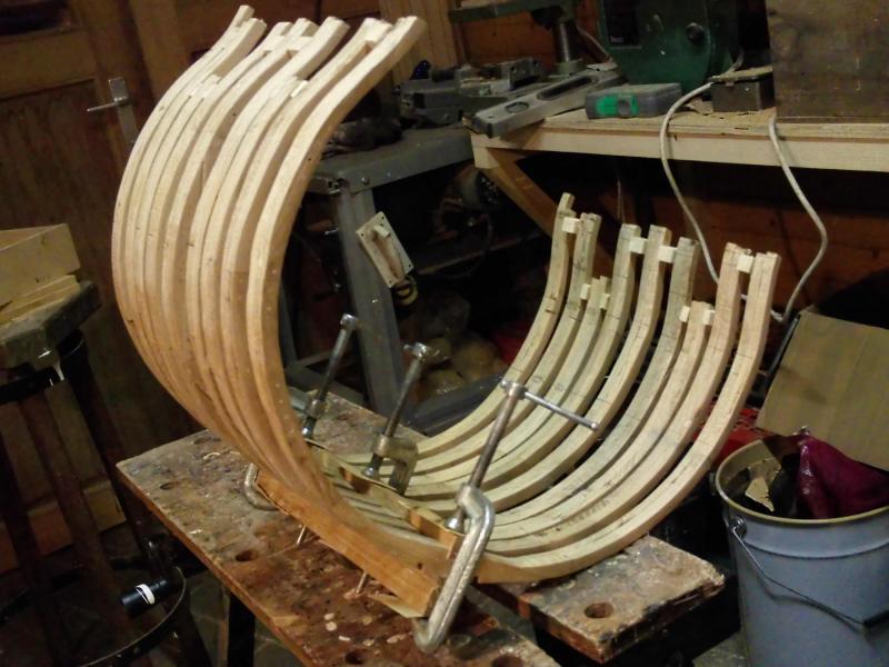
Between the frames, a small piece of wood is glued temporally to keep the correct distance from bottom to top.
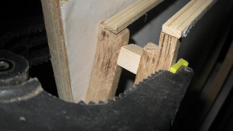
-
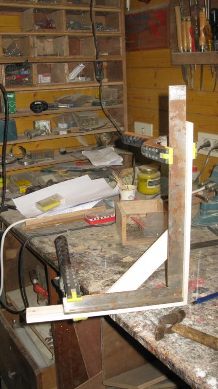
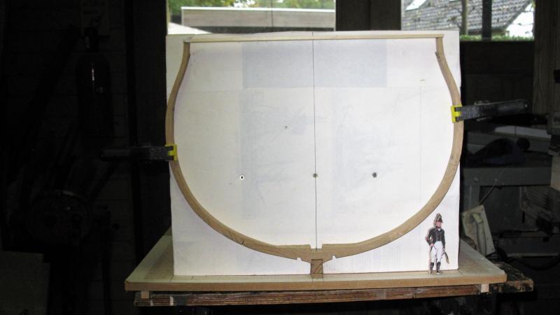
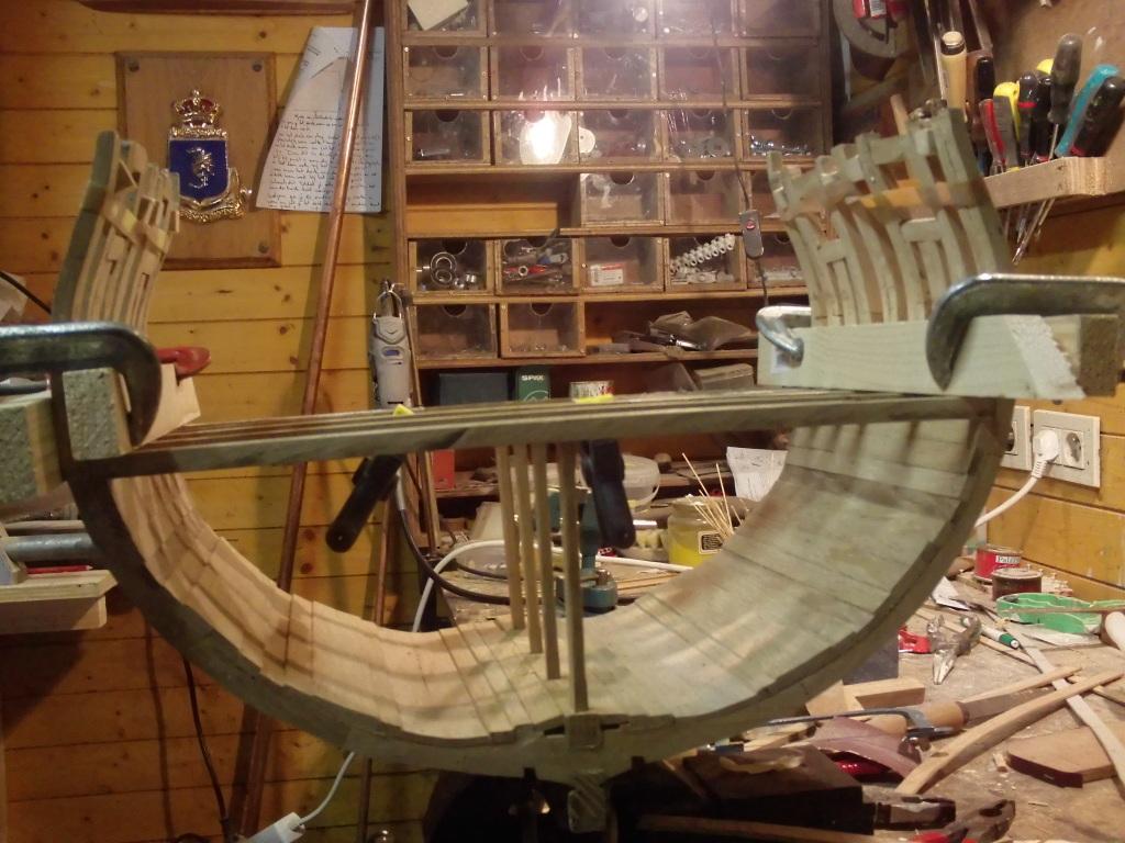
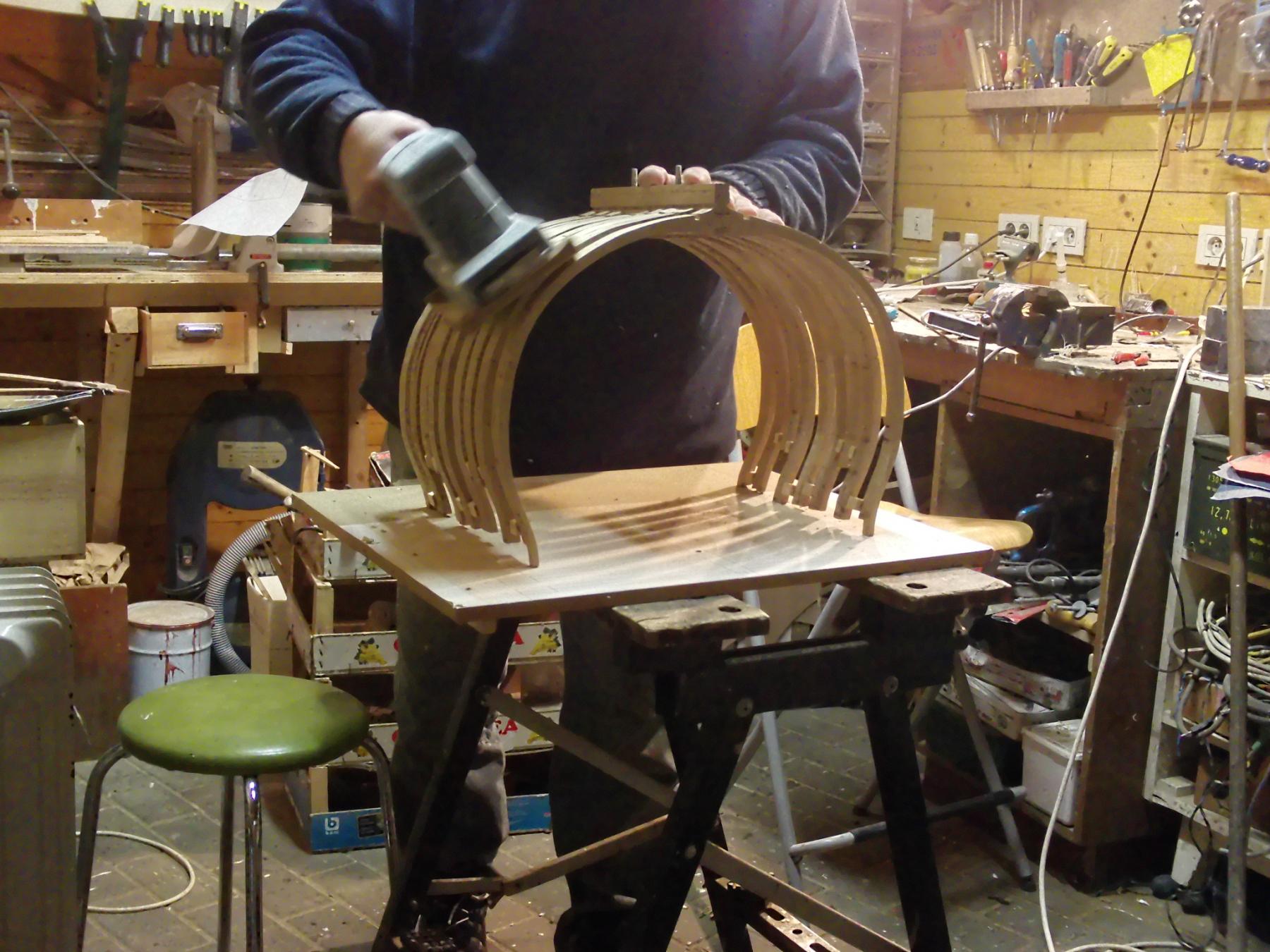
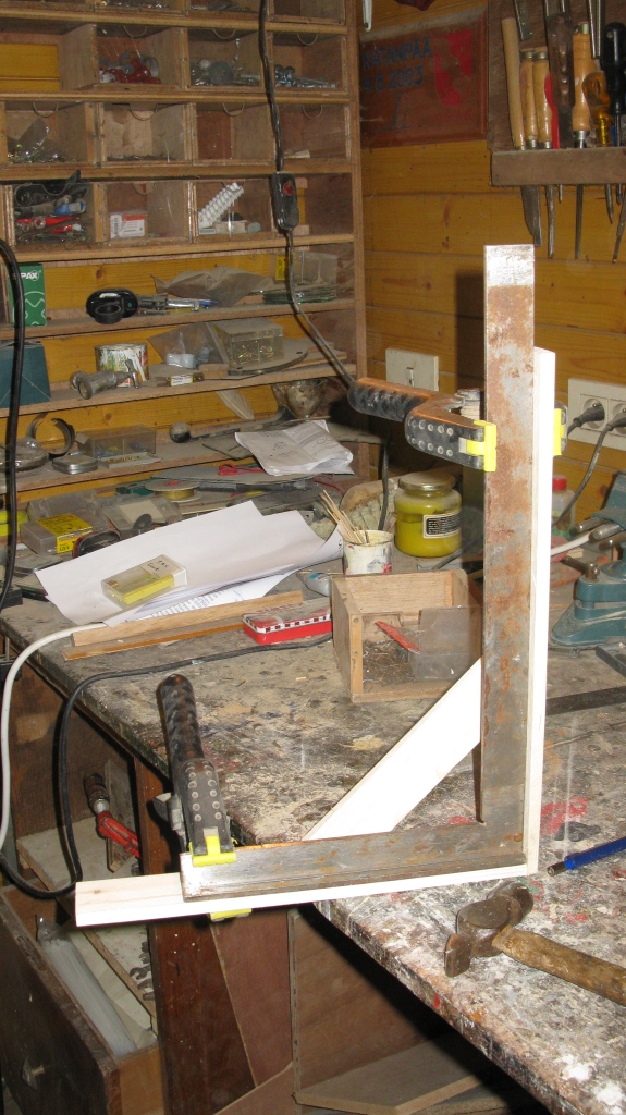
I wish all forum members a happy and prosperous New Year with a lot of modelling pleasure in 2017! Before going to the family this afternoon, I have some time to line up with the progress on the cross section. As an aid to place the frames vertical, I made two wooden perpendicular supports which keep a shelf vertical. On the shelf the middle line of the cross section is drawn. That will be my aid to glue the frames on the keel. The lieutenant on the second picture is in scale 1,70 m high, just to have an idea of the proportions