HOLIDAY DONATION DRIVE - SUPPORT MSW - DO YOUR PART TO KEEP THIS GREAT FORUM GOING! (Only 24 donations so far out of 49,000 members - C'mon guys!)
×


aydingocer
-
Posts
916 -
Joined
-
Last visited
Content Type
Profiles
Forums
Gallery
Events
Everything posted by aydingocer
-
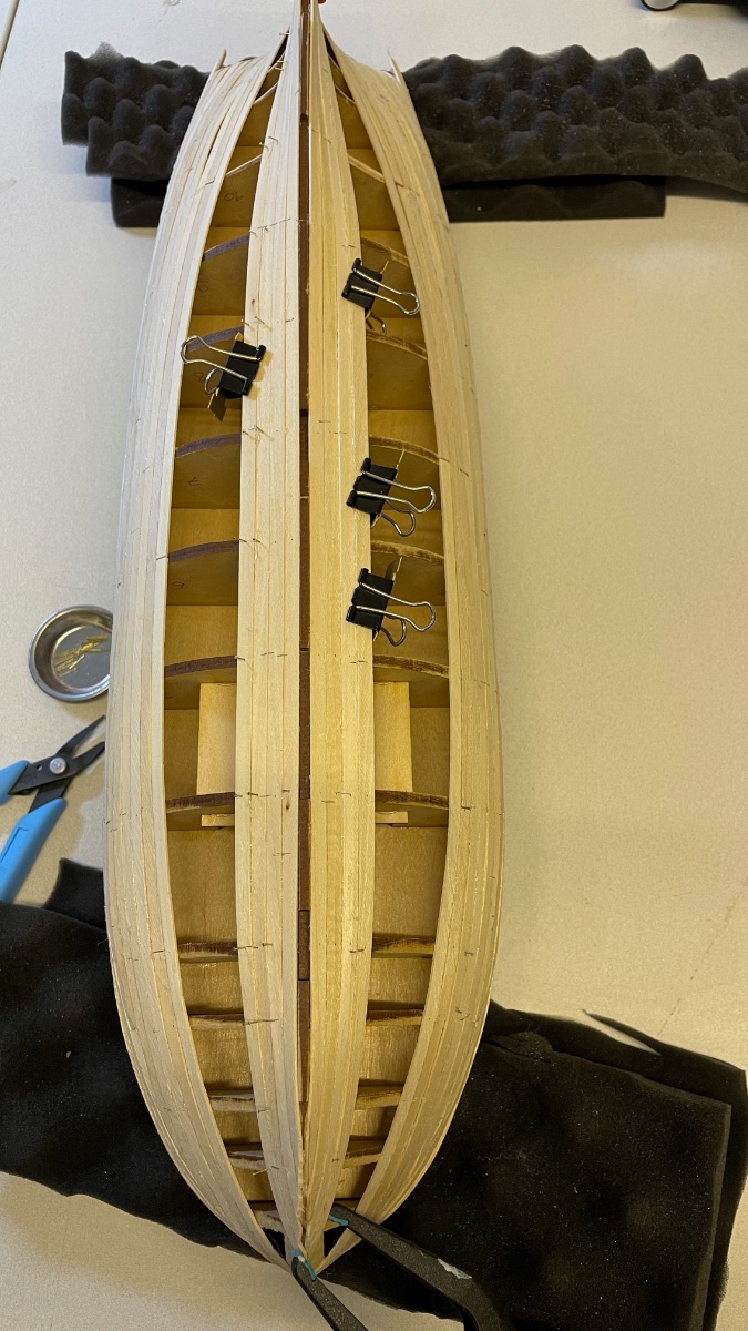
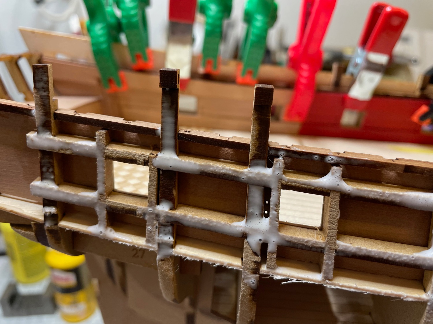
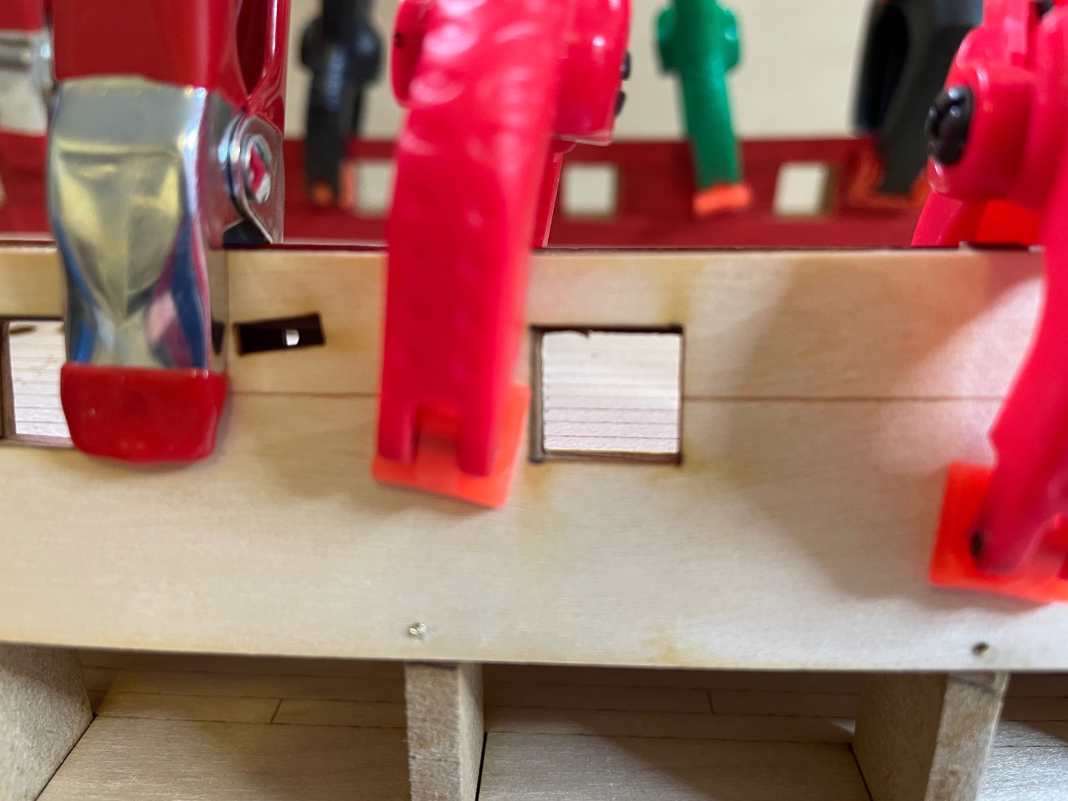
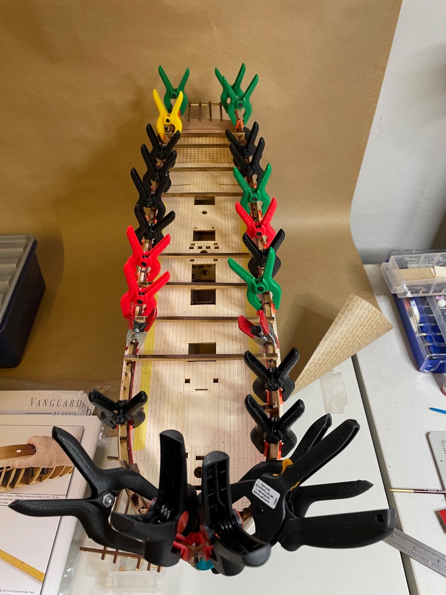
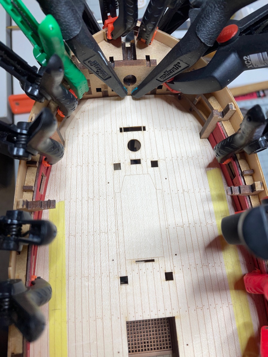
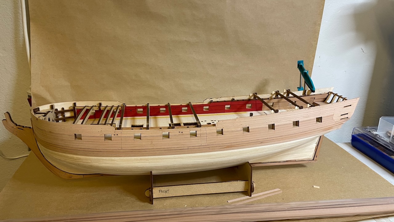
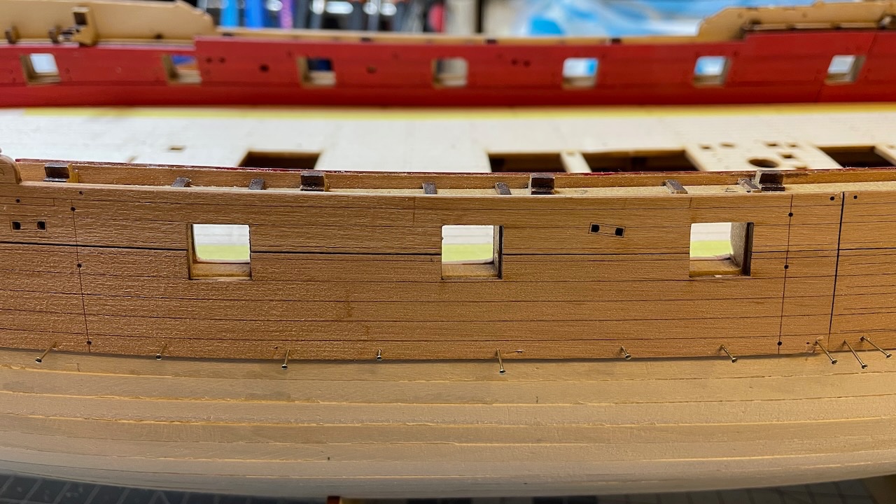
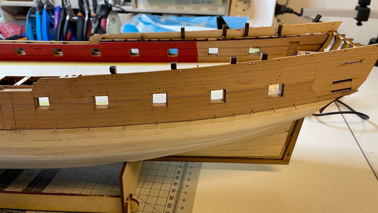
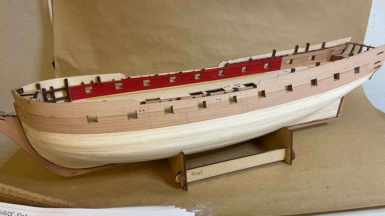
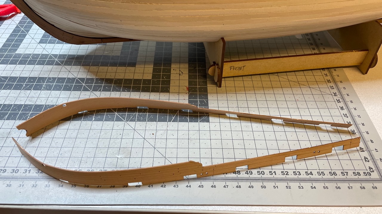
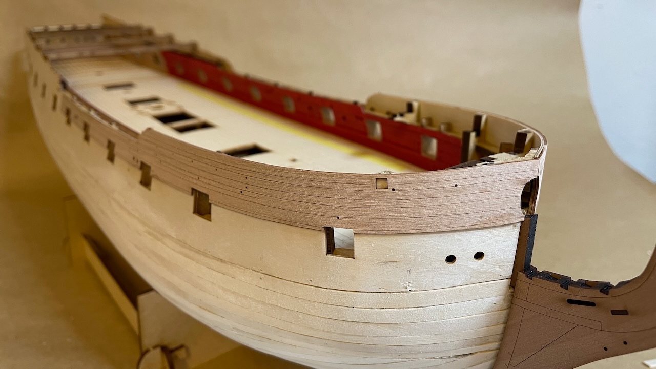
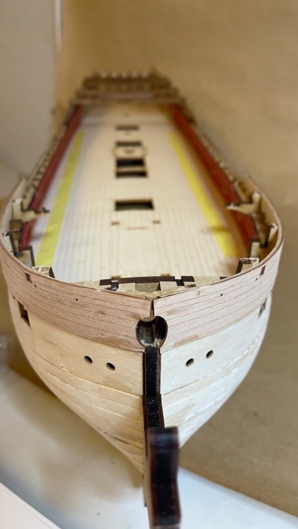
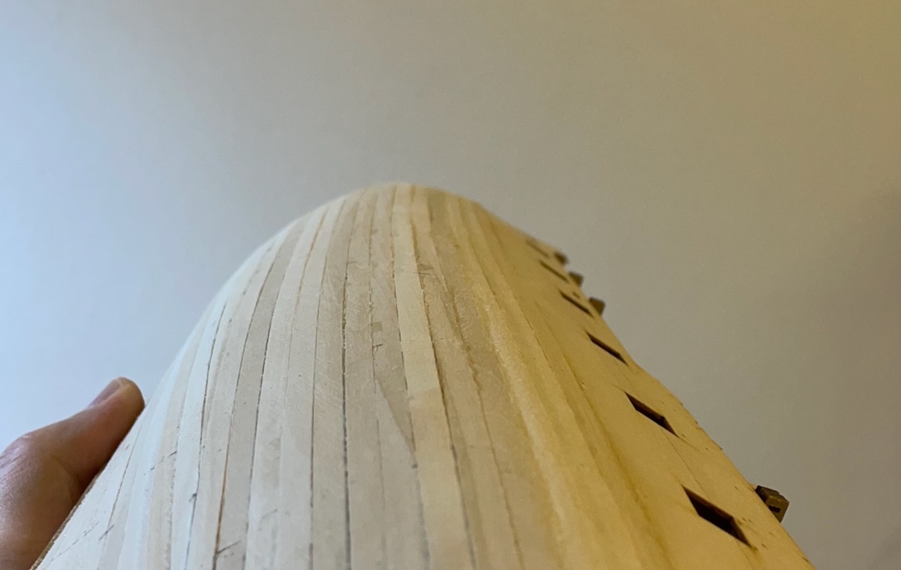
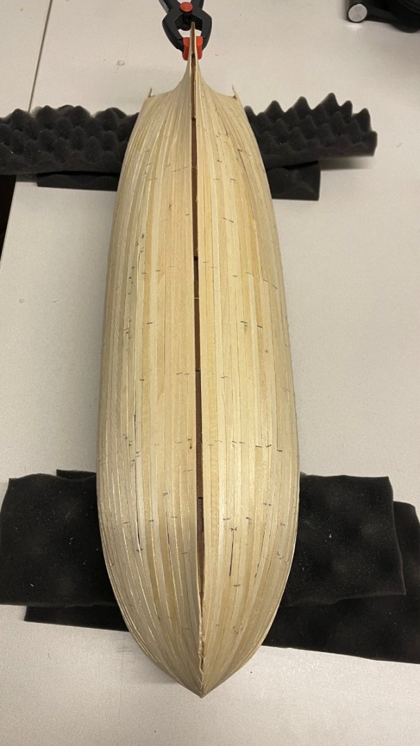
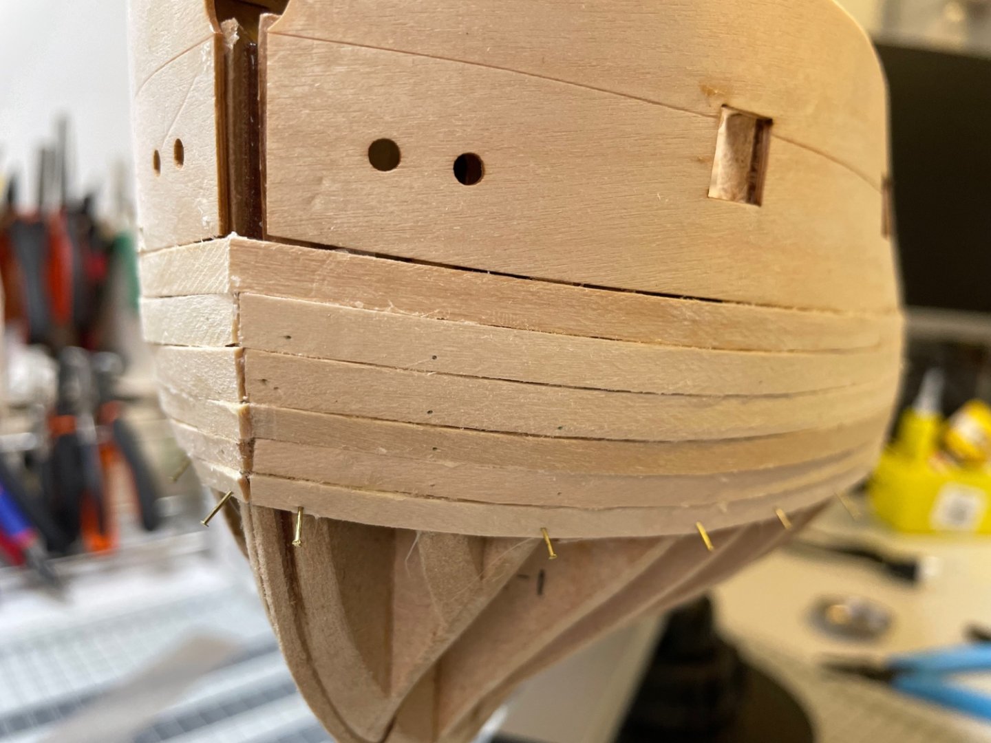
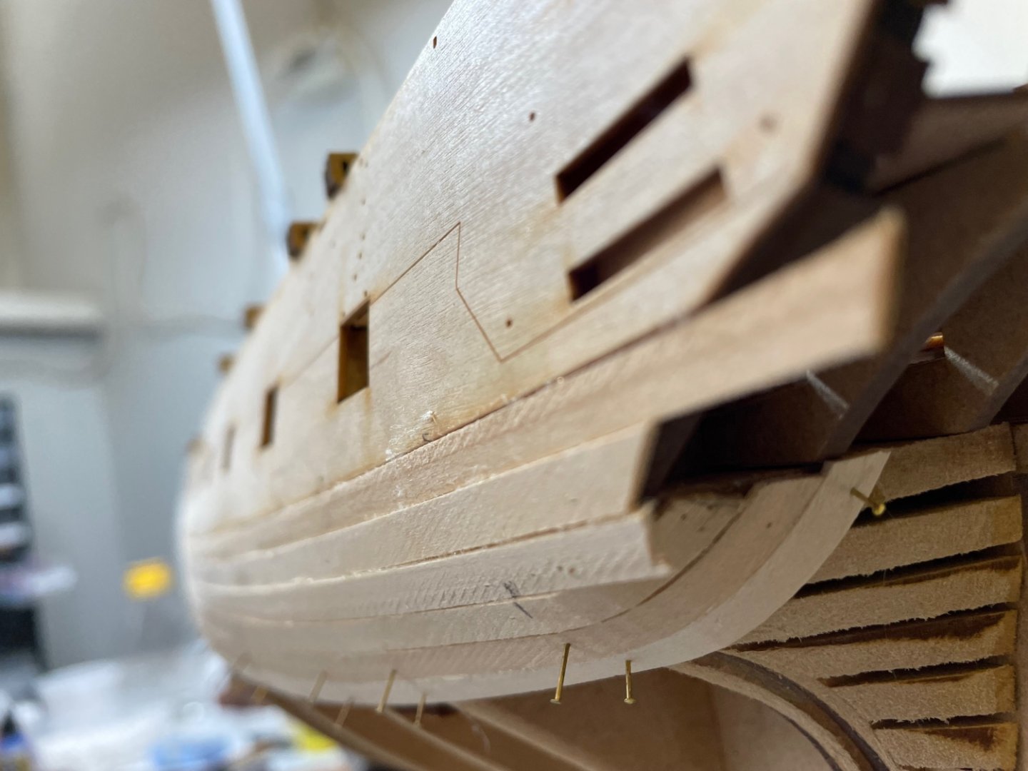
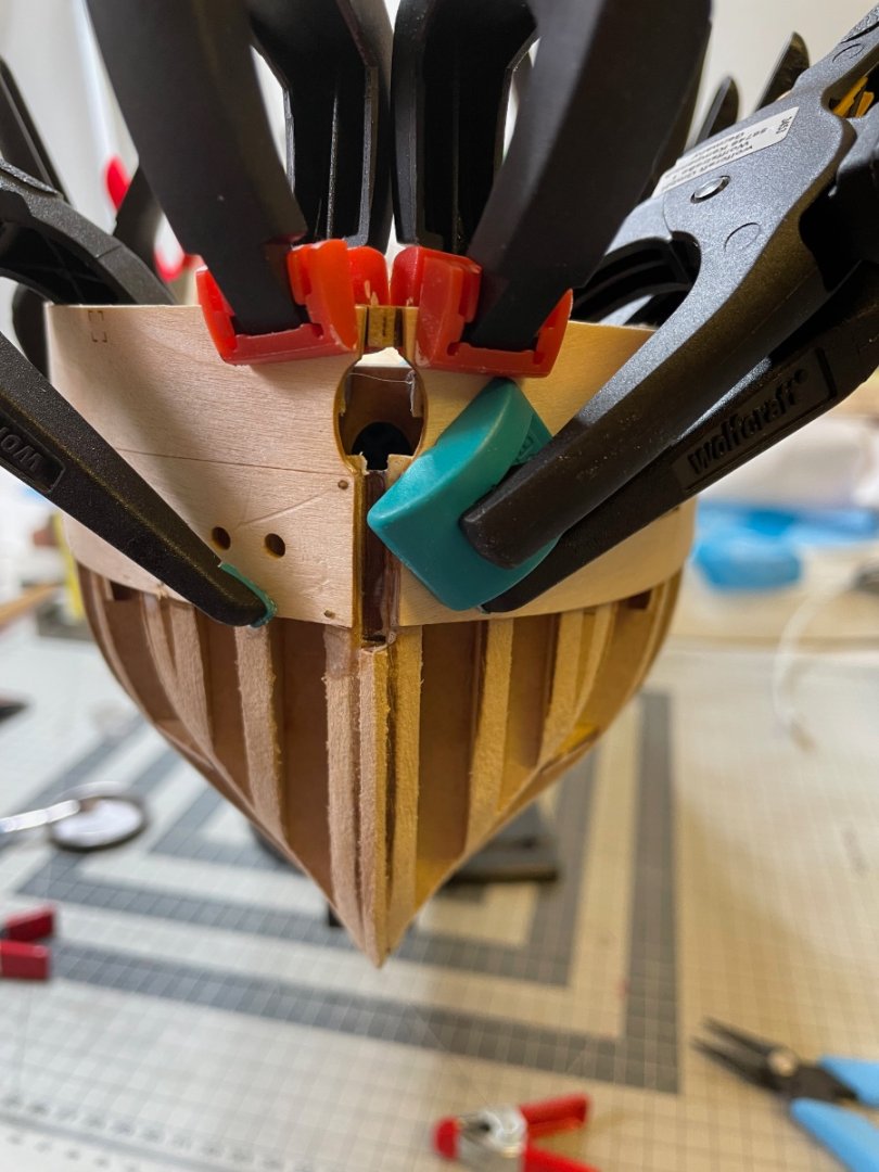
 BUILD DAYS 27-30: 14hrs / Total 60 hours Photo 260: 2nd planking is finished. Now the hull is ready for preparing to remove the jigs and its parts before sanding. I used UHU Hart glue and spots of super glue for securing quickly at the ends.
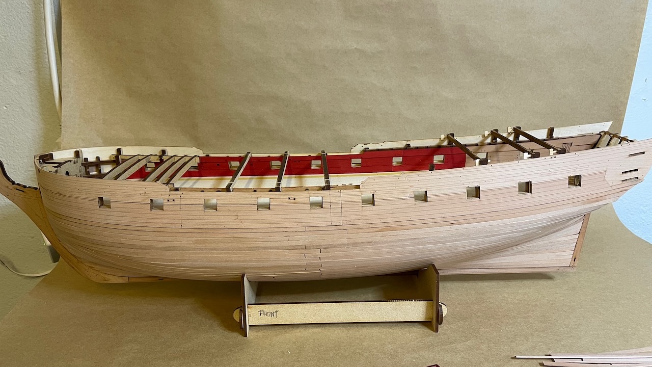
- 426 replies
-
- 3
-

-
- Vanguard Models
- Sphinx
- (and 1 more)
-
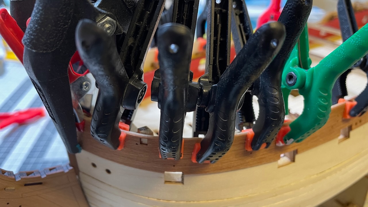
BUILD DAY 26: 1 hour / Total 46 hours Photo 259: Continued planking with two rows of pre-cut pear planks and one row of pear strips.
- 426 replies
-
- 6
-
-
- Vanguard Models
- Sphinx
- (and 1 more)
-
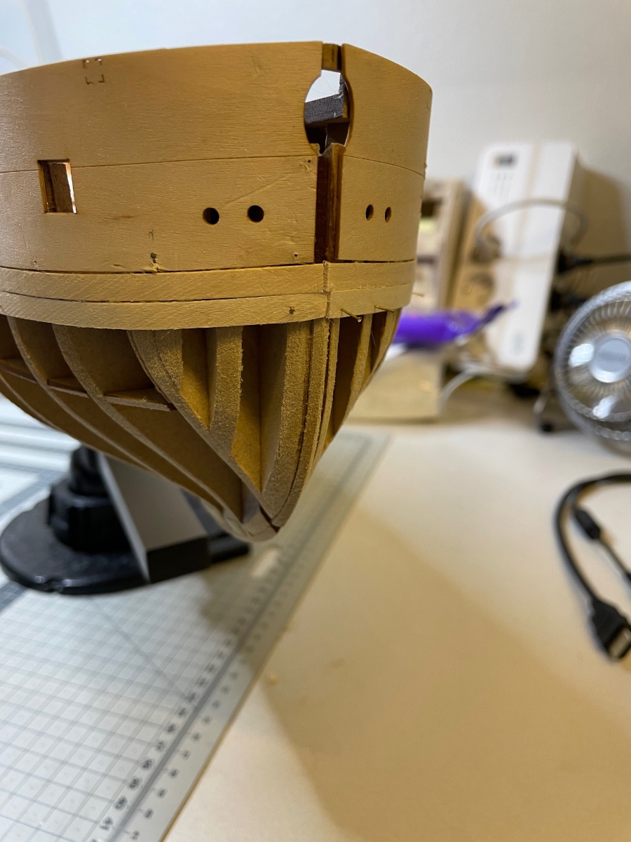
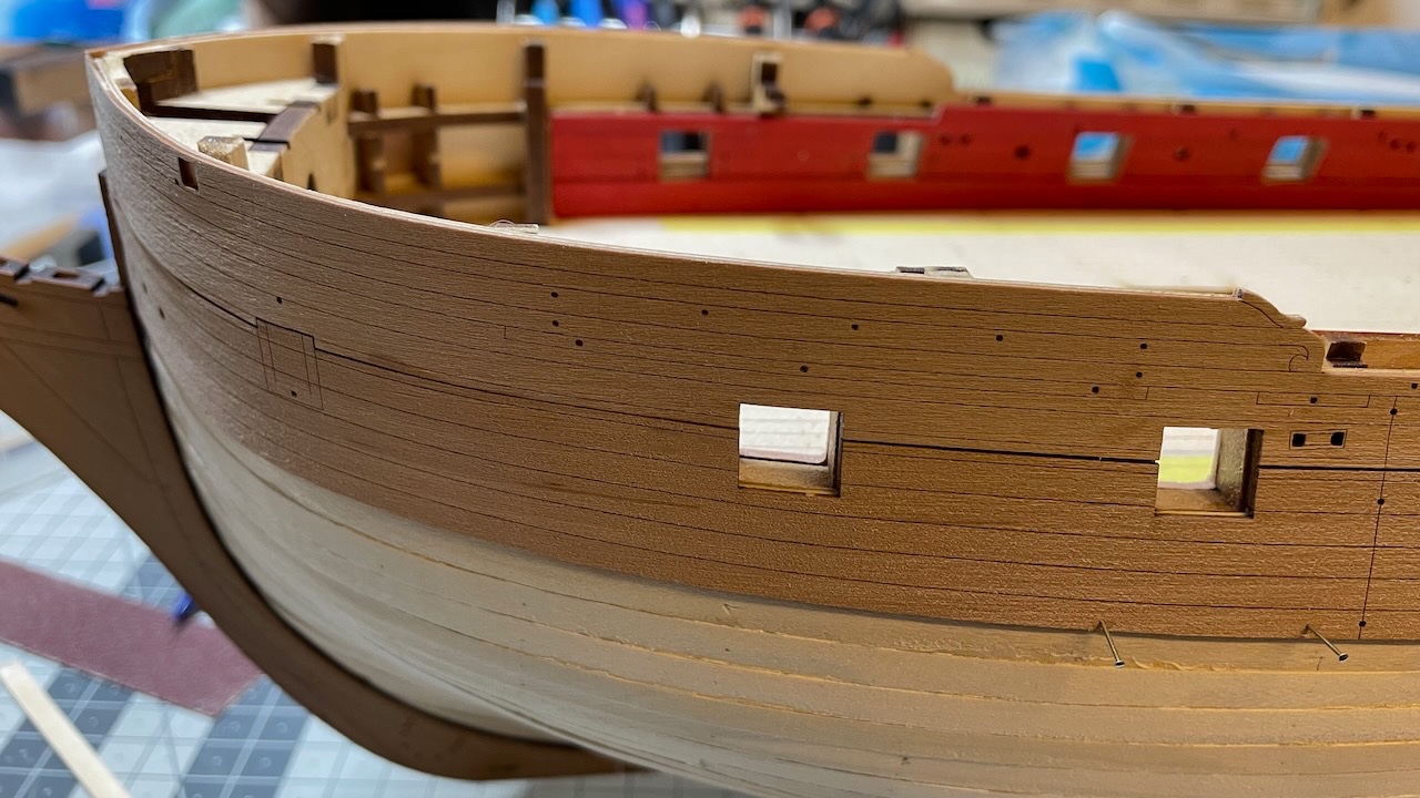
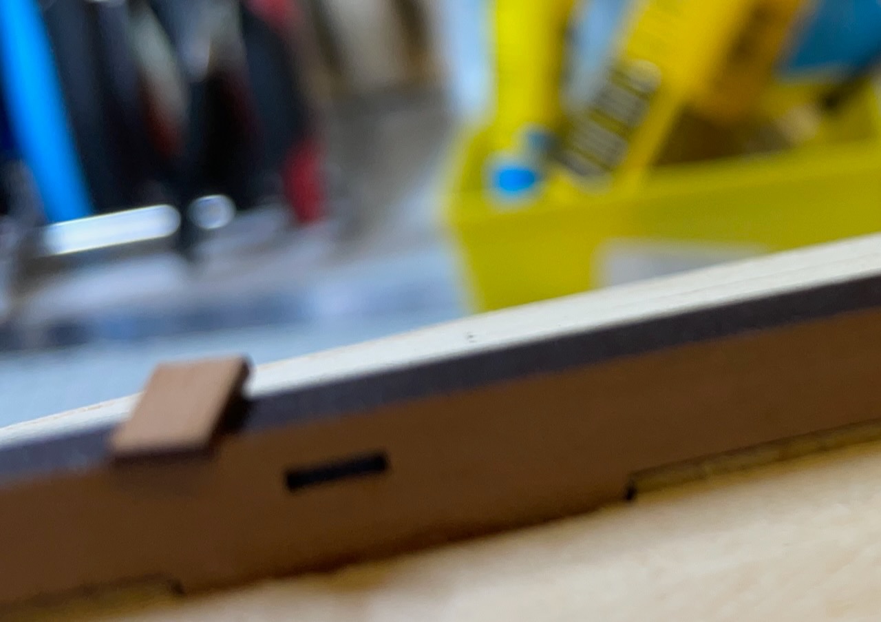
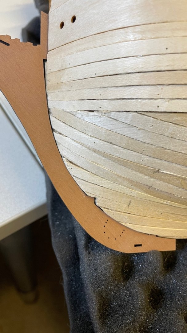
BUILD DAY 25: 1 hour / Total 45 hours ----- Photo 255-258: Aft Outer Planking Patterns (271, 273), Front lower Outer Planking Patterns (305, 307), Rear lower Outer Planking Patterns (306, 308) are also now glued in place, after soaking and bending where necessary.
- 426 replies
-
- 5
-
-
- Vanguard Models
- Sphinx
- (and 1 more)
-
BUILD DAY 24: 0.5 hours / Total 44 hours ----- Photo 252-254: Fore outer planking patterns now properly dried, aligned and glued perfectly in place. I followed the recommendation in the instructions: applying diluted white glue on the hull.
- 426 replies
-
- 4
-
-
- Vanguard Models
- Sphinx
- (and 1 more)
-
Photo 251: Fore outer planking patterns. Soaked in hot water and clamped in position, waiting to dry... this time completely, I promise 🤣!
- 426 replies
-
- 3
-
-
- Vanguard Models
- Sphinx
- (and 1 more)
-
BUILD DAY 23: 1.5 hours / Total 43.5 hours Photos 247-248: The idea of these location pegs alone is enough reason to prefer this kit. Great help! Photos 249-250: This way you achieve the most precise alignment of outer Prow-, Keel- and Rudder outer patterns
- 426 replies
-
- 2
-
-
- Vanguard Models
- Sphinx
- (and 1 more)
-
That's most probably the case. It is the first time I am working with pear and I have to admit it was not perfectly dry. I have left my workshop room for the day now and I'll see tomorrow how much it shrank. Luckily after all it will stay under the upper counter so I am hoping there is room for correction.
- 426 replies
-
- 2
-
-
- Vanguard Models
- Sphinx
- (and 1 more)
-
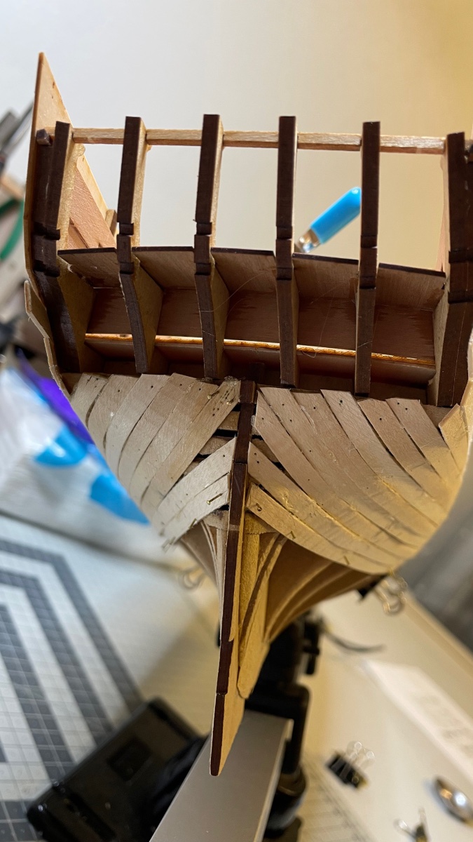
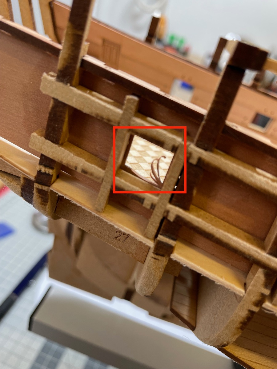
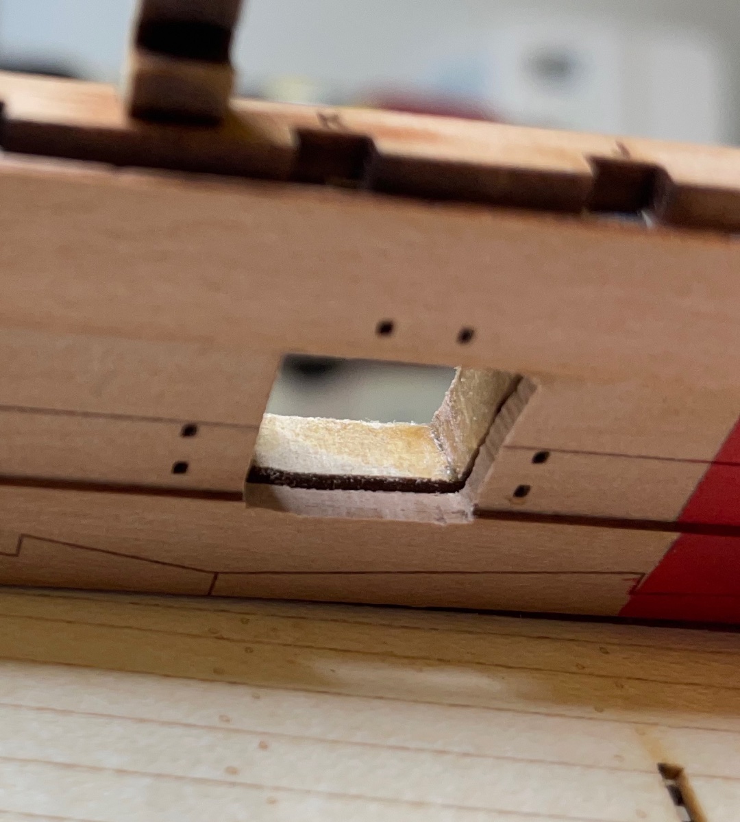
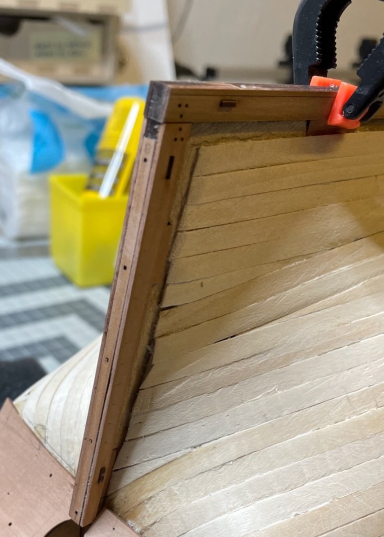
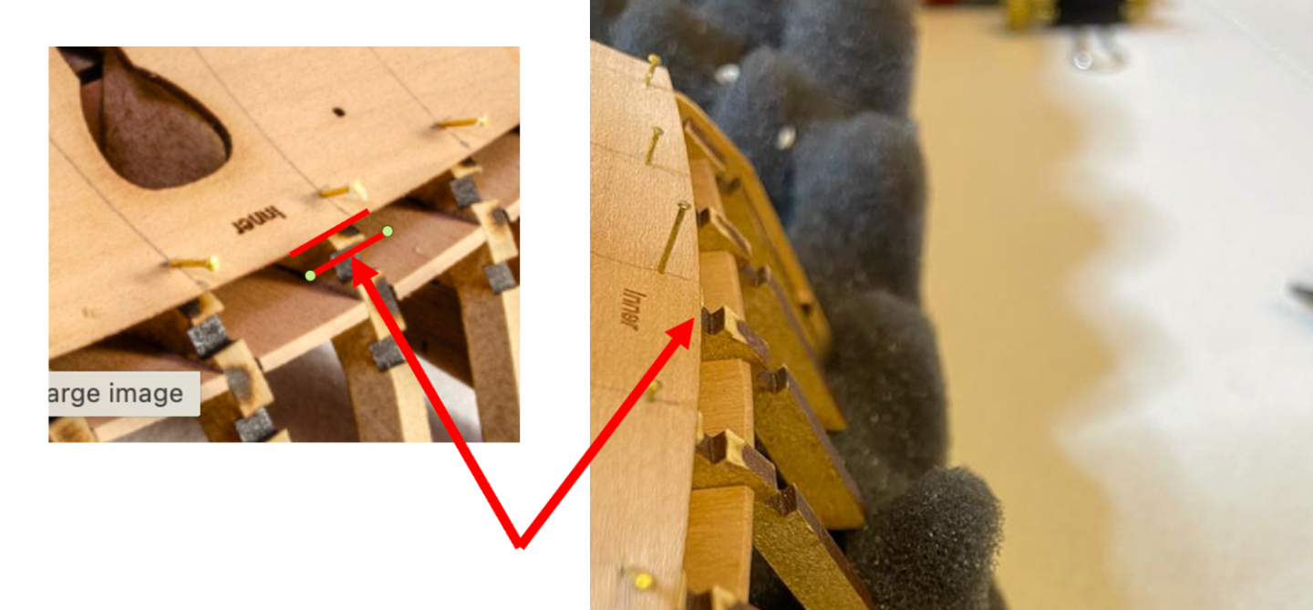
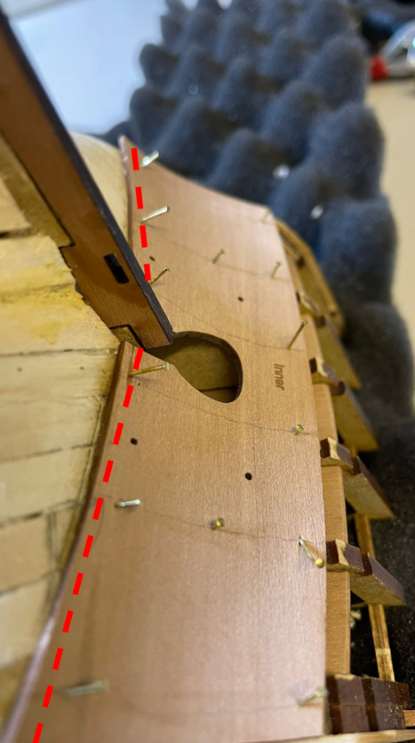
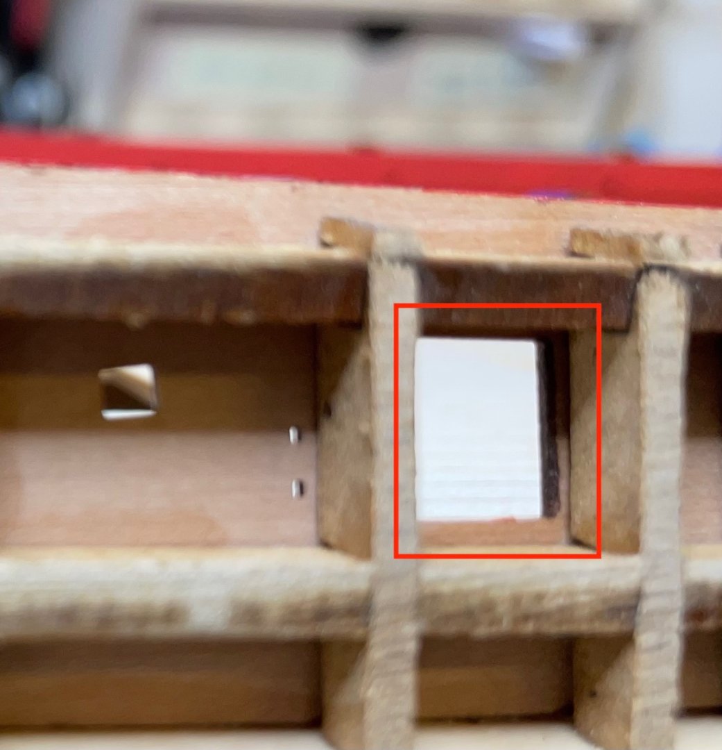
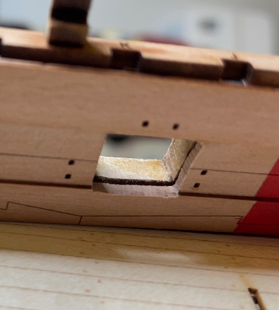
Jesus where did I go wrong? Here is a photo from another angle (mine is on the right). I was focusing on getting the top edge of the inner stern counter at the same height as the bottom of the stern timber slots and didn't really watch what's going on at the rudder post side (lower side). So, in yours it is about 2mm below the bottom of the timber slots, and therefore I raised it 2 mm making it at the same level as the bottom of the timber slots. But I can't explain why it it goes below the rudder post level on the other edge. Maybe I shall just trim the stern counter from the lower edge and make it level with the rudder post. It is very firmly glued in place now, I could do more harm trying to remove and reposition it. After that I could try to rectify the situation when installing the outer counter pattern.
- 426 replies
-
- 2
-
-
- Vanguard Models
- Sphinx
- (and 1 more)
-
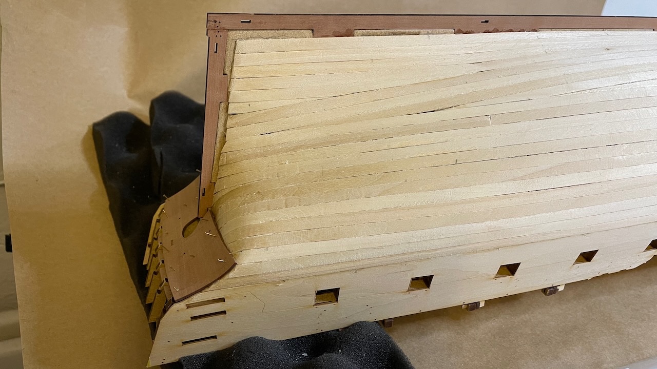
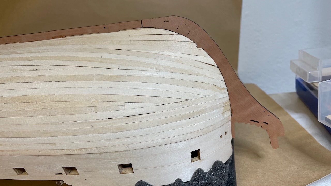
Photo 195-197: Inner stern counter in place, repositioned slightly higher than the photo in the manual as instructed. You see also prow-, keel- and rudder patterns installed.
- 426 replies
-
- 3
-
-
- Vanguard Models
- Sphinx
- (and 1 more)
-
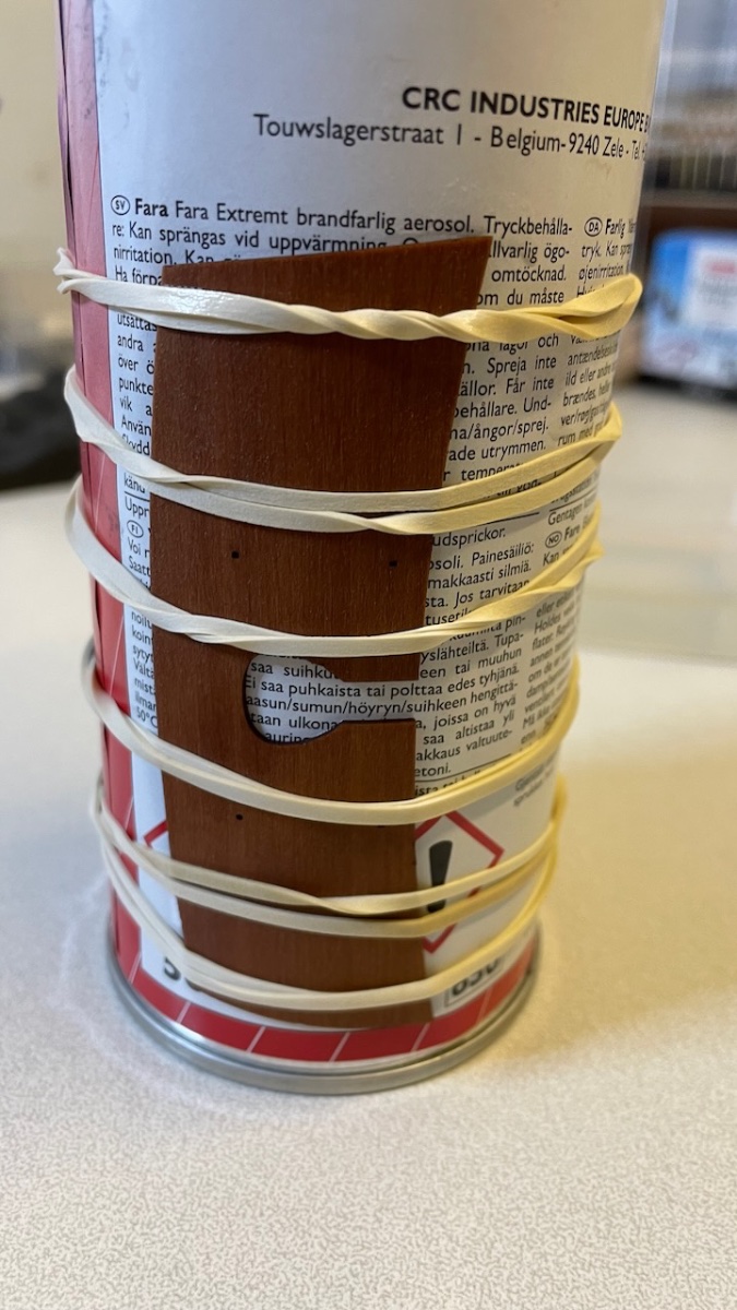
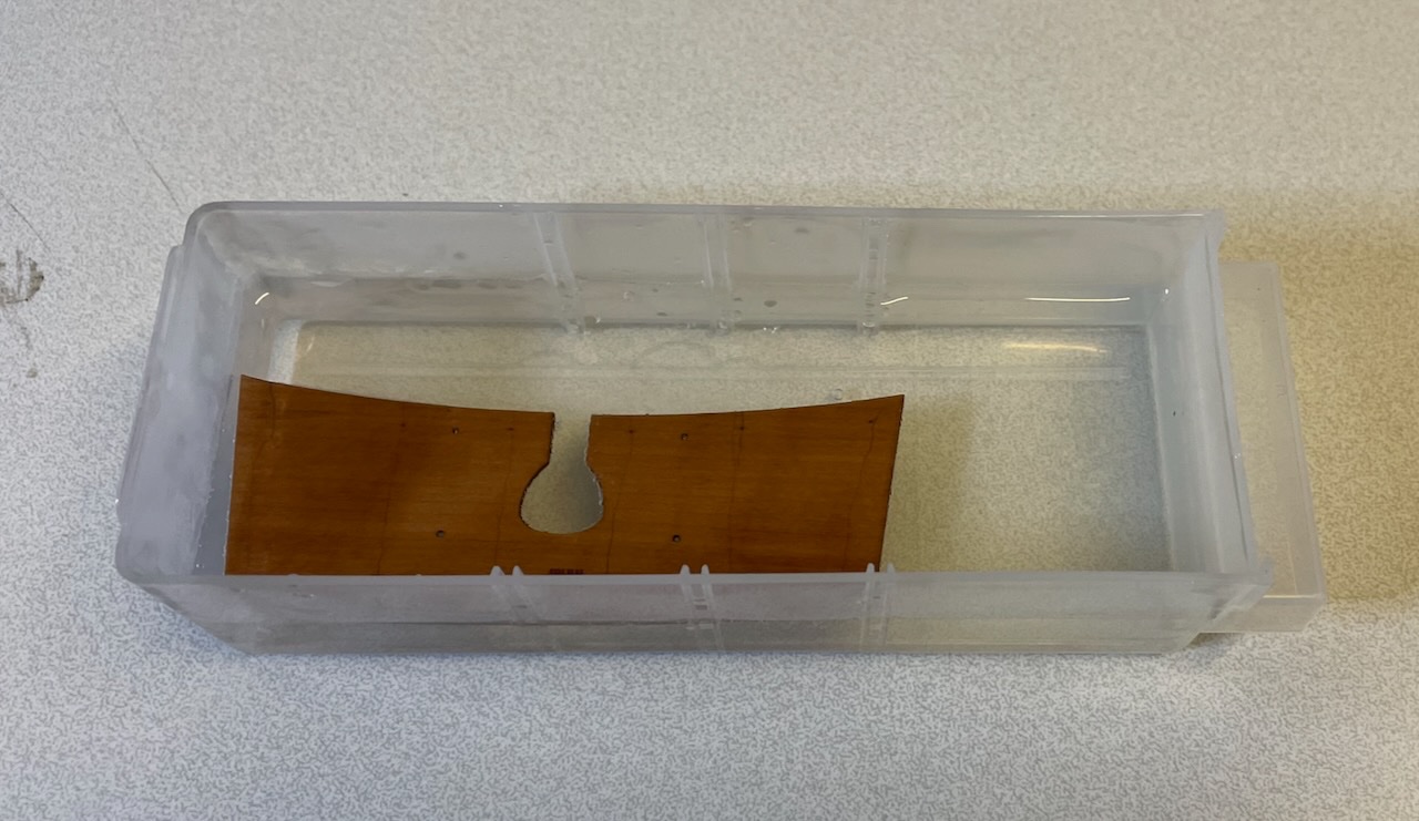
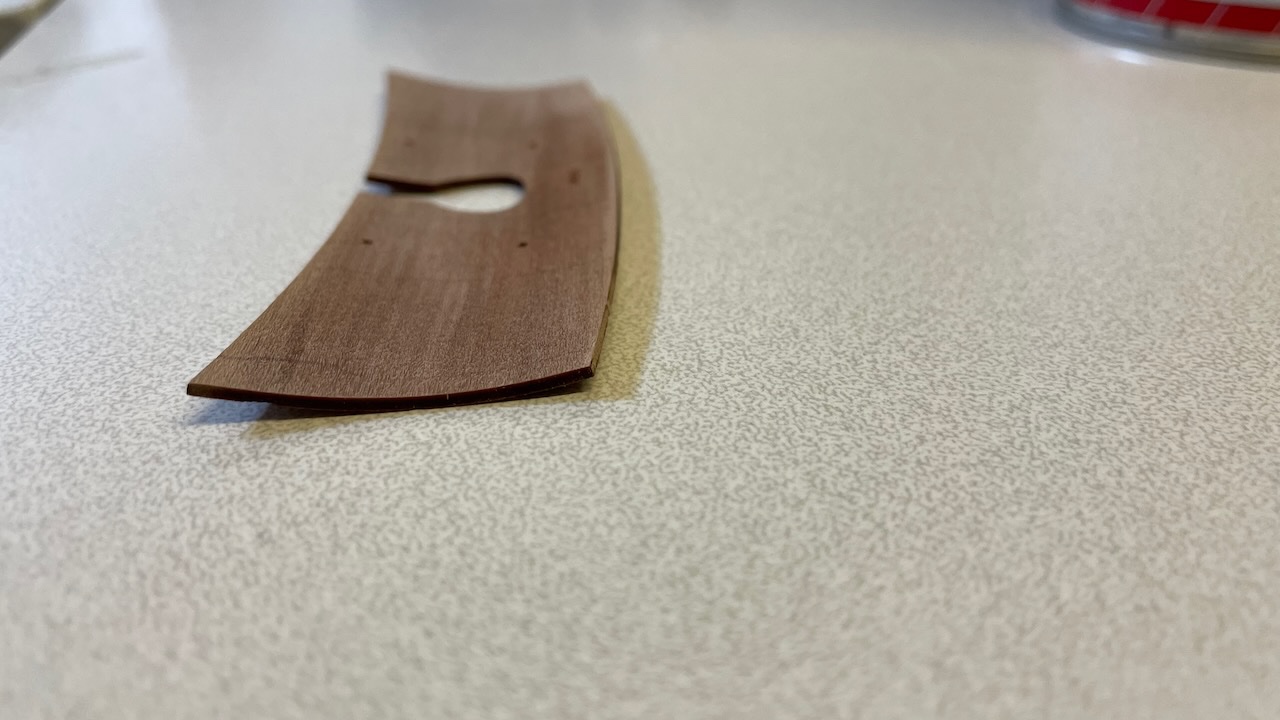
Photo 192: Inner stern counter soaking in hot water to curve. Photo 193: Wrapped around a spray can, secured with rubber until dry. Photo 194: Nicely curved. Still waiting a bit until it is totally dry.

- 426 replies
-
- 3
-
-
- Vanguard Models
- Sphinx
- (and 1 more)
-
Photo 191: After scraping I sanded with 80 grit and finally with 120 grit paper. The photo may not tell but it feels good enough to the hand for second planking.
- 426 replies
-
- 2
-
-
- Vanguard Models
- Sphinx
- (and 1 more)
-
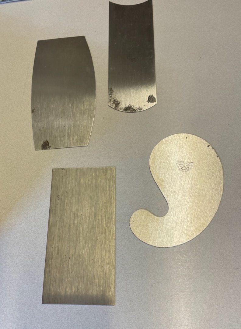
BUILD DAY 22: 3 hours / Total 42 hours. Today was about sanding first planking and installing stern counter, and prow- keel- and rudder patterns. Photo 189: First I used these scrapers to level the planks as much as possible as well as get rid of any hard glue particles. The various contours make it easy to scrape nicely. Photo 190: Now the surface looks more ready for sanding.
- 426 replies
-
- 2
-
-
- Vanguard Models
- Sphinx
- (and 1 more)
-
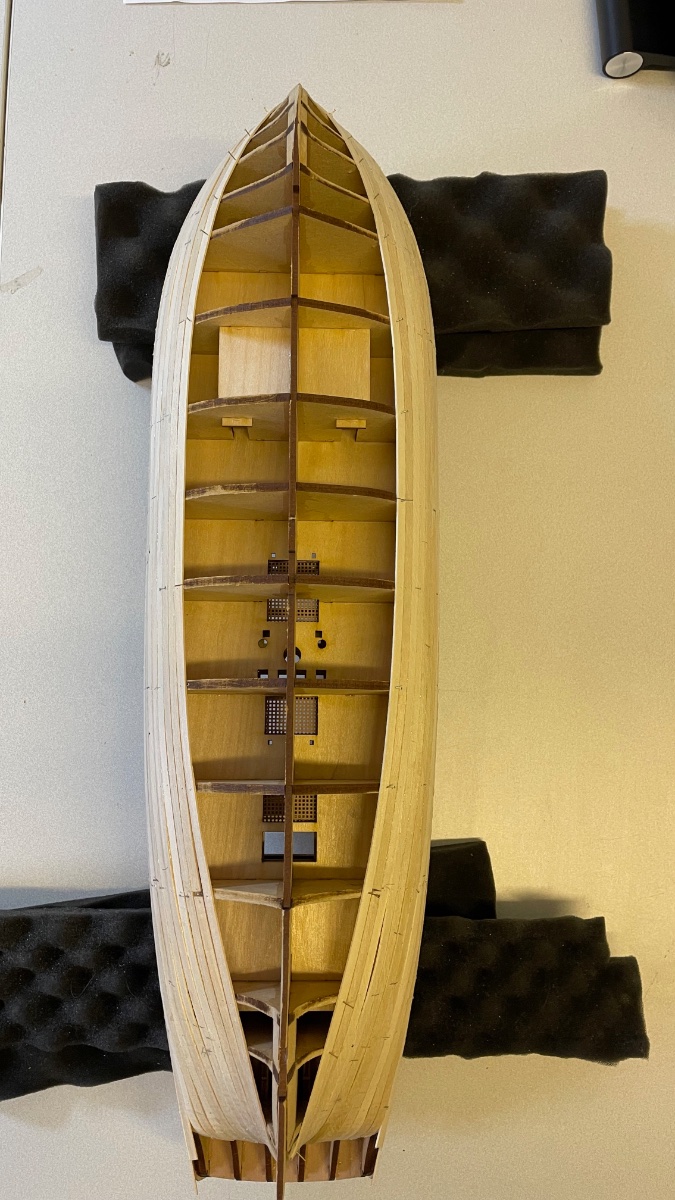
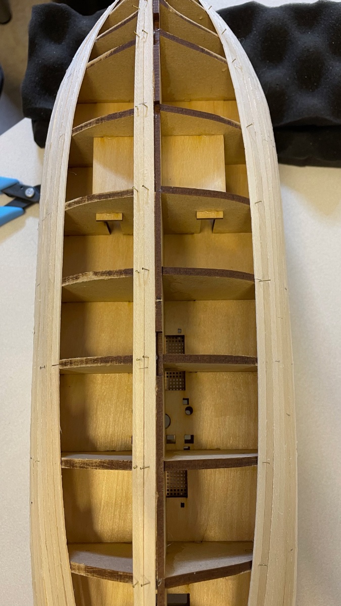
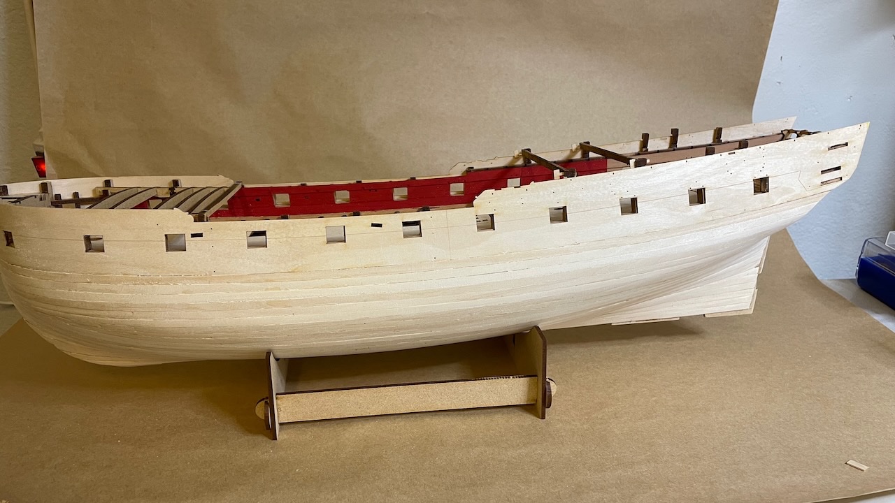
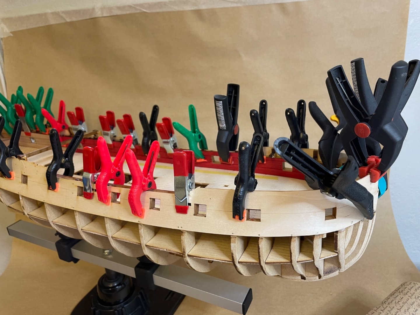
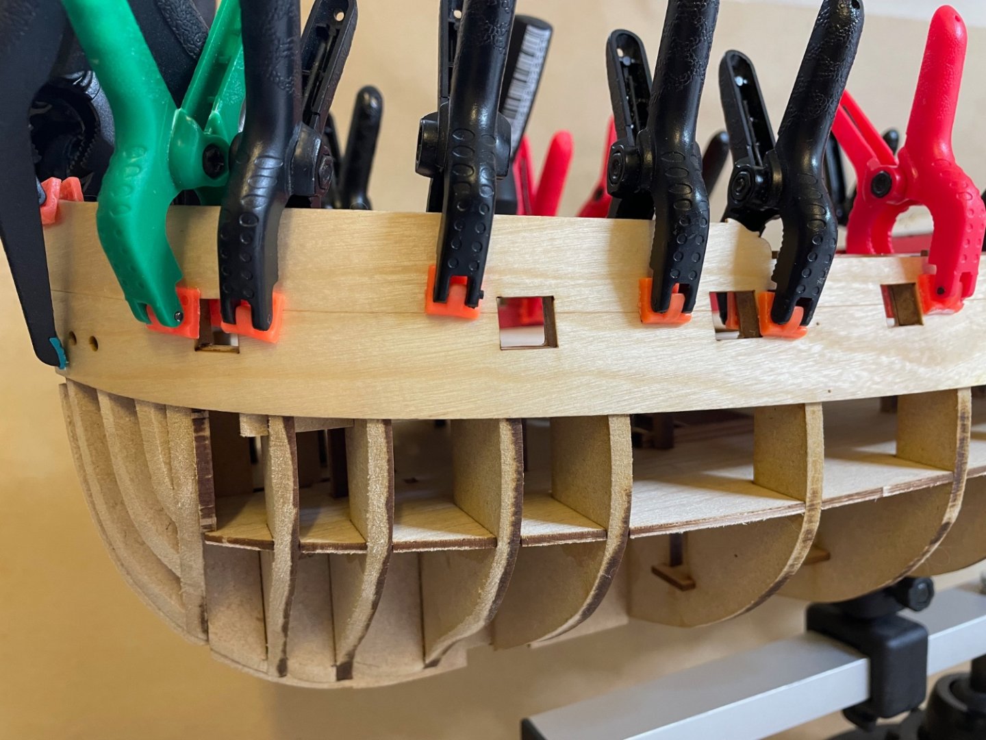
BUILD DAYS 15-21: 15 hours / Total: 39 hours Photos 187-188: First layer of planking is now complete. I have logged roughly 7 build days and a total 15 hours for the whole first planking. Sanding work and small fillings (if I find necessary) is next. As I was not careful and had oversanded the bow component earlier, I adjusted the bow curve by sanding it to fit the curvature of the Prow Pattern (#445). In the second photo, you can see it has a nice dry fit. I am satisfied with it at the moment, as there will still be the second planking, which will give further chance to cover any remaining imperfections.
- 426 replies
-
- 3
-
-
- Vanguard Models
- Sphinx
- (and 1 more)
-
I would never imagine there would be cannons right inside the command and control room with all the furniture and neat floor and stuff. Did they really fire them? Amazing.
- 488 replies
-
- 6
-
-
- Indefatigable
- Vanguard Models
- (and 1 more)
-
Photos 183-186: Some more progress this weekend. After 13 rows of planking, the strips would start to overlap on the previous one quite much so I decided to continue from the bottom. Now around 5-6 rows left to complete the first planking.


- 426 replies
-
- 5
-
-
- Vanguard Models
- Sphinx
- (and 1 more)
-
As autumn comes, busy times at work and in general with life, I can rarely find any time to continue with planking. But still, first planking is proceeding. Since this task goes rather scattered with sometimes only one hour in a day and nothing several weeks, it does not make much sense to count build days and hours at this point. So, I will make a total estimate of time it took to complete the first planking, when it is complete. As I wrote earlier it takes about half an hour to complete one row of stripes on both sides, hence, the total time will be roughly (number of plank rows) / 2 hours Here are some photos to show the progress. Overall no surprise, going pretty much like in the instruction manual. You'll notice the planking on the bow not as it is supposed to be. This is because I had screwed up the bow structure by oversanding it, if you read my earlier posts. Right now I make it so that the strips meet in the bow. I will then sand them to the shape to fit the Prow Outer Patterns. Photos 180-182:

- 426 replies
-
- 7
-
-
- Vanguard Models
- Sphinx
- (and 1 more)
-
BUILD DAY 14: 2 hours / Total: 24 hours Back to build after 2 weeks of vacation in Kusadasi, Turkey at the Aegean Sea coast. The first 3 rows of planking went just like in the instructions, quite straightforward with no need of tapering. So far it takes about half an hour to plank one strip per side (i.e. 2 strips). I am sure with my speed it will take longer than this in the coming planks where I will need to do the tapering. Photo 178: This was the only bending I had to do for the first 3 rows. Photos 179-180: Overall the strips contact the bulkheads quite nicely. I applied nail only in some locations.


- 426 replies
-
- 3
-
-
- Vanguard Models
- Sphinx
- (and 1 more)
-
If it occured to me before, I could have used them for Upper Hull Side Patterns, too, like you did. Instead I used nails.
- 426 replies
-
- 3
-
-
- Vanguard Models
- Sphinx
- (and 1 more)
-
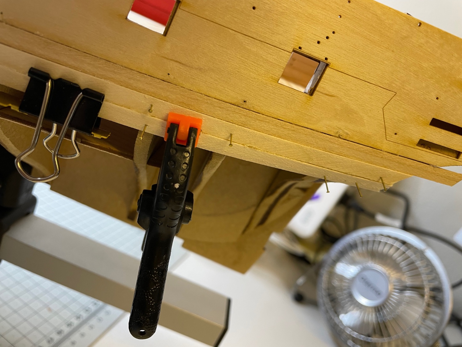
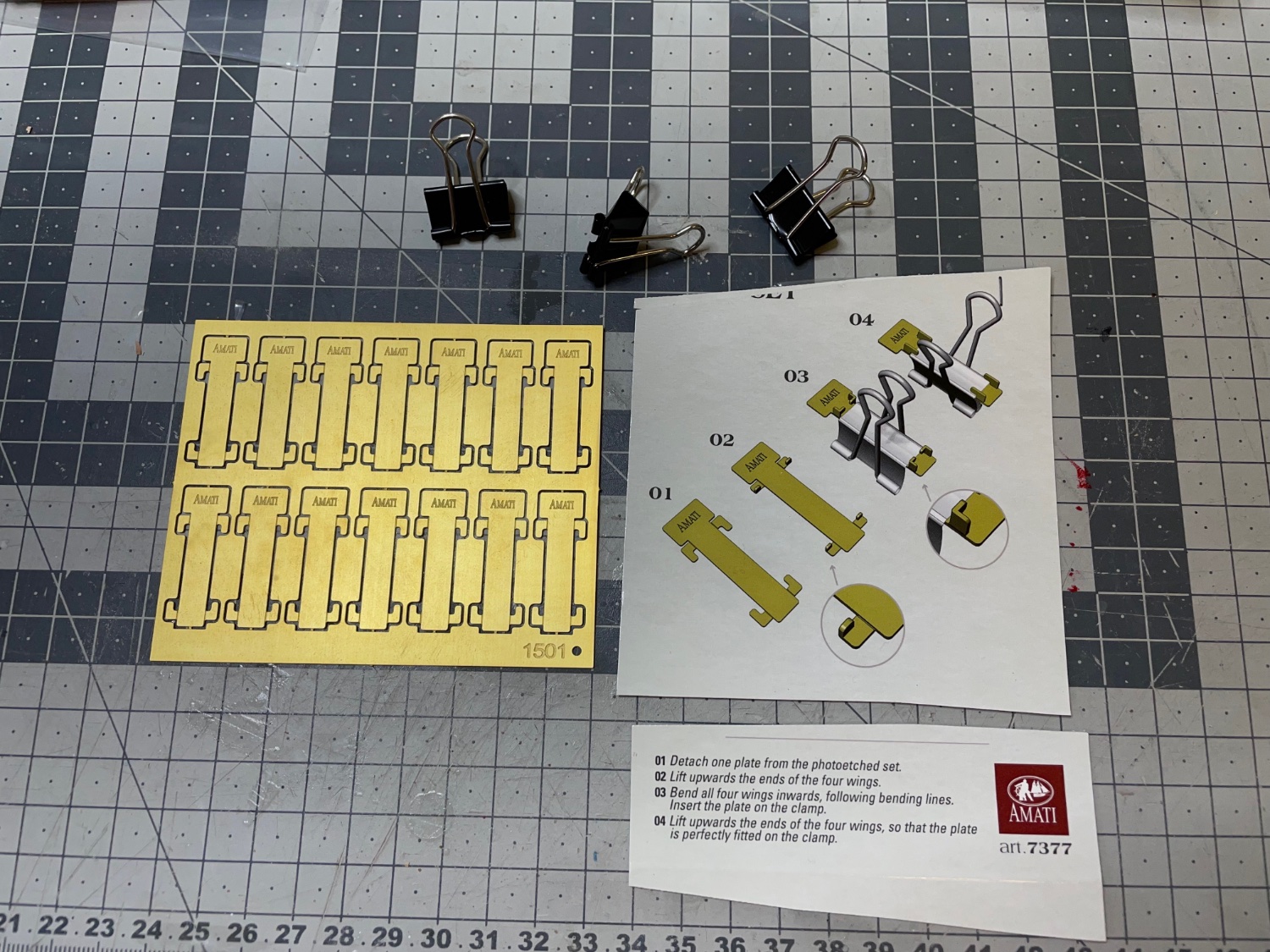
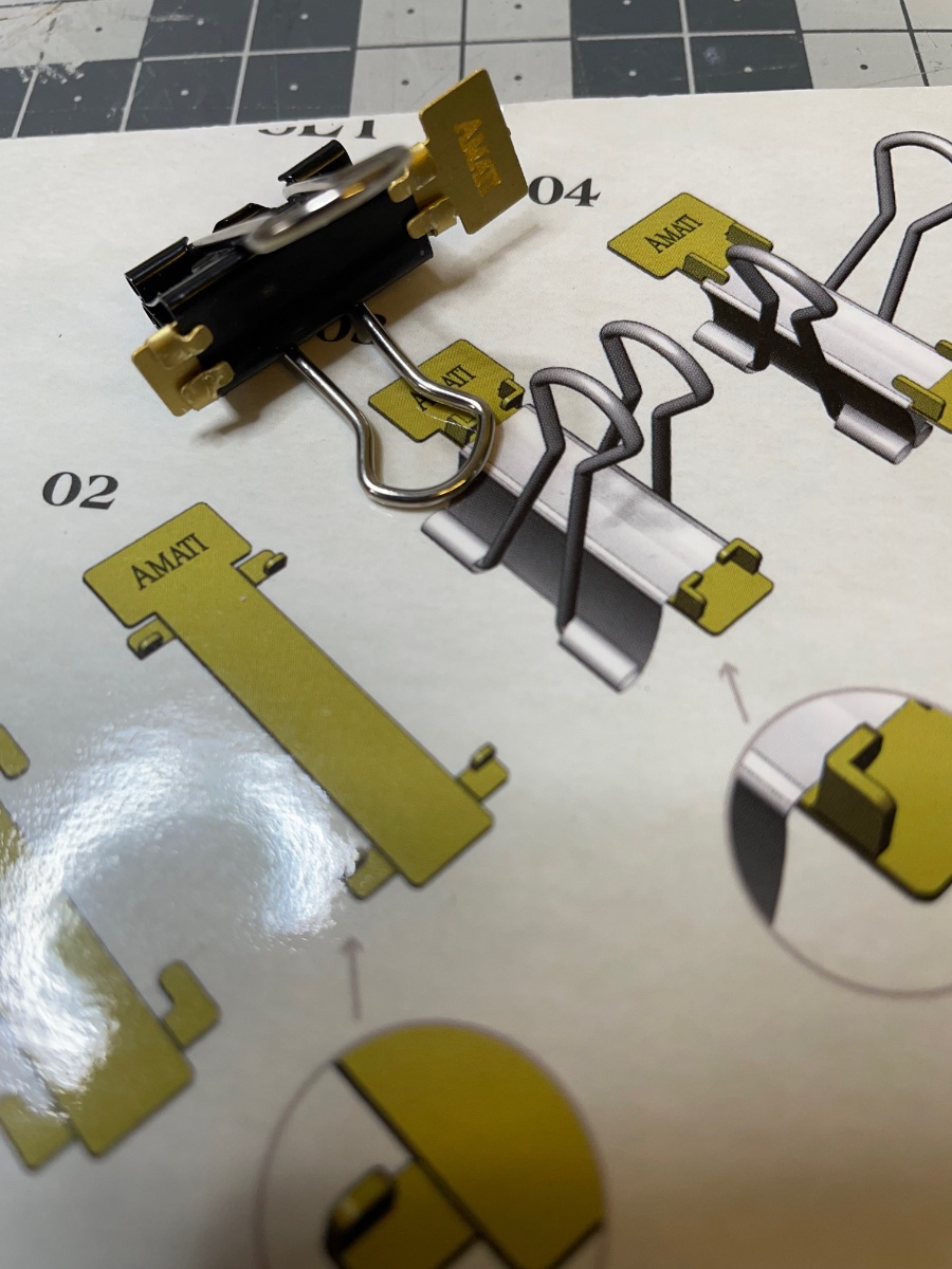
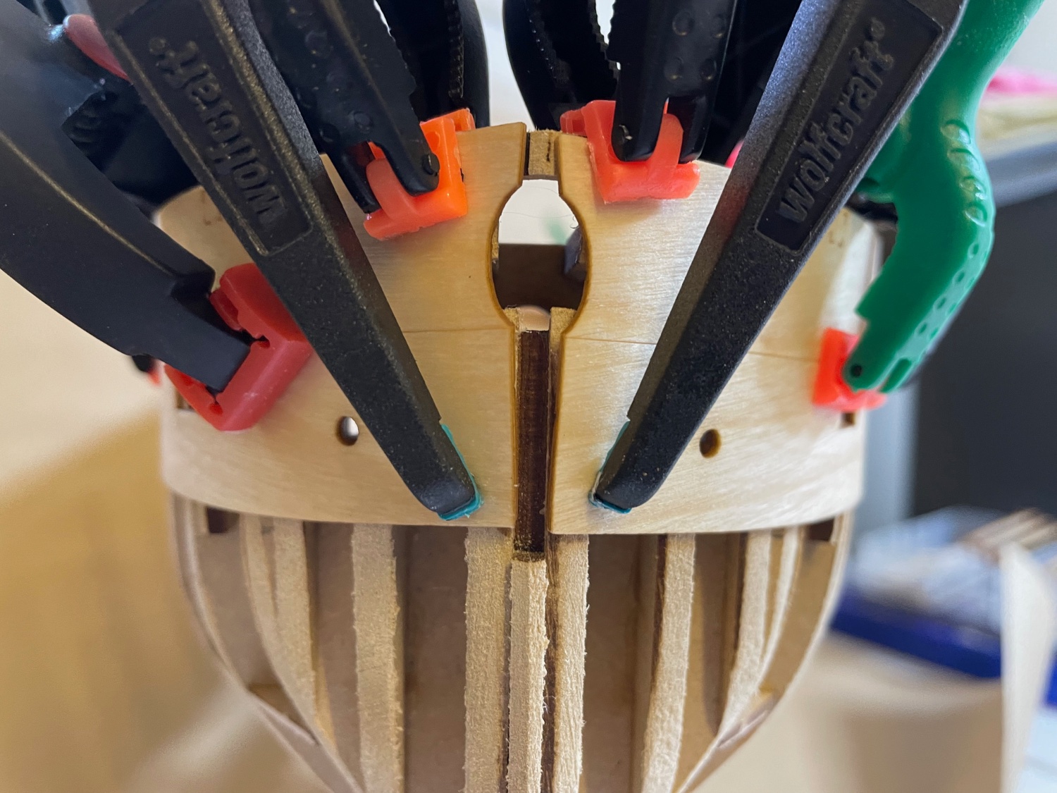
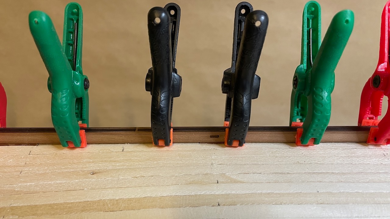
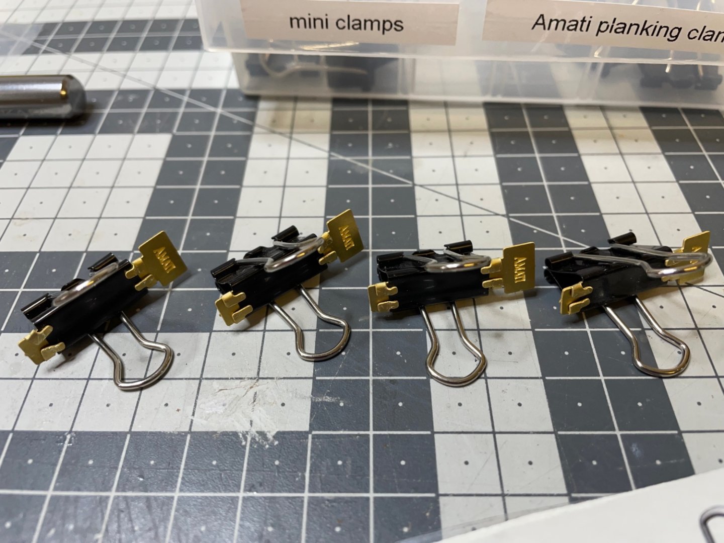
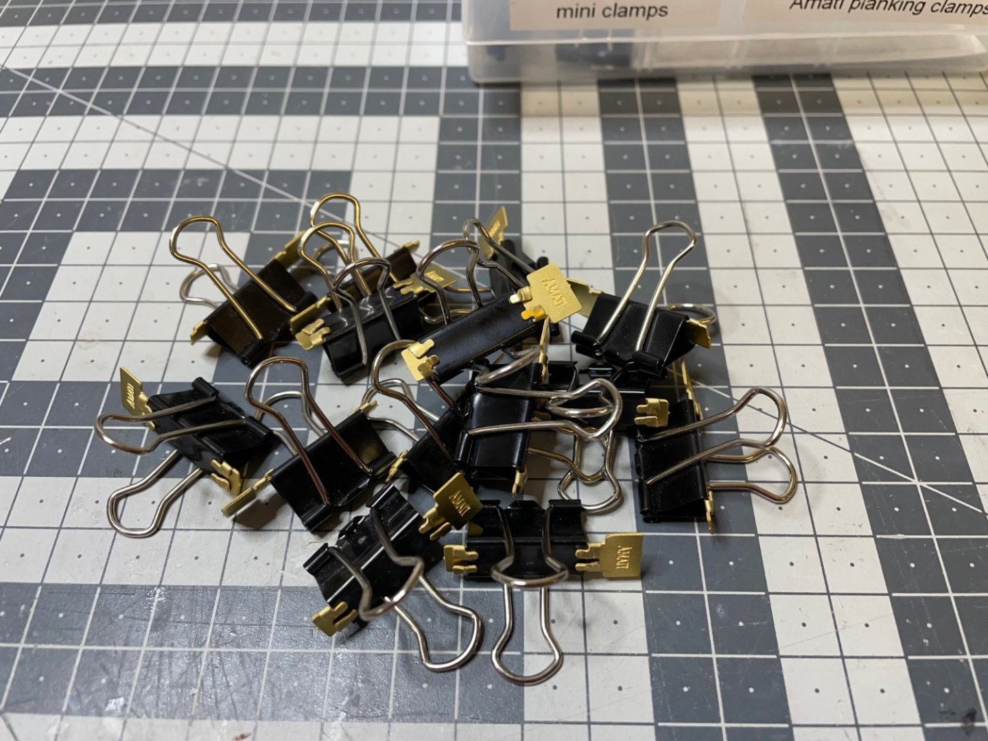
Photos 173-176: Well, while the glue is drying, I decided to get my hands on to these Amati planking clamps. I had bought them many years ago and had never used. I even forgot about them and when I saw them in Glenn's Sphinx build log, I thought I'll give them a try. It is a small project to prepare them:


- 426 replies
-
- 5
-
-
- Vanguard Models
- Sphinx
- (and 1 more)
-
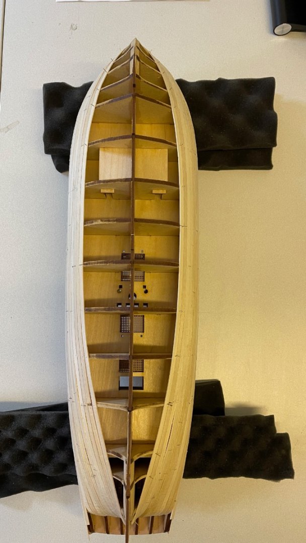
BUILD DAY 12-13: 2 hours / Total: 22 hours Photo 167: The parts dried enough overnight. This is one of them to show that the shape remains after removing. Photo 168: Brushing diluted wood glue, as recommended in the instructions. Here I mixed it with a bit less water, thus let it a bit thicker, compared to for example when I brushed in to the joints bulkheads, since in this case I don't need it to penetrate into any joints. This way it also won't run and leak. It is enough that it gives you time to make adjustments before it cures. Photos 169-171: Carefully glued them in their positions. My main reference was to align the bow and then go on aligning with the gun port openings. You see in the last photo I used pins to ensure contact in a few spots where there was a gap at bottom edge with the bulkheads. Photo 172: Waiting for the glue to dry. I am not starting planking today so I give them the whole overnight to dry properly. As you see I also placed the jigs into place, so the hull shape maintains correct while the glue dries. I wanted to do this because some bulkhead ears move slightly inwards/outwards when I use clamps. The jigs keep them in position.


- 426 replies
-
- 4
-
-
- Vanguard Models
- Sphinx
- (and 1 more)
-
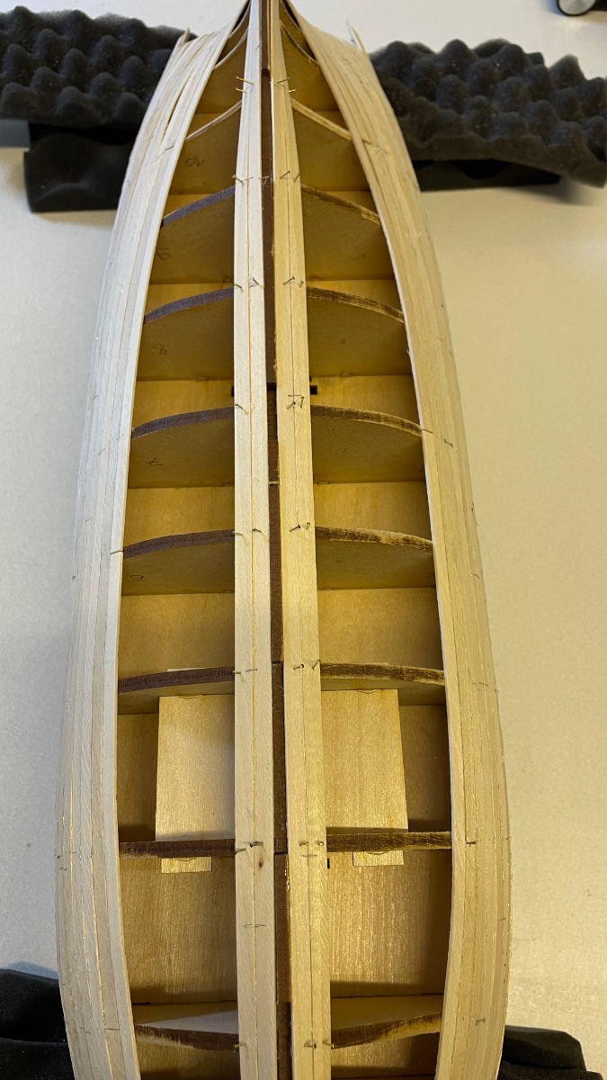
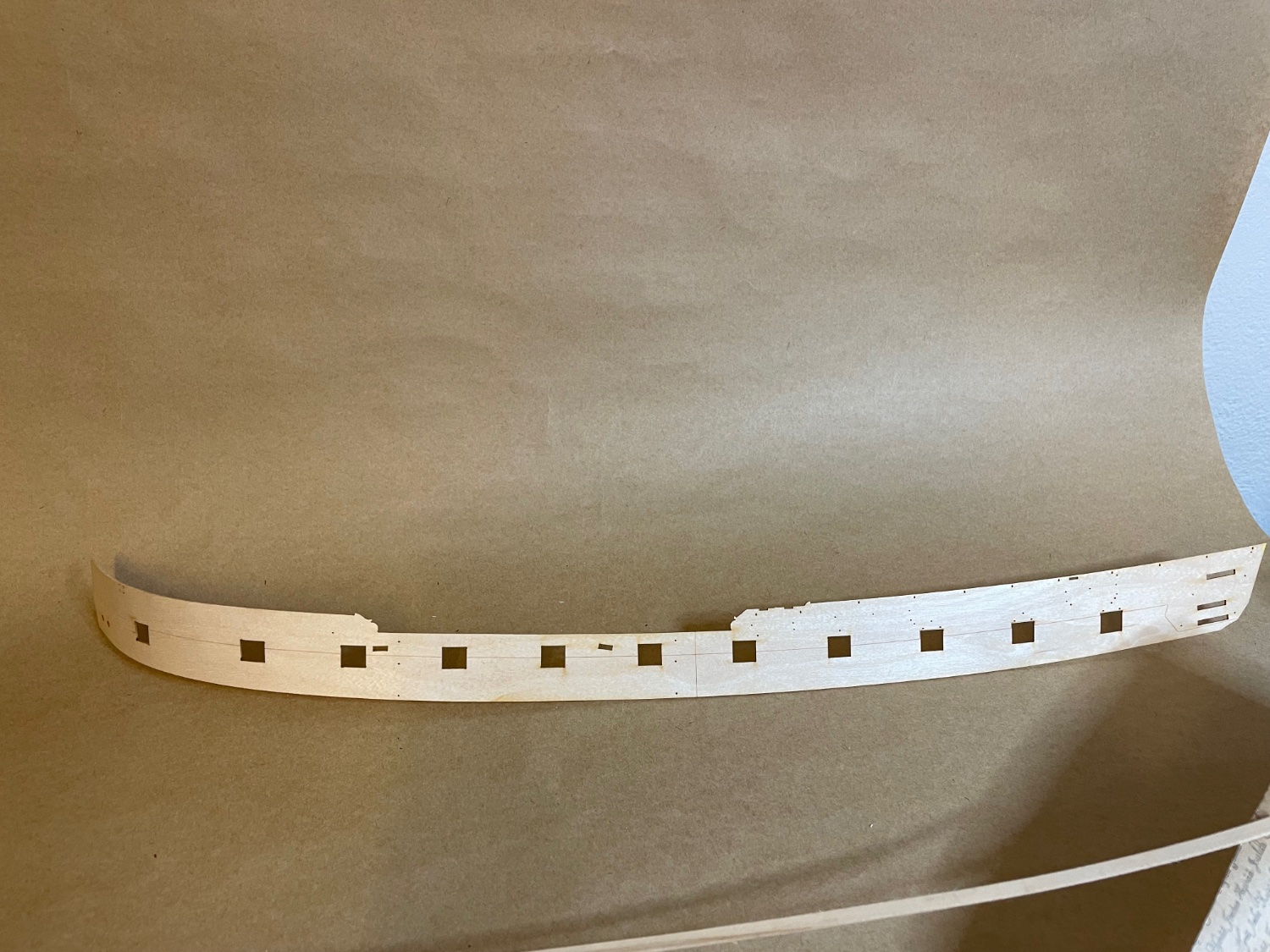
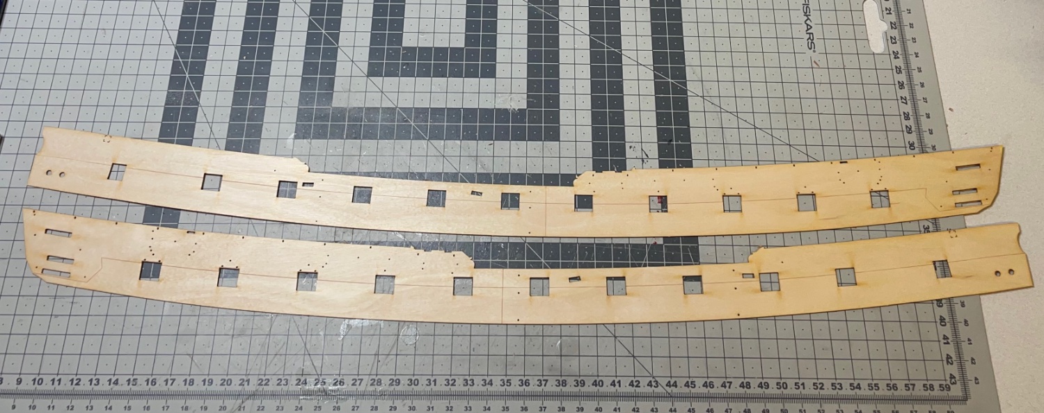
Photos 164-166: Upper Hull Side Patterns dry fit (or wet fit to be correct ) waiting to dry overnight. If you look at the photo taken from above, they fit almost airtight to the hull, making me overall satisfied with my hull construction... except for that little over-fairing at central keel at the prow discussed in my recent post.


- 426 replies
-
- 5
-
-
- Vanguard Models
- Sphinx
- (and 1 more)
-
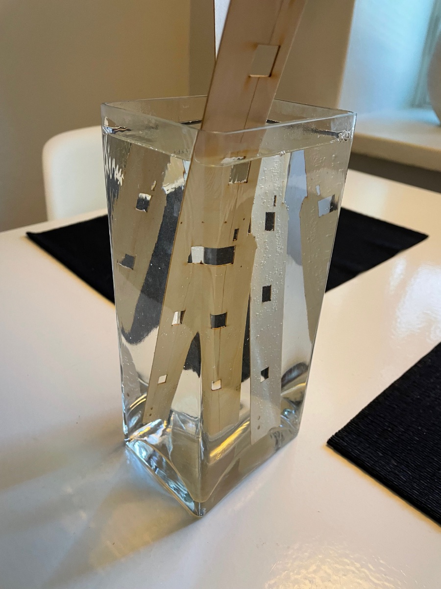
Photos 162-163: In the mean time the Upper Hull Side Patterns are being soaked in hot water in a flower vase deep enough I found at home.


- 426 replies
-
- 4
-
-
- Vanguard Models
- Sphinx
- (and 1 more)
-
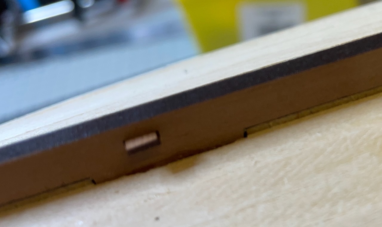
Build day 12: 1 hour / Total: 21 hours Thank you Chris for this short chat and I finally decided to trim the openings. Overall I used the x-acto and two different sizes of files, it went quite alright for the total of 20 gun ports. It took about an hour in total, at a few minutes per opening. Photos 159-161: Here are some before and after photos, they do not necessarily belong the same gun port opening.

- 426 replies
-
- 5
-
-
- Vanguard Models
- Sphinx
- (and 1 more)
-
Well, OK not a mathematical square but I meant that when I look at the gunport openings on the inner bulwarks from the deck side, they are perfectly laser cut and identical looking, though I understand that those cuts are made smaller than normal, to be trimmed later to the size of the MDF frames. I was just wondering if I would avoid trimming them from outside with a knife, would it cause a problem during construction later, other than visual. Maybe I am just being lazy.
- 426 replies
-
- 1
-
-
- Vanguard Models
- Sphinx
- (and 1 more)