HOLIDAY DONATION DRIVE - SUPPORT MSW - DO YOUR PART TO KEEP THIS GREAT FORUM GOING! (Only 20 donations so far - C'mon guys!)
×


aydingocer
-
Posts
916 -
Joined
-
Last visited
Content Type
Profiles
Forums
Gallery
Events
Everything posted by aydingocer
-
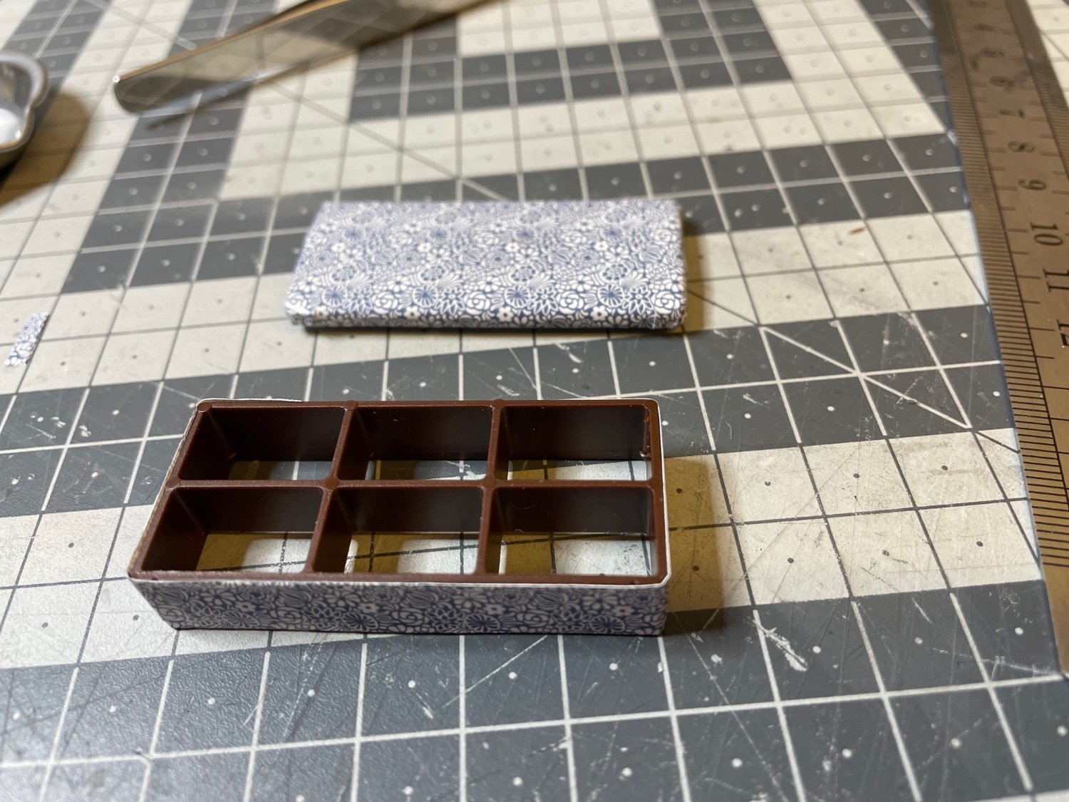
 Figure 244: Two sofas transformed into open beds. Looking cute. One of those moments that make me feel more like I am building a doll-house 🤣.
- 293 replies
-
- 12
-

-
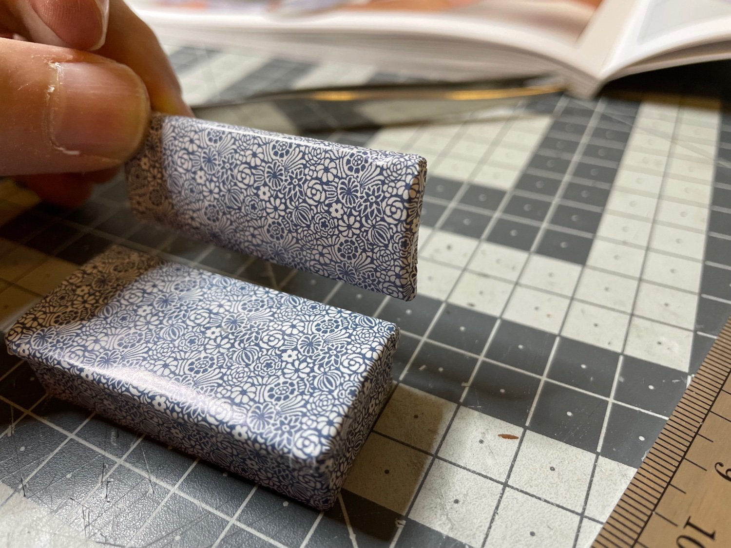
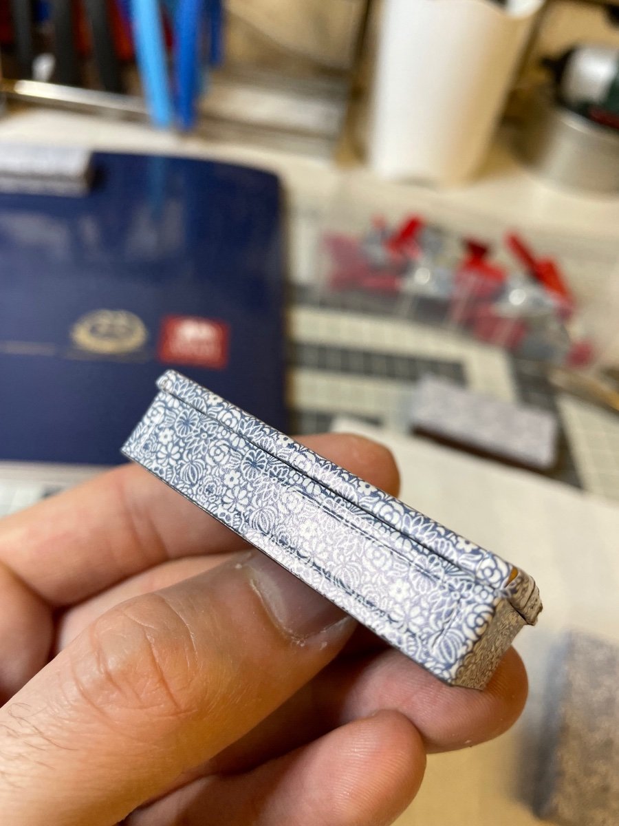
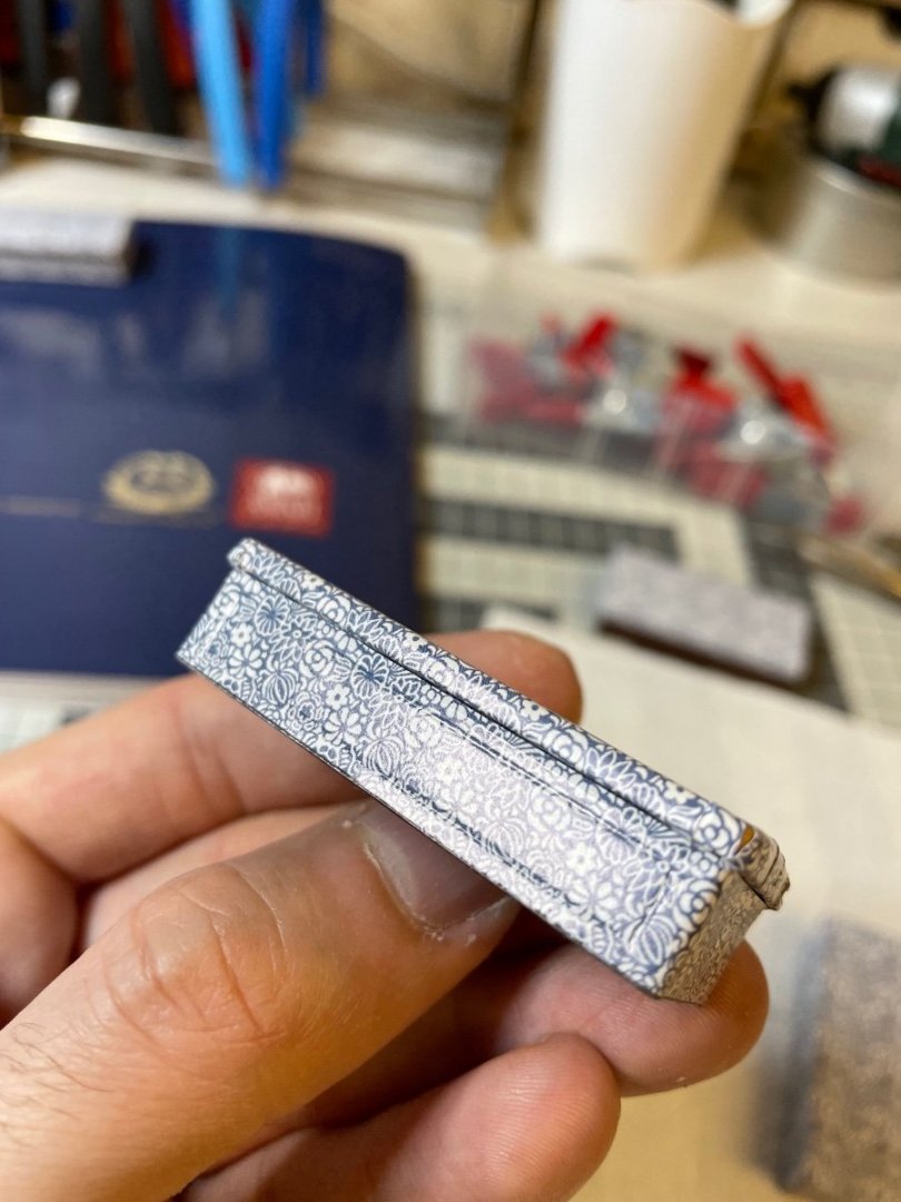
Figure 241-242: The bed structure. Again covered with paper. The same are used also for the two aforementioned open bed versions, which will come later. Figure 243: The front face of the bed structure has reactangular grooves. Note in the photo, I went over them with a toothpick to make them visible.

- 293 replies
-
- 11
-
-
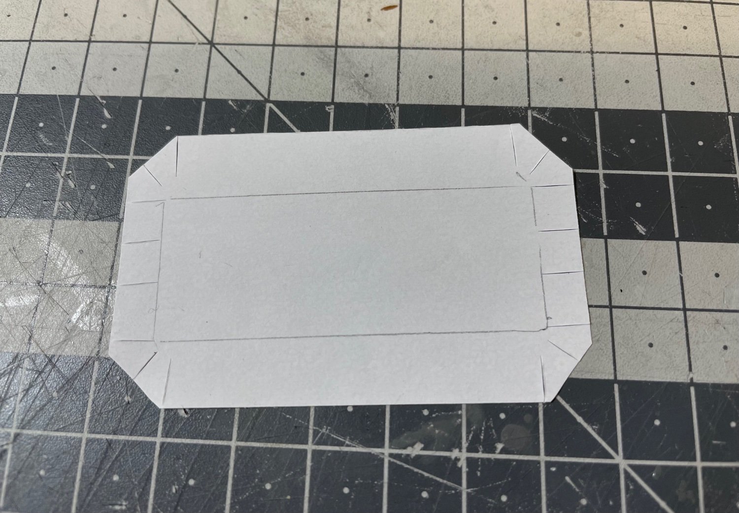
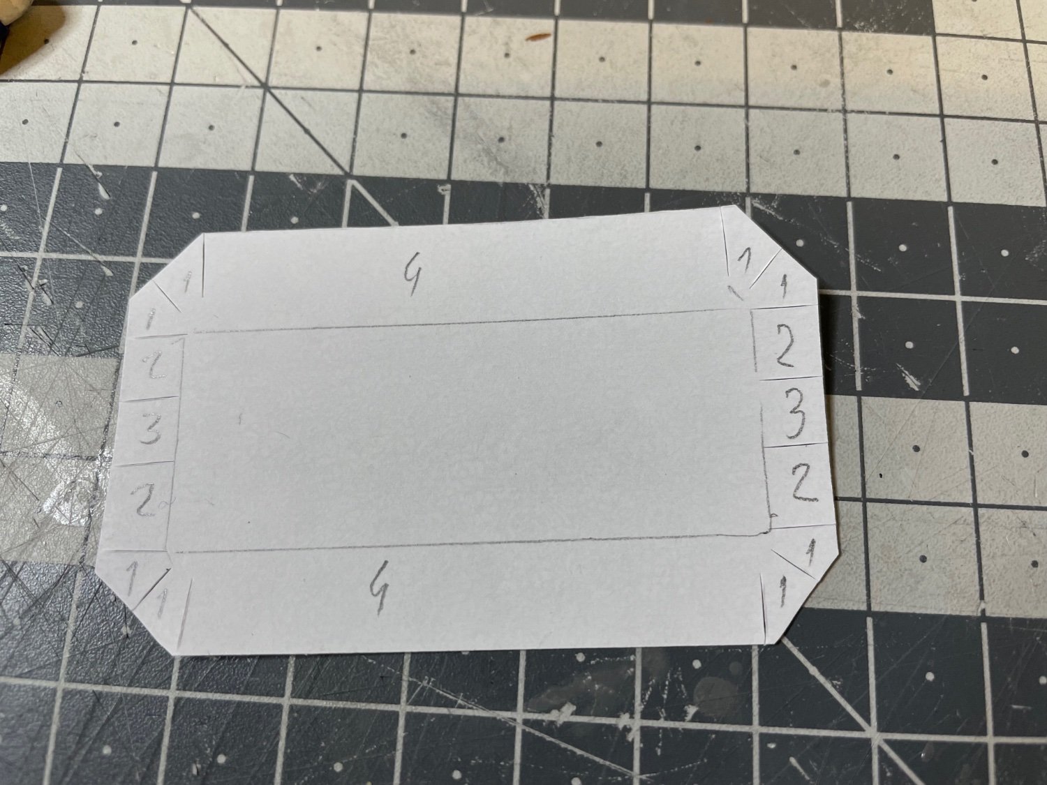
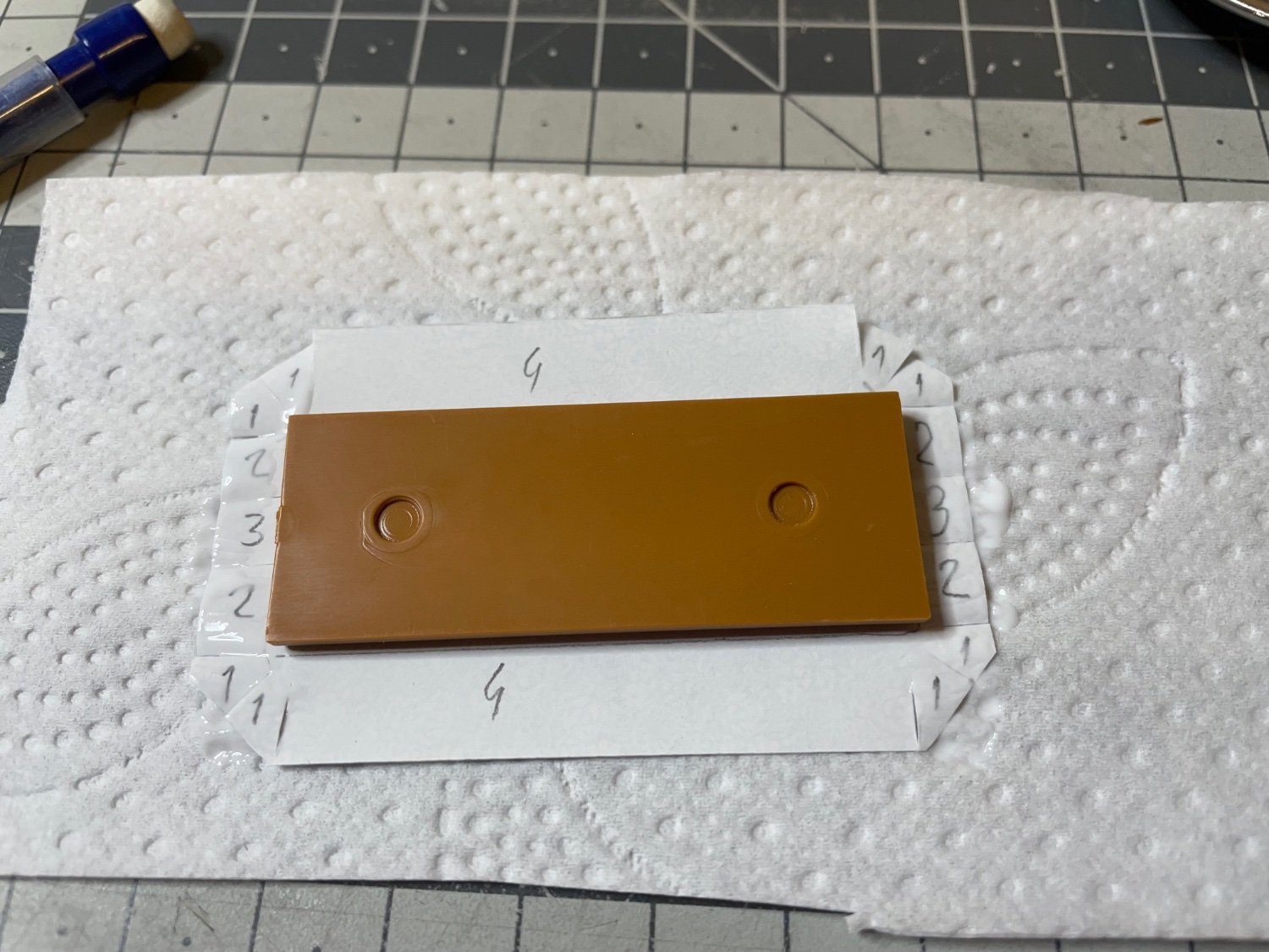
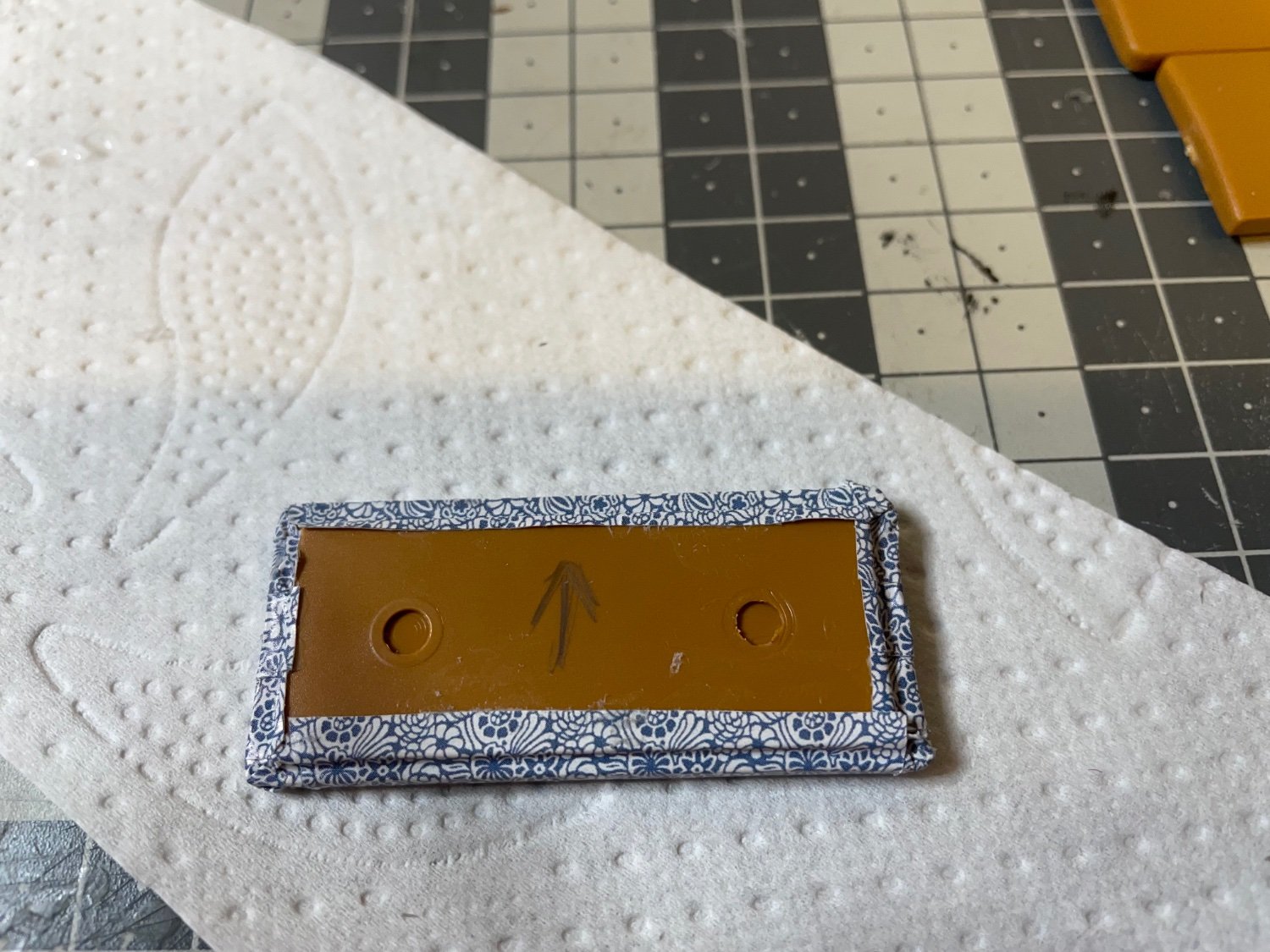
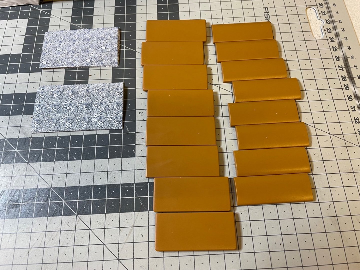
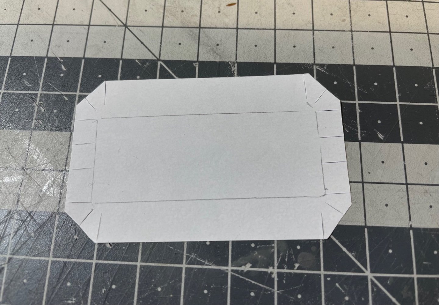
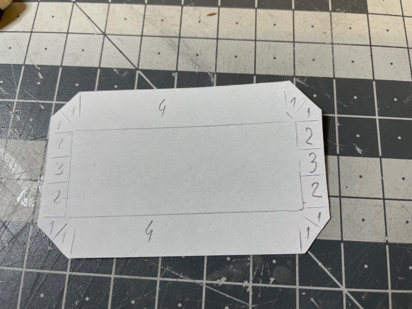
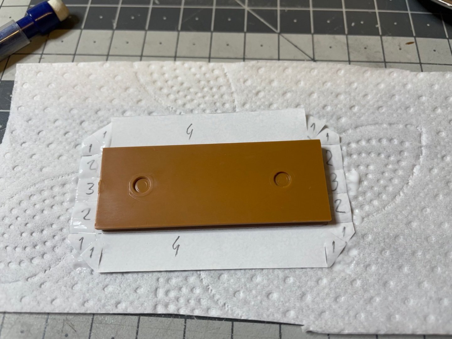
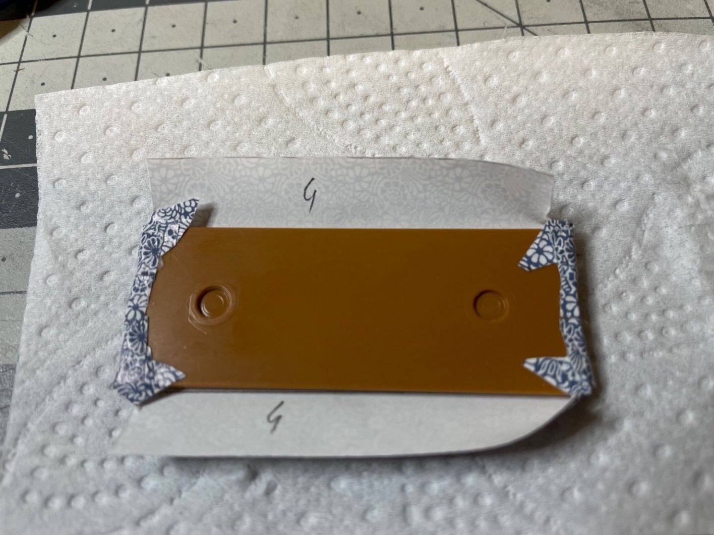
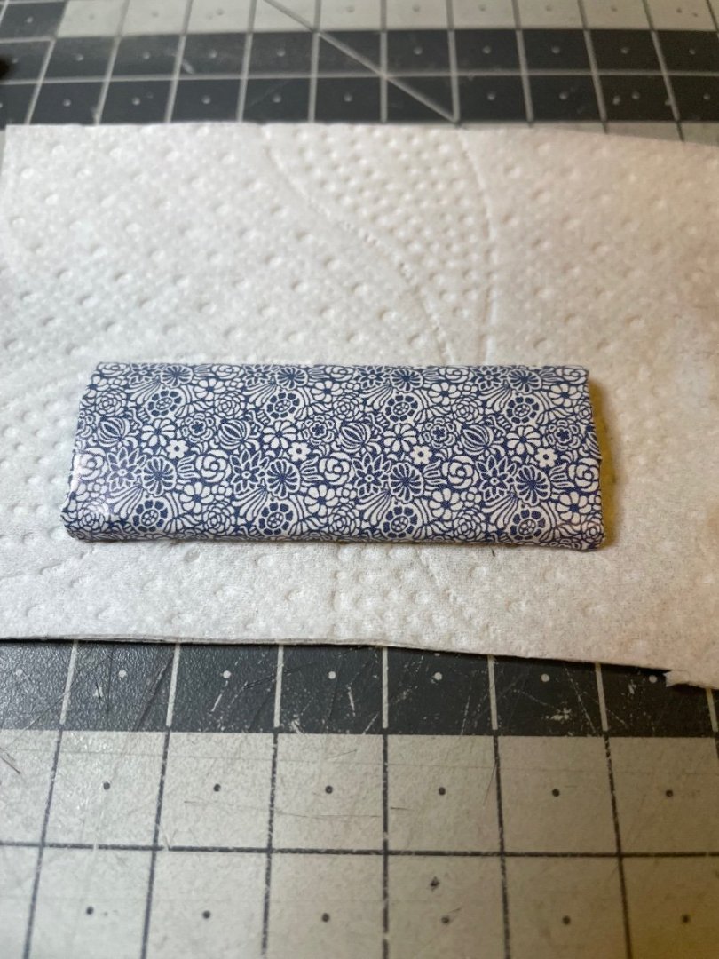
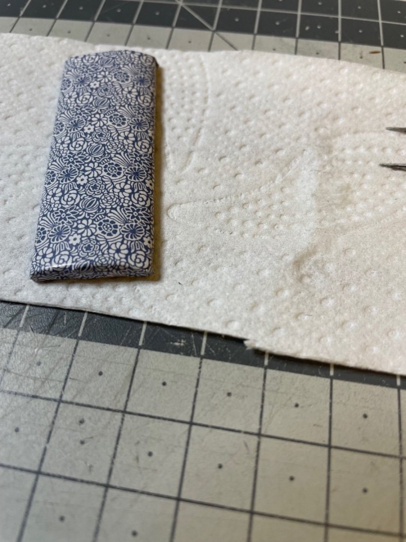
Divans with backrests. Figure 233: Naturally there are 10 divans, one per compartment. In this model, 8 of them are provided as daytime divan and 2 of them as transformed into beds. It is up to you in which compartments you place them. Figure 234: Even though the paper parts are rectangular, I trimmed the edges a bit in order to get the corner folds smoother. It also helps to mark the fold lines on the back side of the paper using a pencil. Figure 235: For a proper final shape, the paper will be folded in the order as below: 1-2-3-4 Figure 236-238: Photos showing the progress. This is the seat. Figure 239-240: Backrest. Exactly the same process as the seats. Note the long edge on the right side of the photo is slightly thicker than the one on the left side. That's the lumbar support, which should face down when installed on the wall. That's why I marked the back of it with an arrow, indicating the upward direction.

- 293 replies
-
- 10
-
-
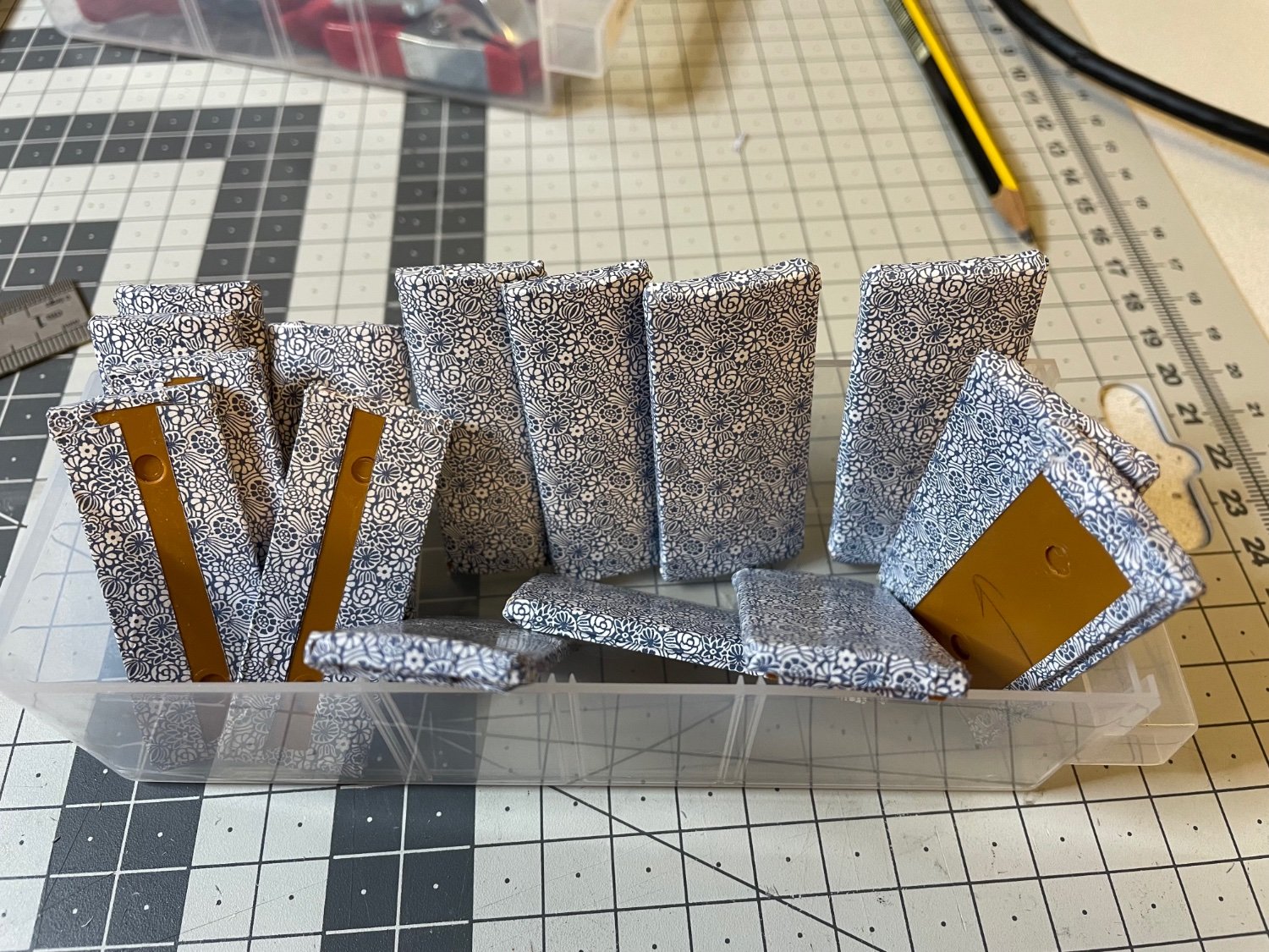
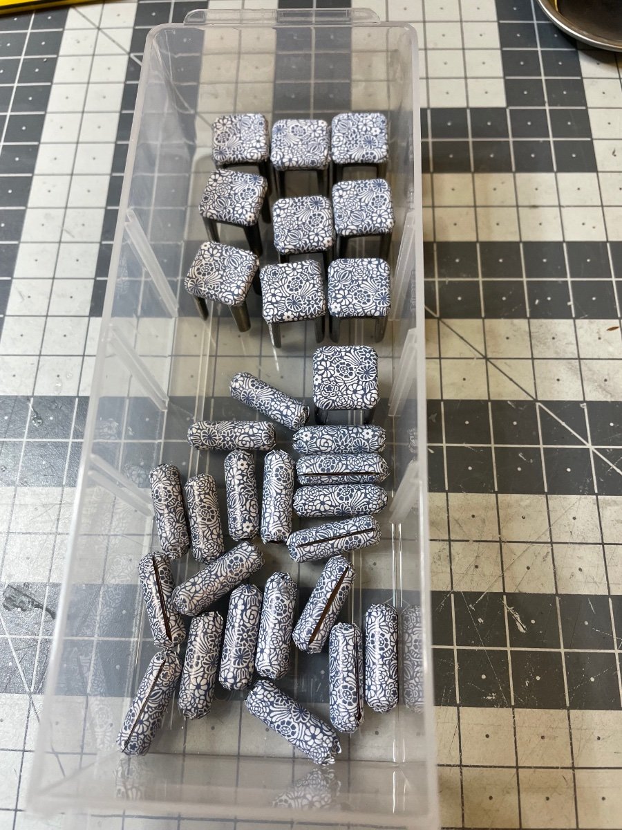
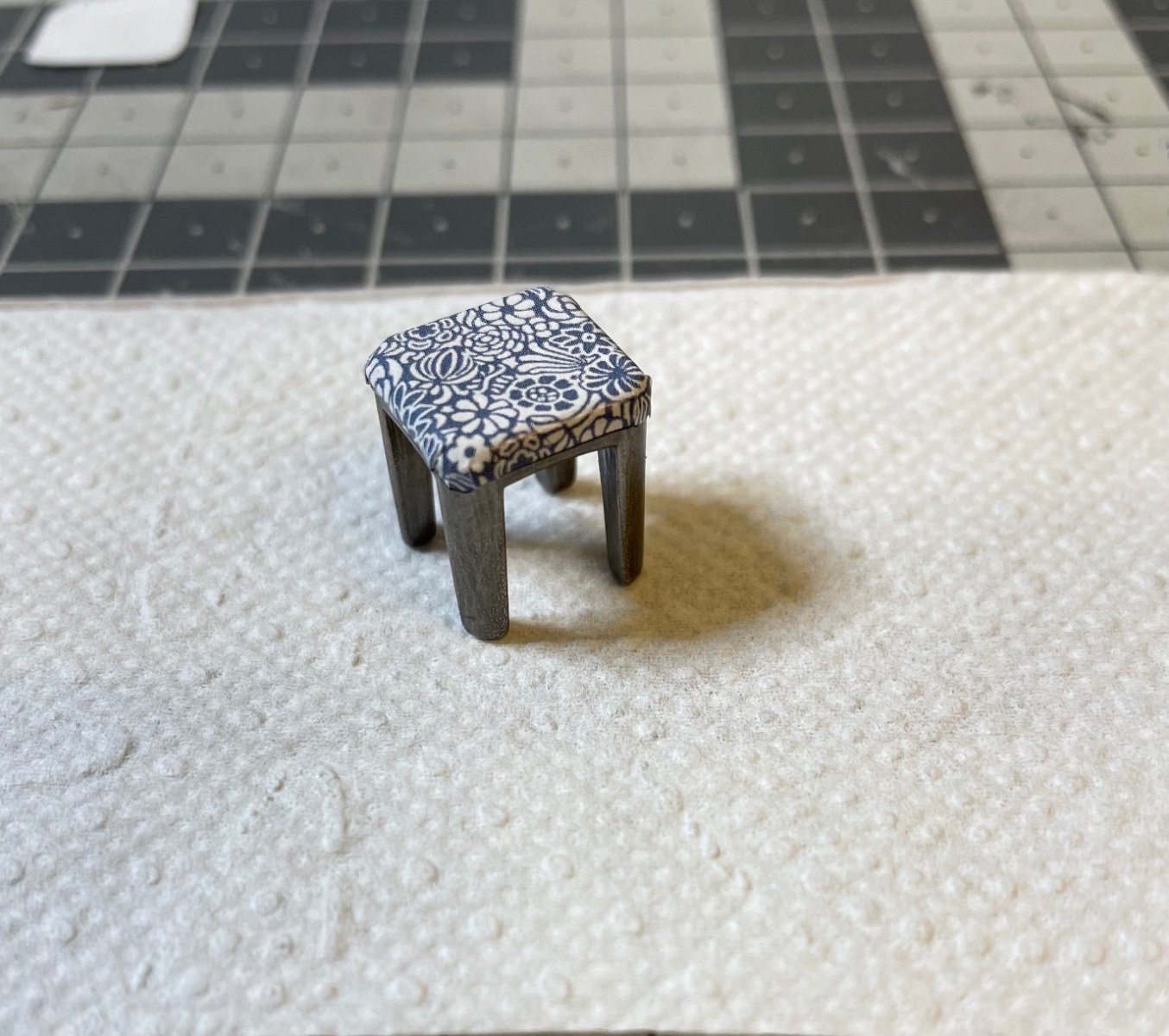
Figure 232: All the stools and armrests complete, waiting to be installed in place.

-
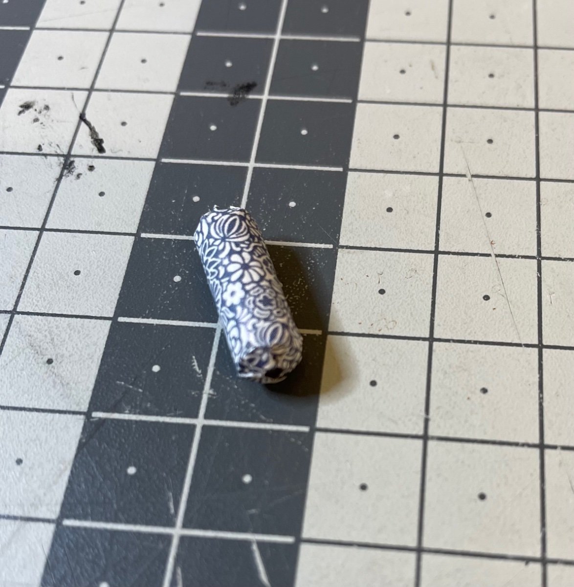
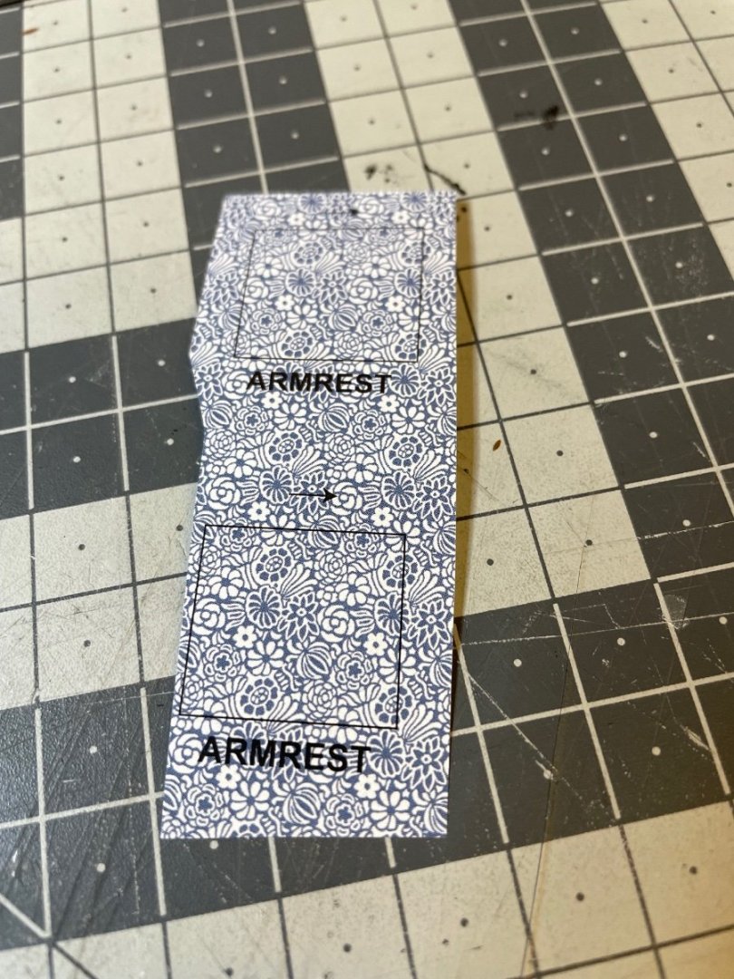
Construction of the armrests. Two per sofa, i.e. per compartment. Figure 229: Papers are labelled on the sheet. Figure 230: Plastic parts and papers ready. Note in the photo above (Figure 229), that the paper must be glued in the direction of the thin black arrow printed above the pieces. I transferred the arrows to the back of the papers to ensure a correct installation. Figure 231: First armrest ready. 19 to go.

-
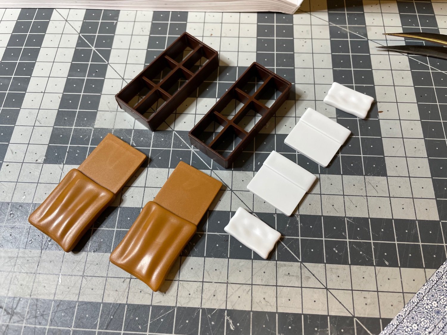
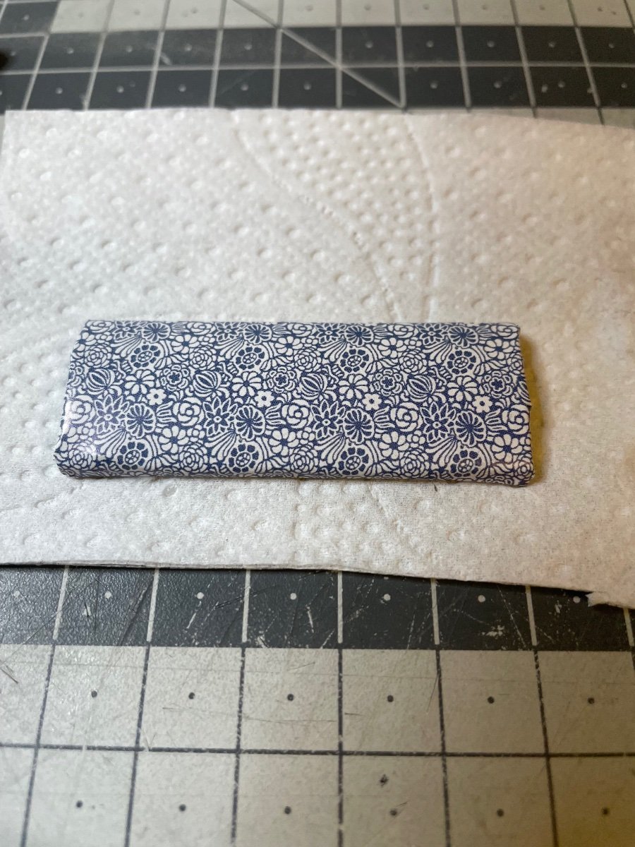
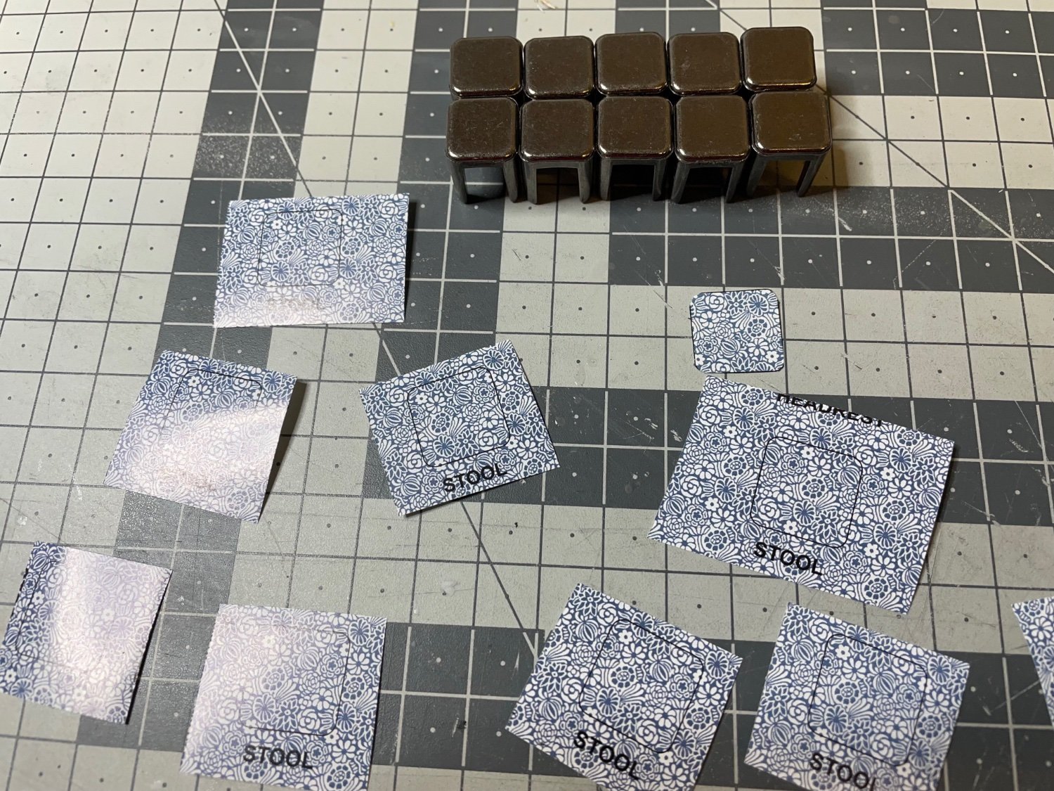
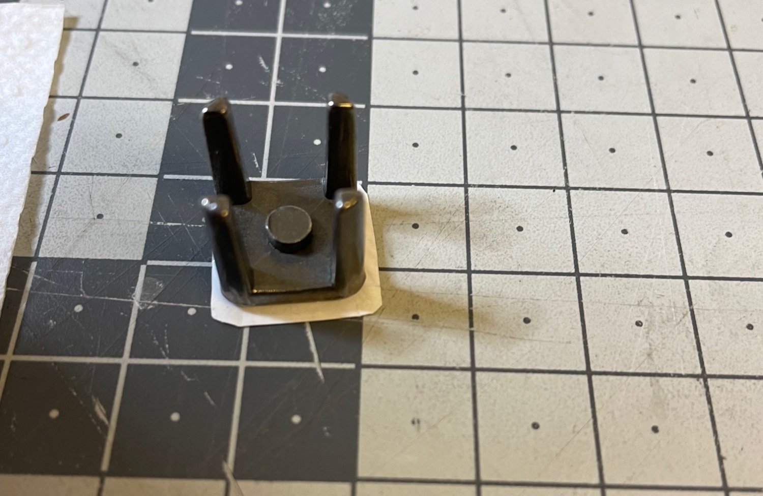
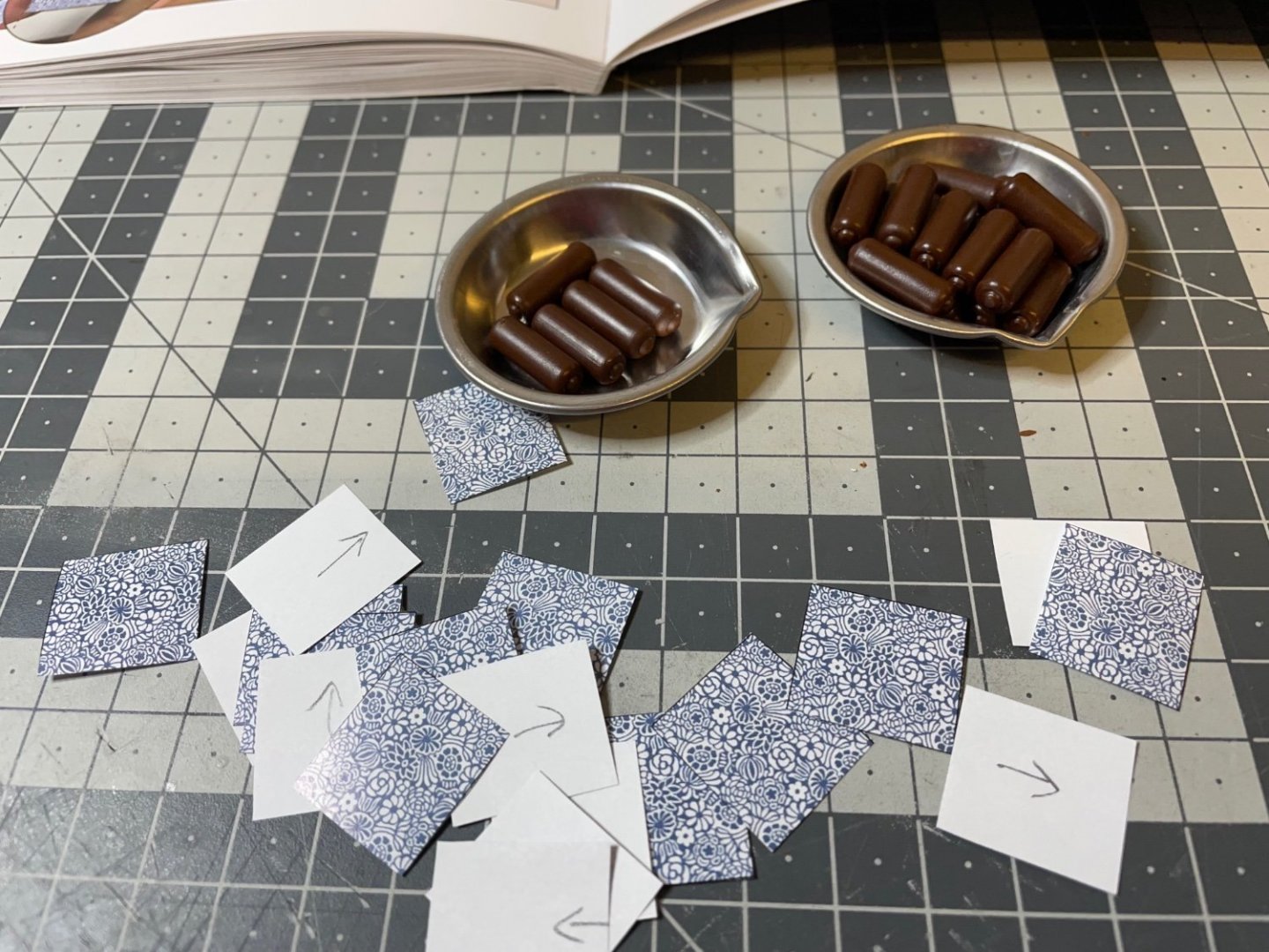
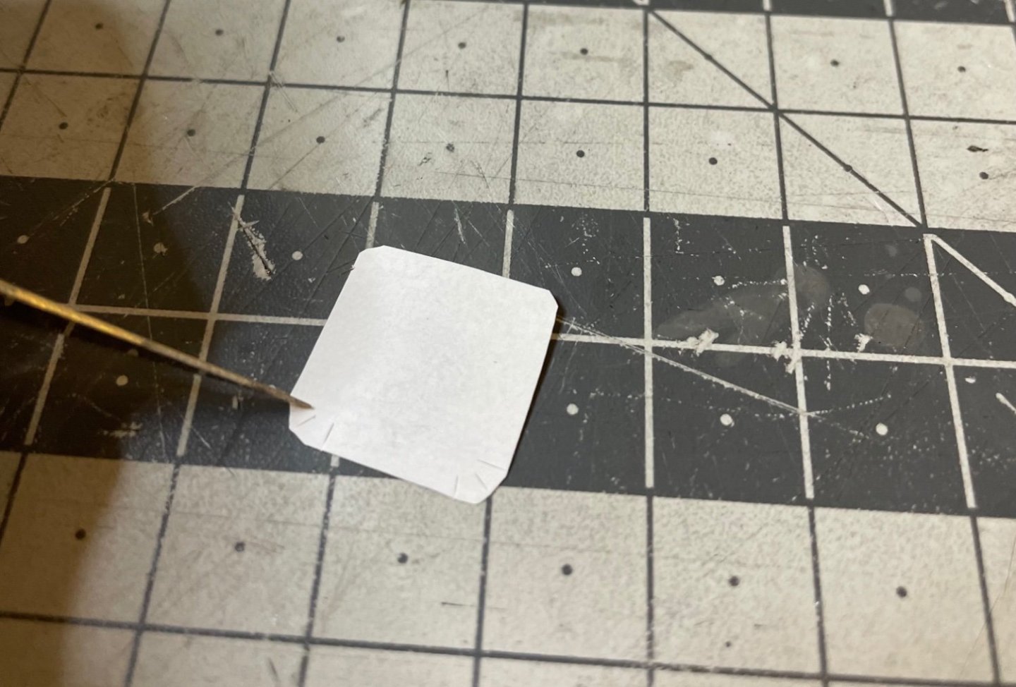
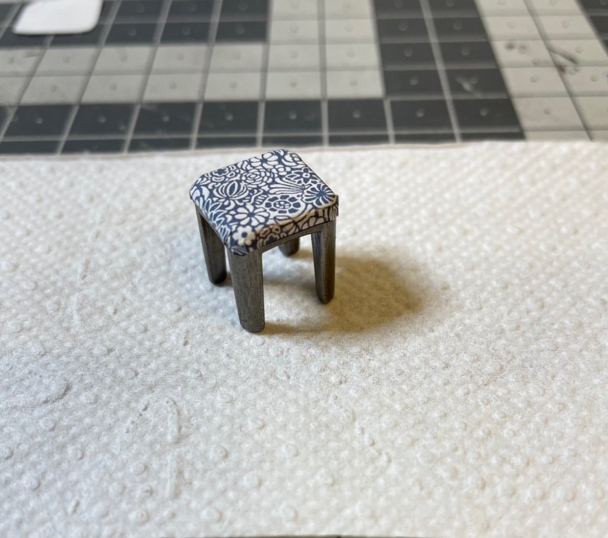
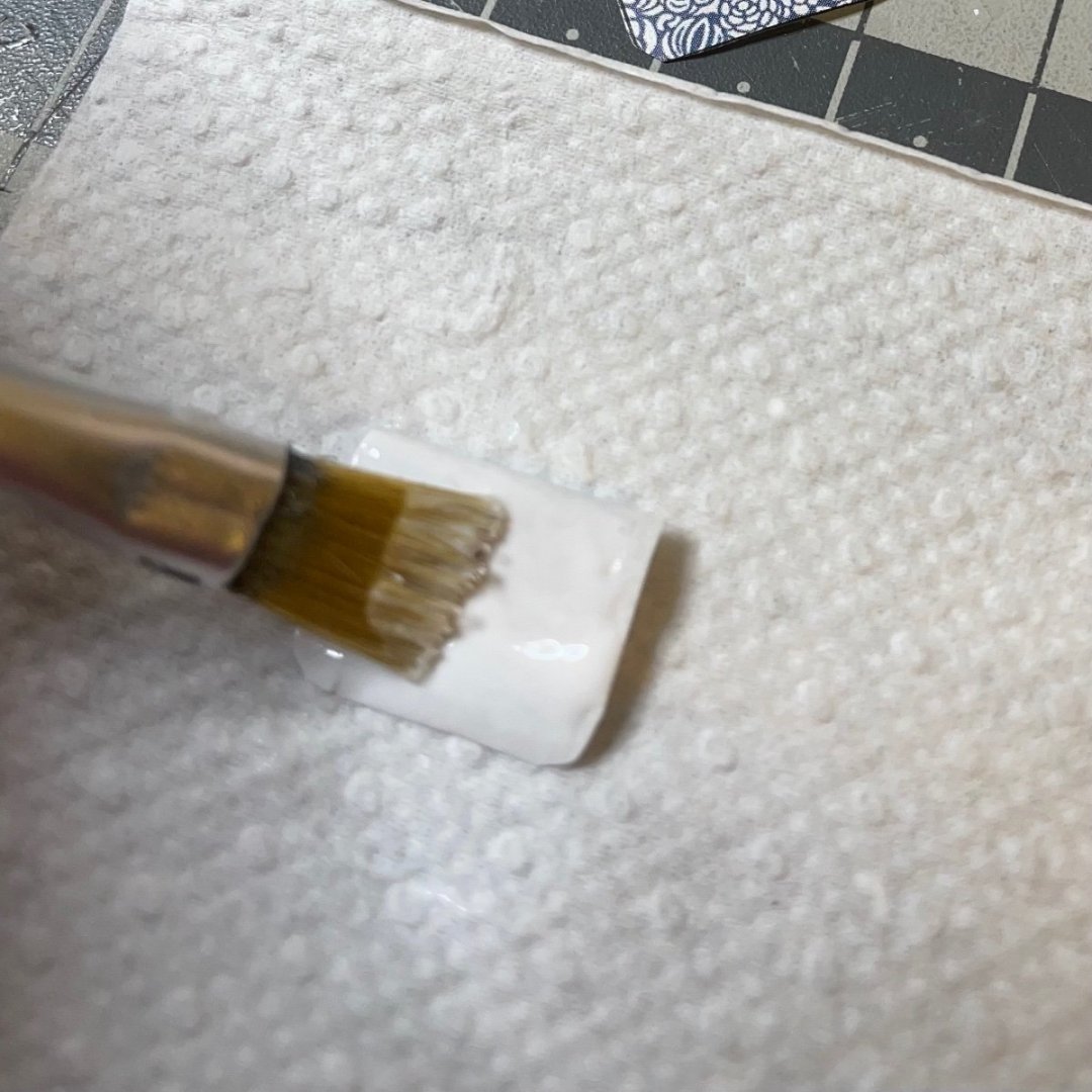
BUILD DAY 23 / 3 hrs / (TOTAL: 65 hrs) Today I had a lot of fun with papers building the compartment furnitures: Stools, divans, beds, armrests and backrests. Stools: One per compartment. They are made of metal, as opposed to plastic in the instruction manual. They look very nice and feel heavy in the hand. The instructions tell to paint them in black but I opted to leave them as they are, in order to expose the beautiful metal structure visible. Figure 224: 10 stools and their upholstery from paper. Figure 225: Small slices in the corners for folding over nicely. Figure 226: Brush an even layer of white stationary glue. Figure 227: Tip the stool over the center of the glued paper. Figure 228: Turn it over and fold the sides. There you go. Now repeat the steps for the remaining 9 stools


-
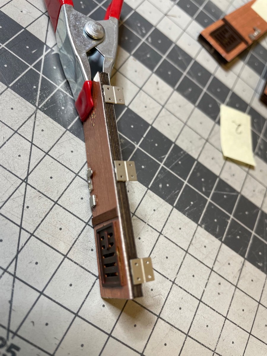
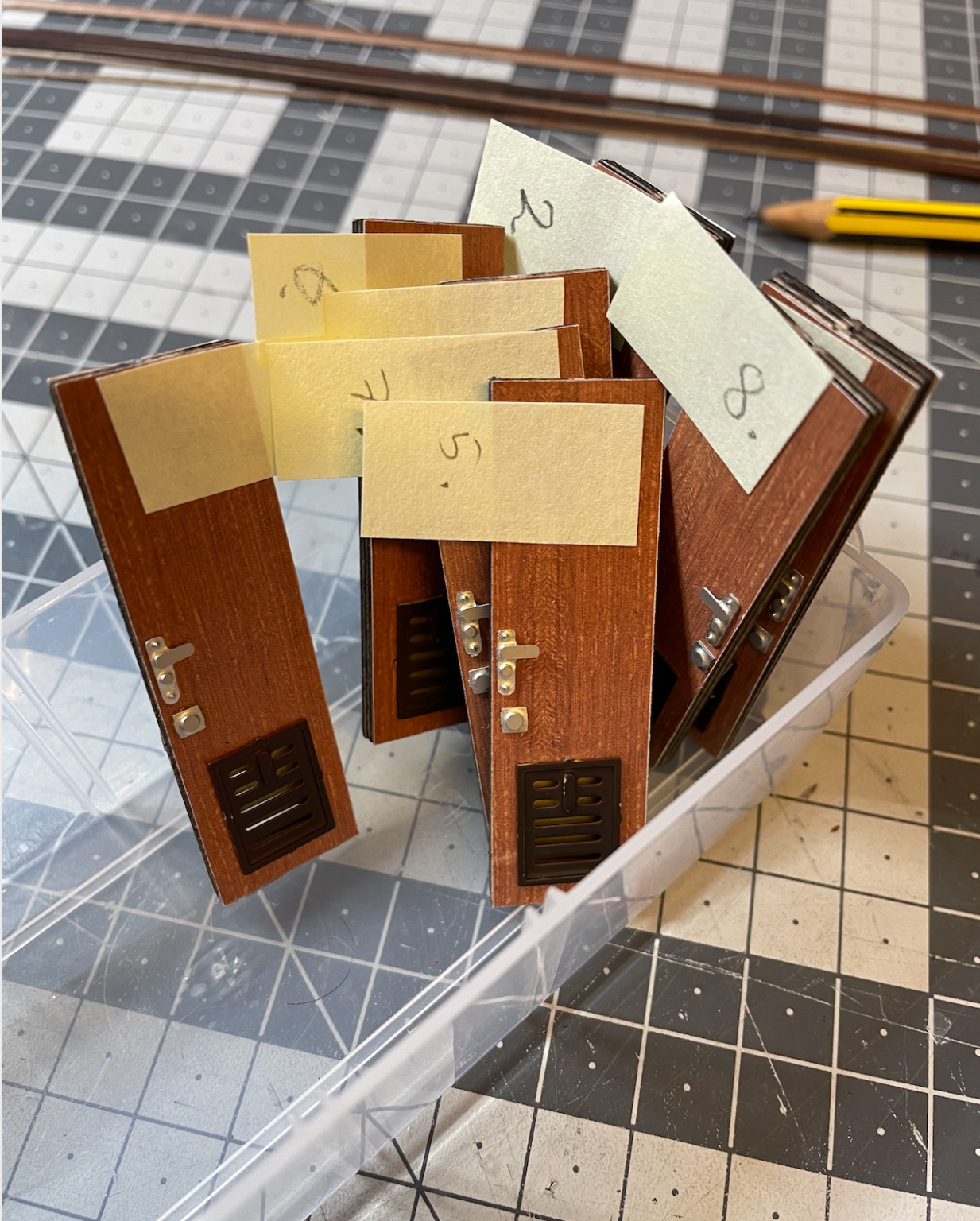
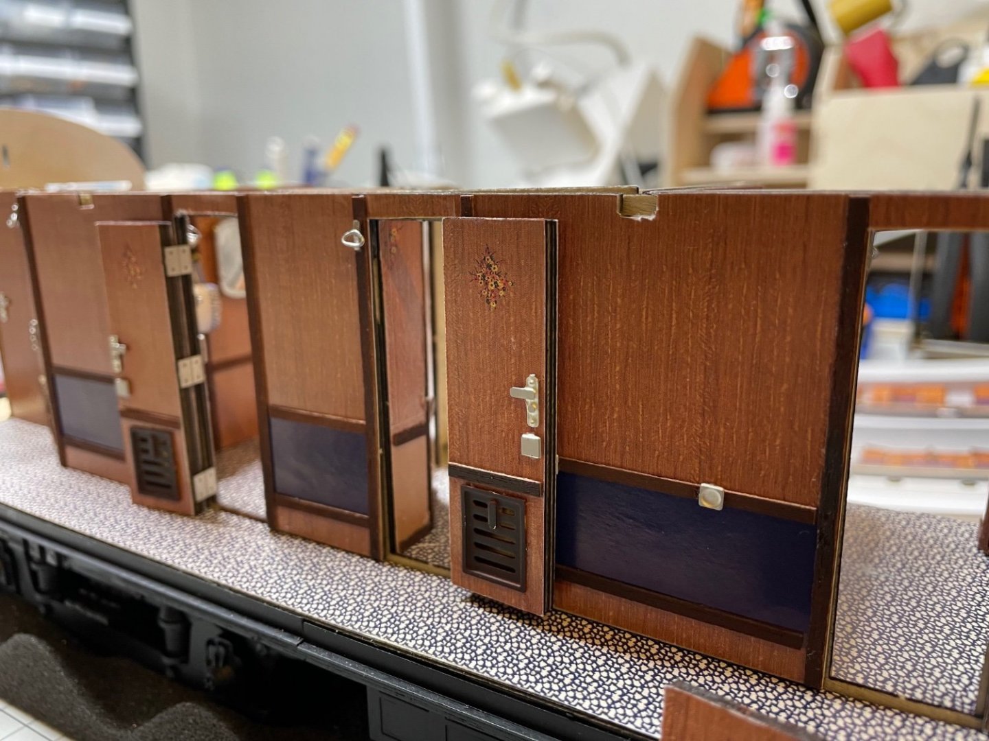
Figures 220-223: Compartment doors opening to the corridor. Also here I chose to leave some of them open, some of them closed. For the open ones I need to glue the hinges as they will be visible, in addition, I paint the door and frame edges to brown (same with the open inter-compartment doors in the post above). Since most of these doors open to a narrow corridor, they cannot be left "half" open otherwise they would block the passage. They need to rest to the wall properly. That's why they have door stoppers. The 1st, 10th and W-C doors don't have door stoppers since there is more space in front of them. A nice detail. That's all for today. Thanks for watching!


- 293 replies
-
- 16
-
-
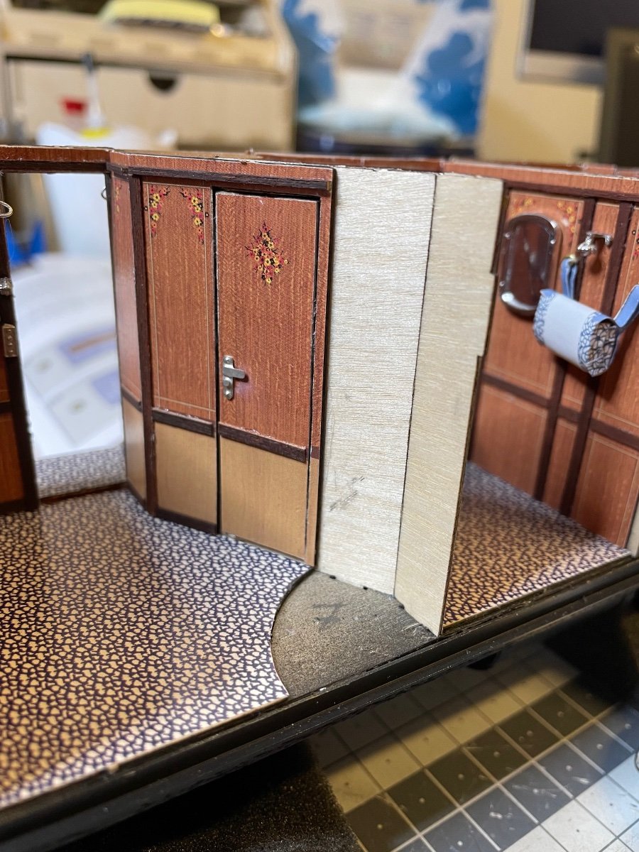
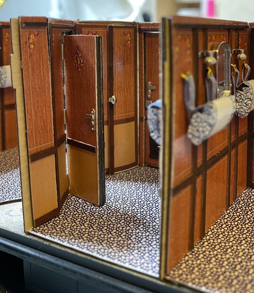
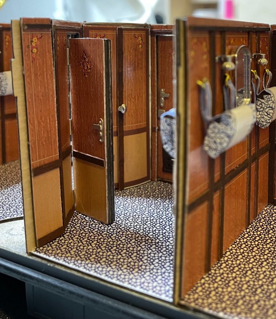
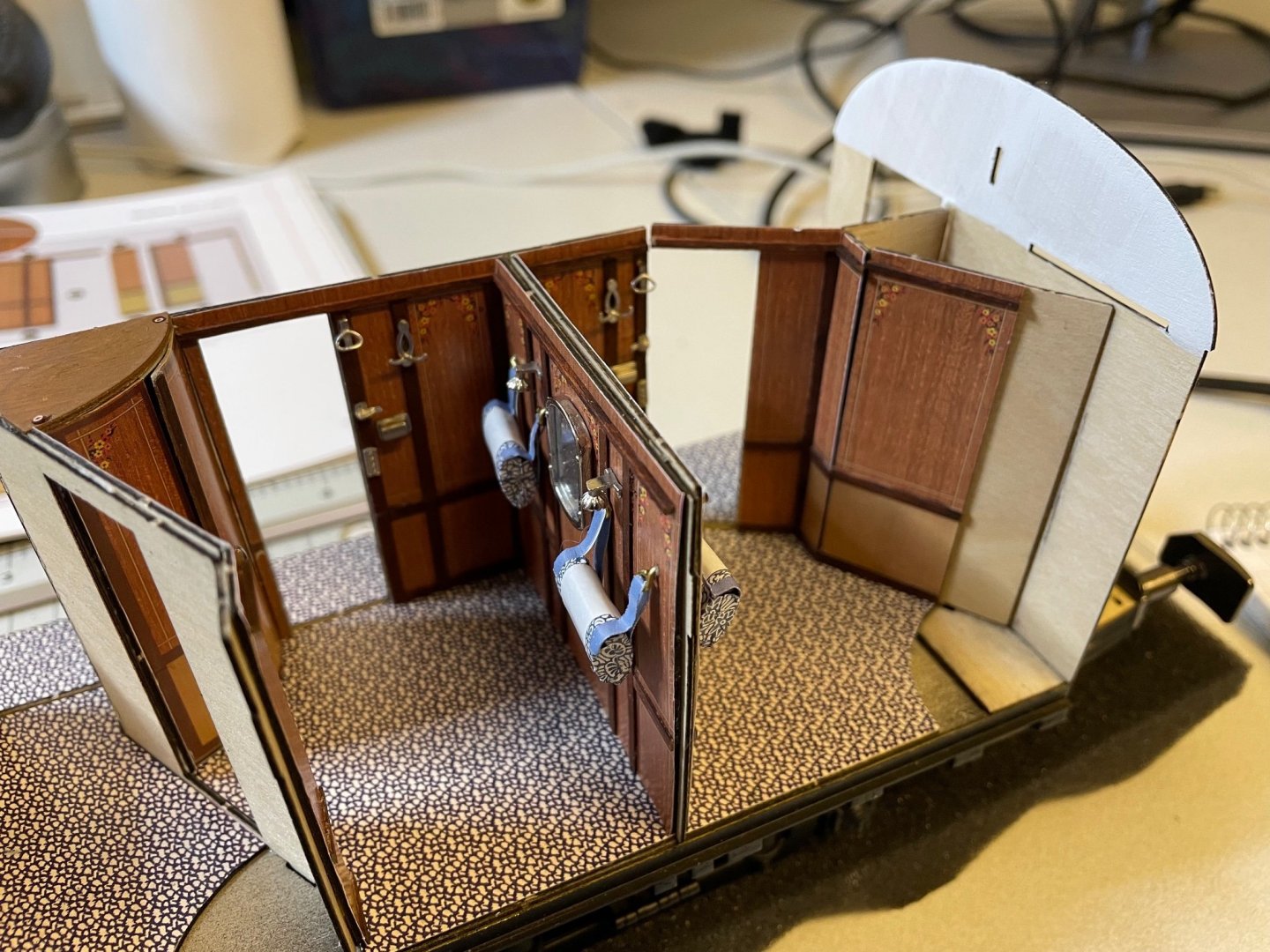
Figures 216-219: Intra-compartment doors. There are four of them between 2nd-3rd, 4th-5th, 6th-7th and 8th-9th compartments. 1st and 10th compartments are without any inner connection to another compartment. I decided to install two of them closed and two of them open. I keep the open ones just partially open instead of leaning fully back on the wall. To do this I bend the hinges to a little angle (see last two photos below).


- 293 replies
-
- 14
-
-
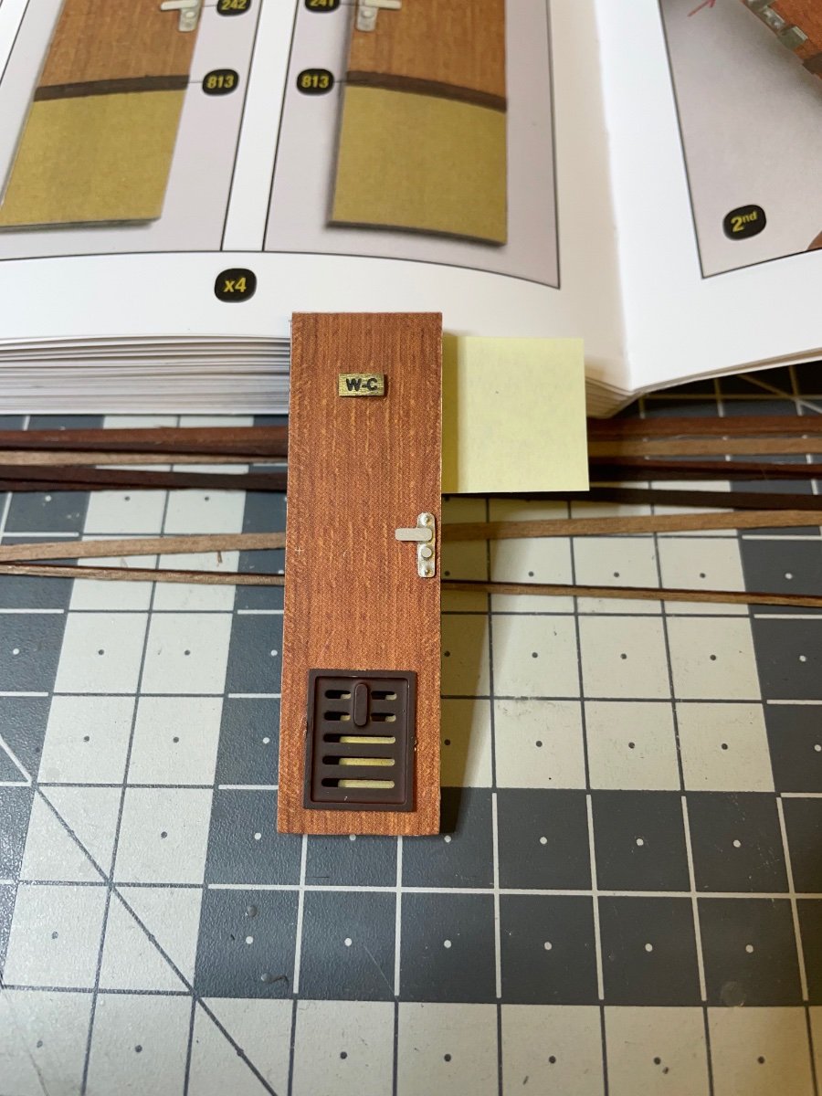
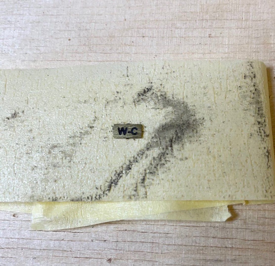
BUILD DAY 22 / 1,5 hrs / (TOTAL: 62 hrs) Figure 214: WC nameplate, apparently written "W-C" back in the days . I painted the whole brass piece in black and then sanded off the surface to leave only the engraved letters colored. Figure 215: Nameplate in place.

- 293 replies
-
- 11
-
-
Even though I was sceptical, too, about paper decorations at first, I have to say that the print quality of the paper decorations is extremely good and realistic, plus, the real mahogany wooden strips add to the realistic feel. My photos are very close shots, maybe you can get the paper feeling when you look at the big sized photos, but looking at the model with bare eyes from a reasonable distance it is really hard to tell that they are papers. Besides, maybe in the original train the walls were covered with actual wall papers, who knows? Having said that, I would prefer the carpet to be made of fabric instead of paper. I believe it is possible to print them on a fabric.
-
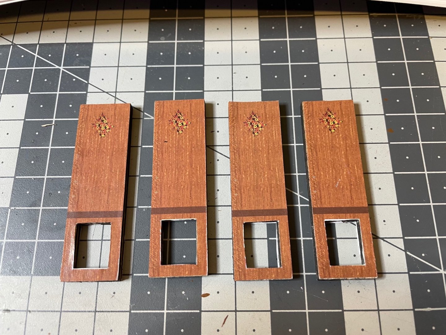
Figure 213: Doors getting ready one by one. That's all for today. Thanks for watching!

- 293 replies
-
- 12
-
-
Figure 212: Ventilation grids painted in brown using airbrush, leaving a nice pattern on the nylon cover

- 293 replies
-
- 10
-
-
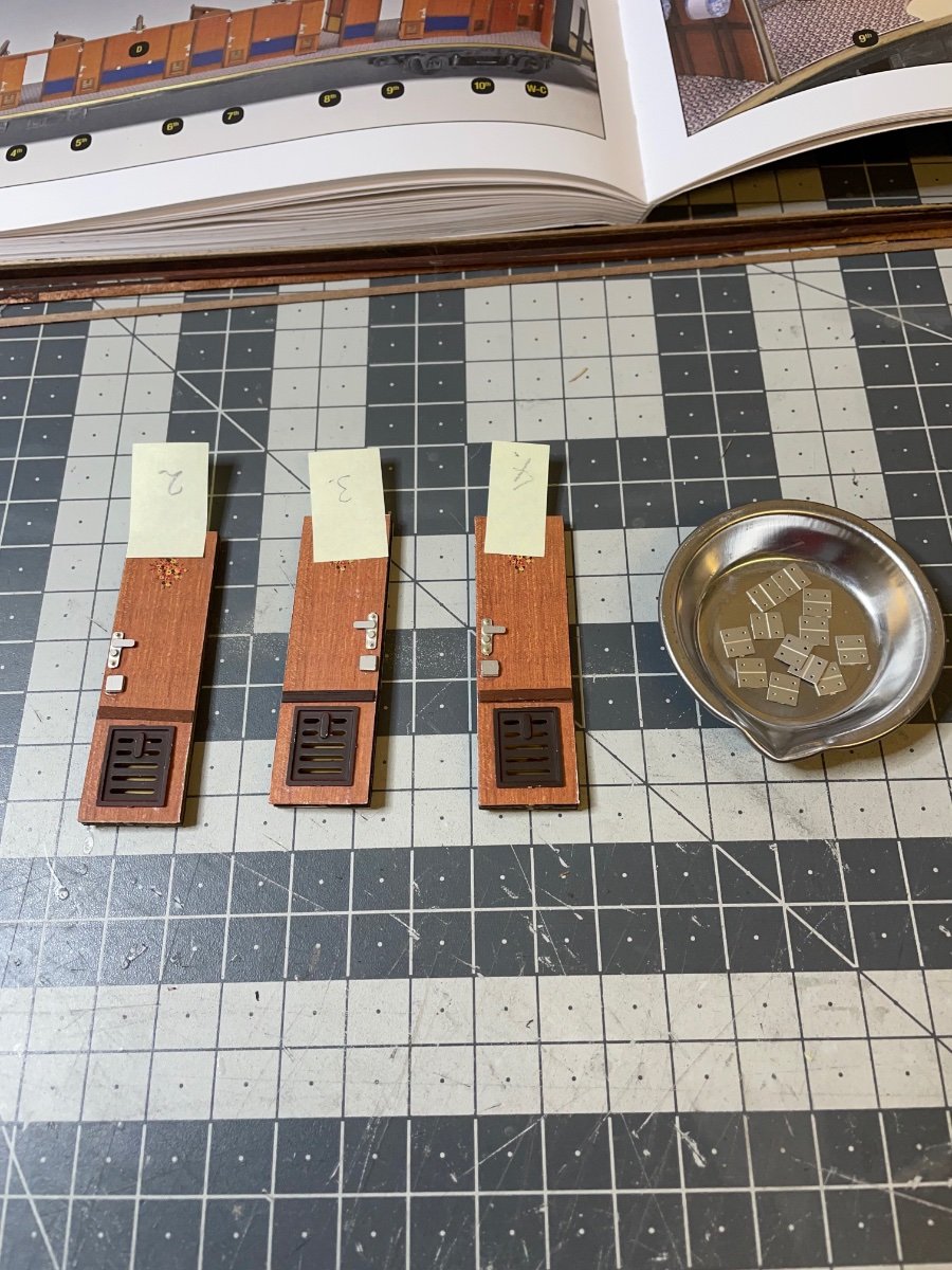
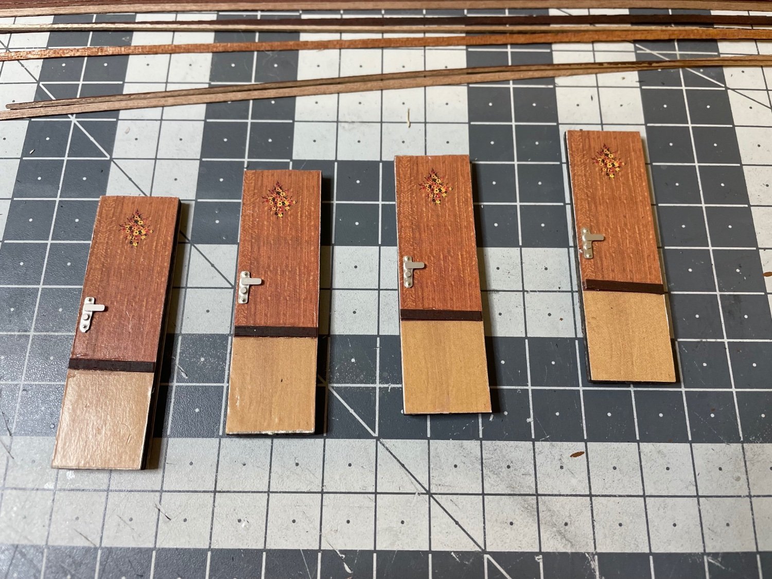
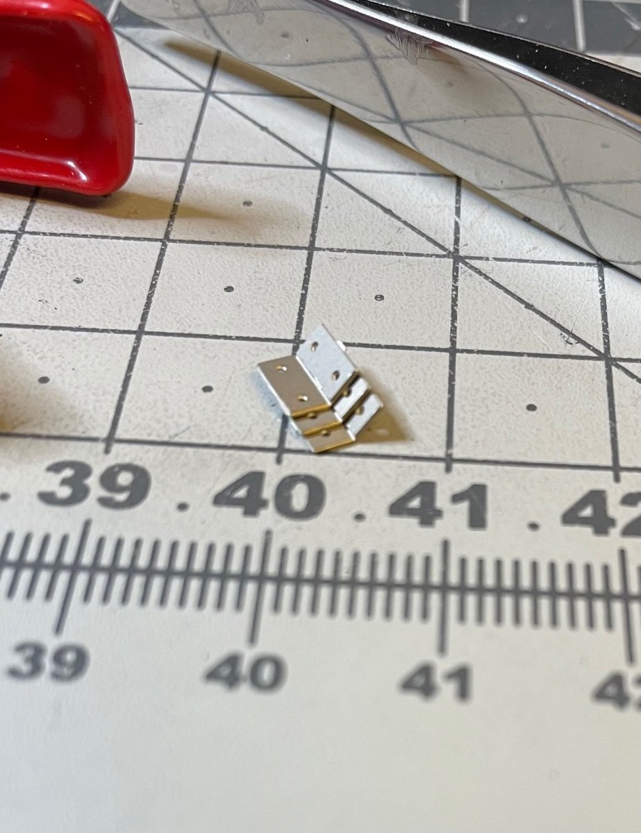
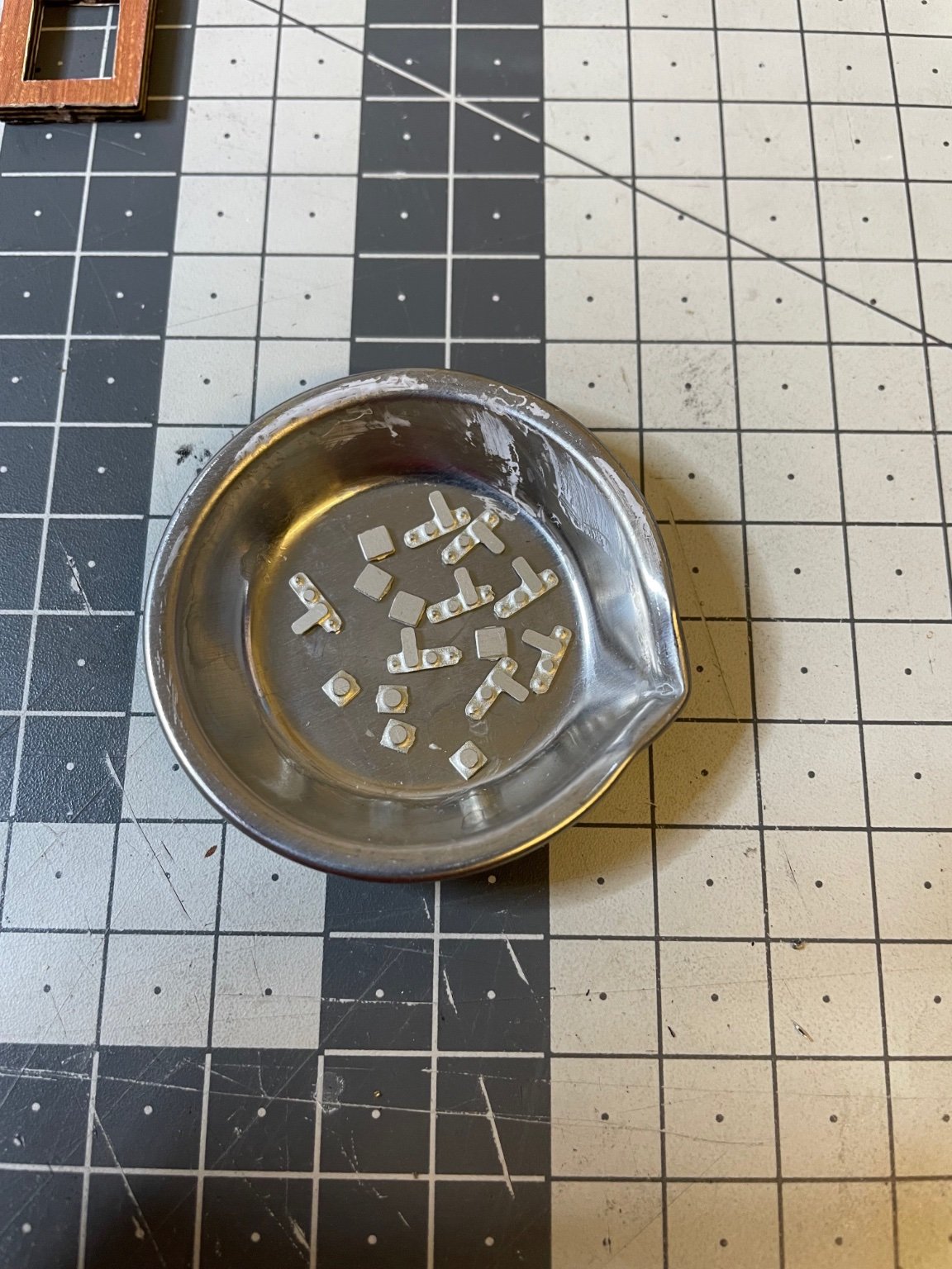
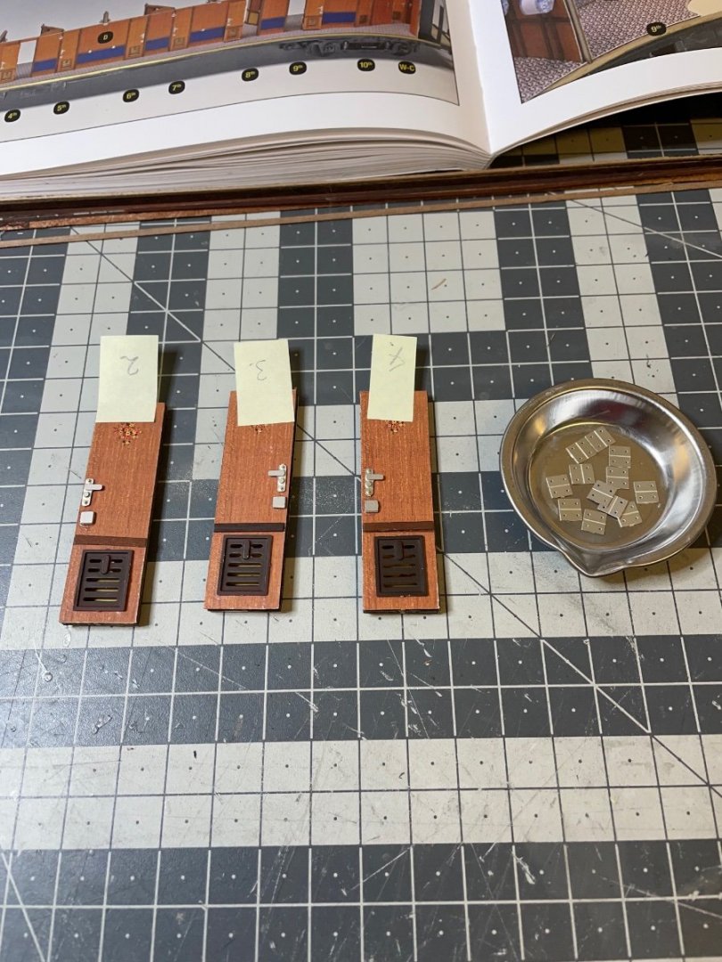
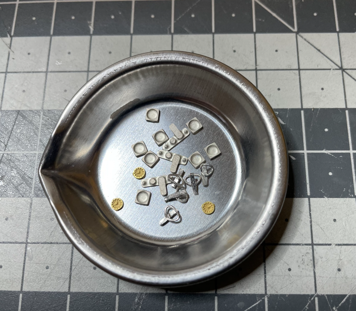
Figure 211: Door handles and stoppers to be glued on the doors.

-
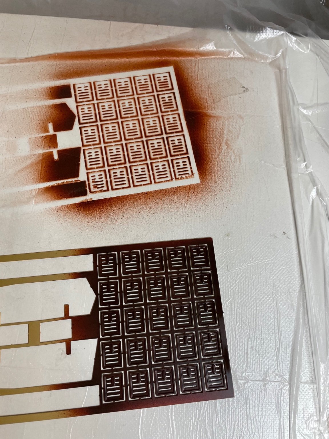
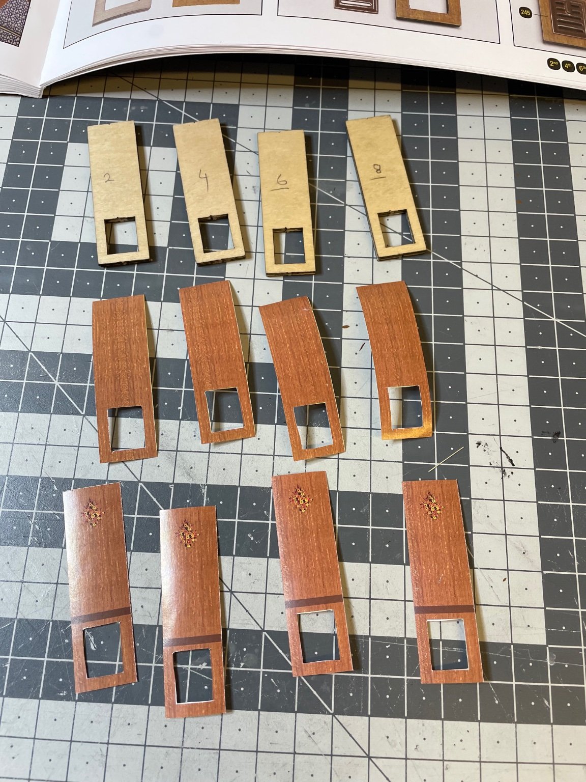
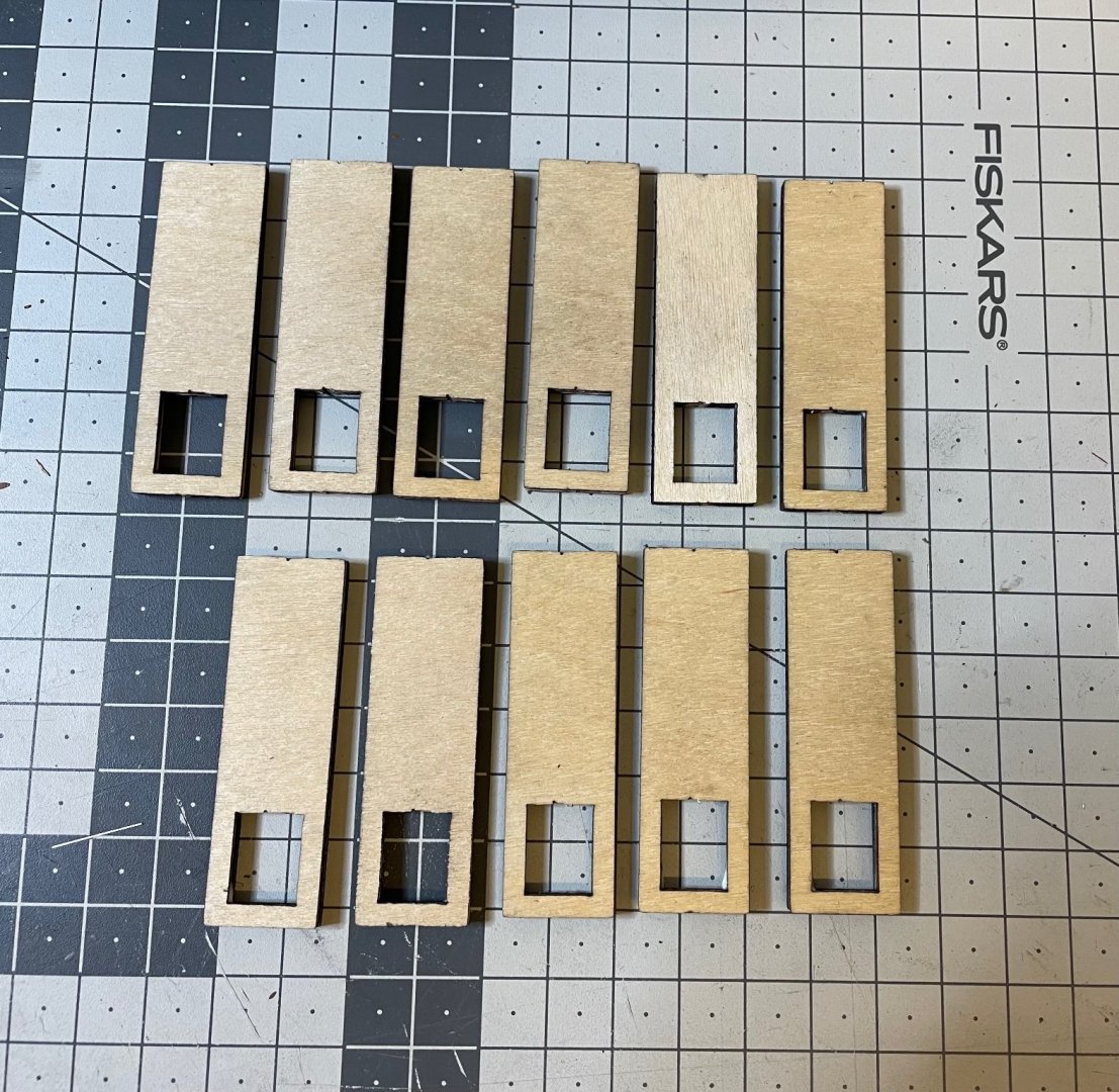
Figure 207: Door parts. Each 3 piece is glued together to form one thick door. So there will be 11 of them, 10 for the compartments and 1 for the WC. These are the ones opening to the corridor. They are distinguishable from the ventilation grills at the bottom. Figure 208: Parts glued together to form 11 doors. Figure 209, 210: Paper decorations cut off and glued on both sides.


-
BUILD DAY 21 / 2,5 hrs / (TOTAL: 60,5 hrs) Next in the line is construction of the doors. Some of them are false doors (e.g. those of the boiler room, dress cabinet etc) as you may see in Figure 206, but most of them will be actual doors as below: - Compartment doors opening to the corridors, - WC door, - Doors dividing the compartments. Some of these doors will be installed open, some closed. I don't know yet if it is up to the builder to decide, so far I guess I will just follow the plans.
-
Figure 205: Gauges painted and glued on their place. Figure 206: Corridor wall installed. That's all for today! Thanks for watching!

- 293 replies
-
- 16
-
-

-
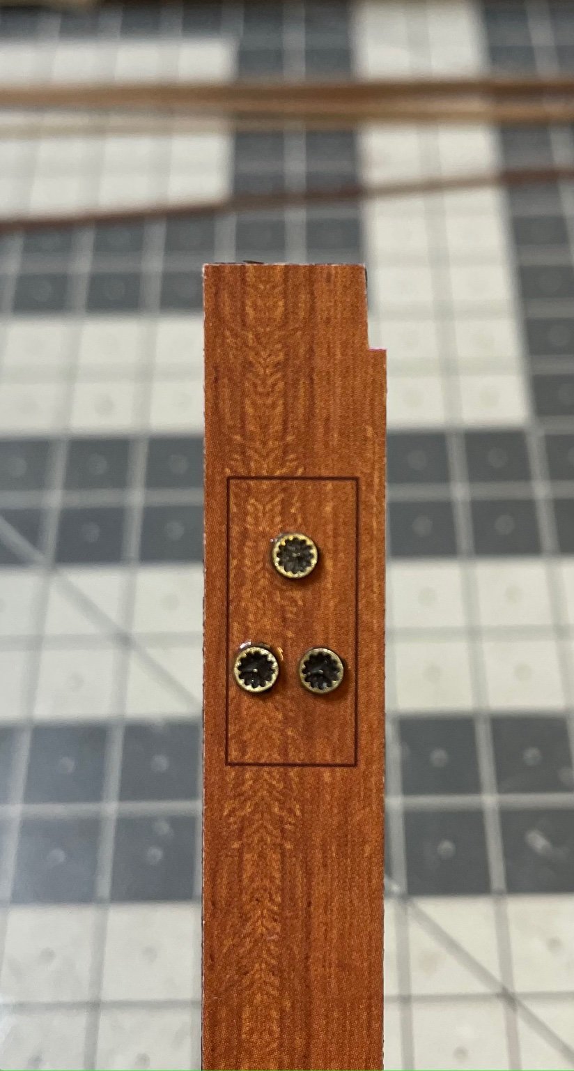
Figure 204: Accessories on the corridor walls. The square pieces with the concave circular center are door stoppers. They will have matching ones on the doors with a convex circular center. Nice detail.
-
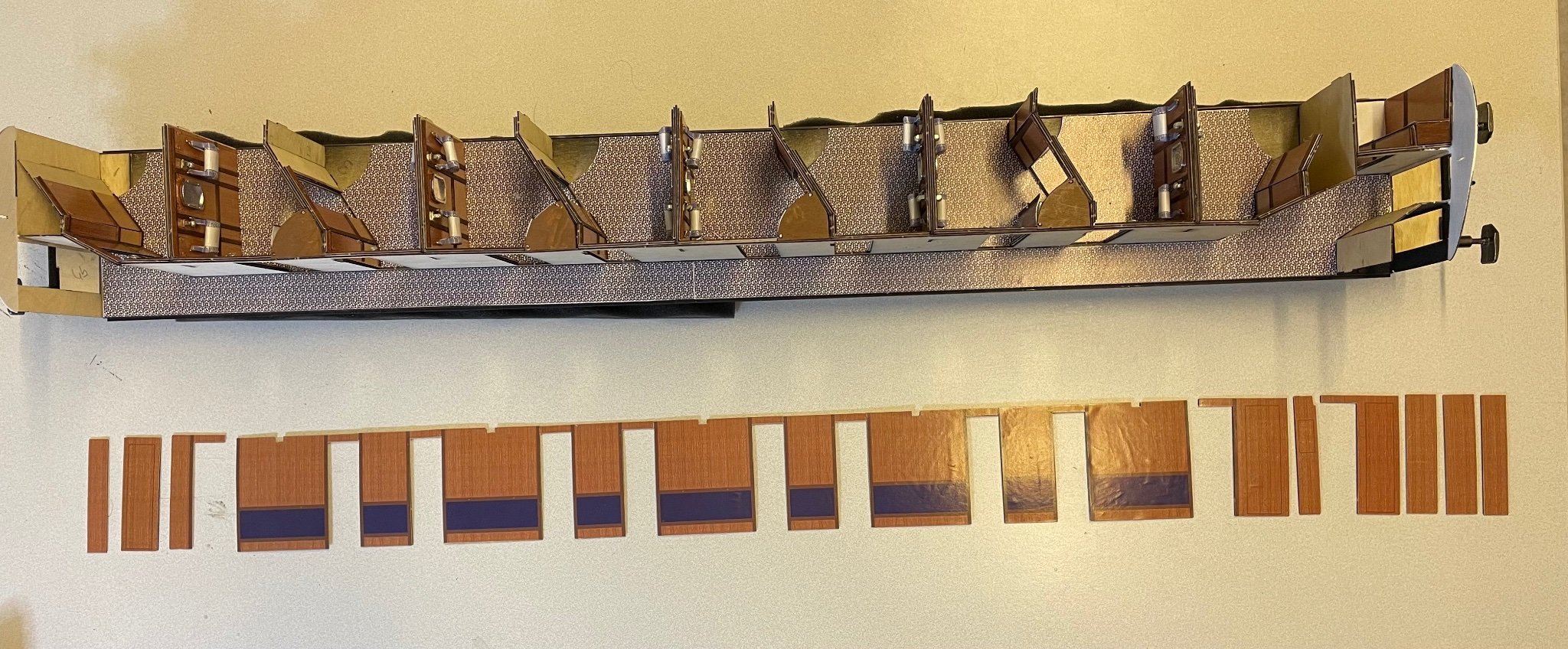
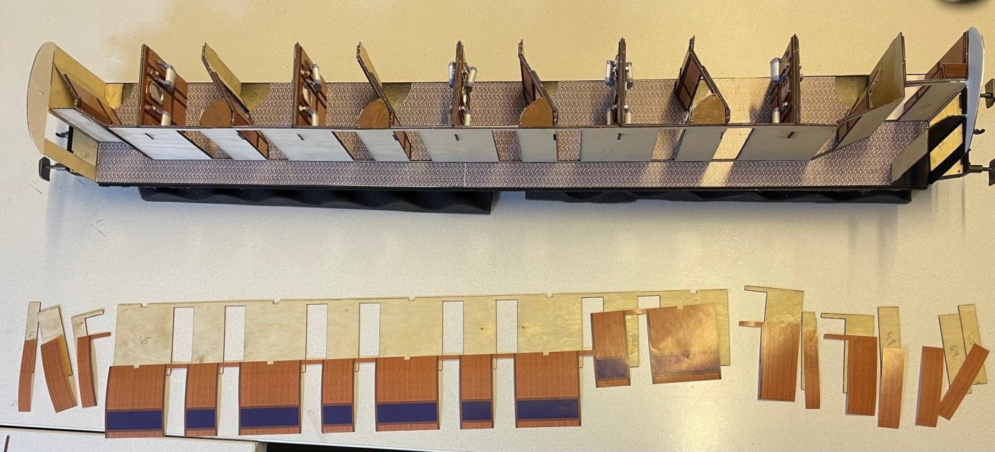
Figures 202, 203: Corridor inner wall structure and matching paper sheets, then glued. Again I used X-acto knife and a steel ruler for cutting the paper.

-
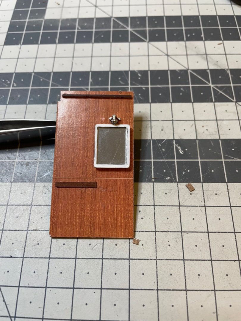
BUILD DAY 20 / 4hrs / (TOTAL: 58 hrs) I have spent 4 hours for the inner corridor wall and a few details like the WC wall. Figure 201: Lovely WC wall . The sink will be installed later.
-
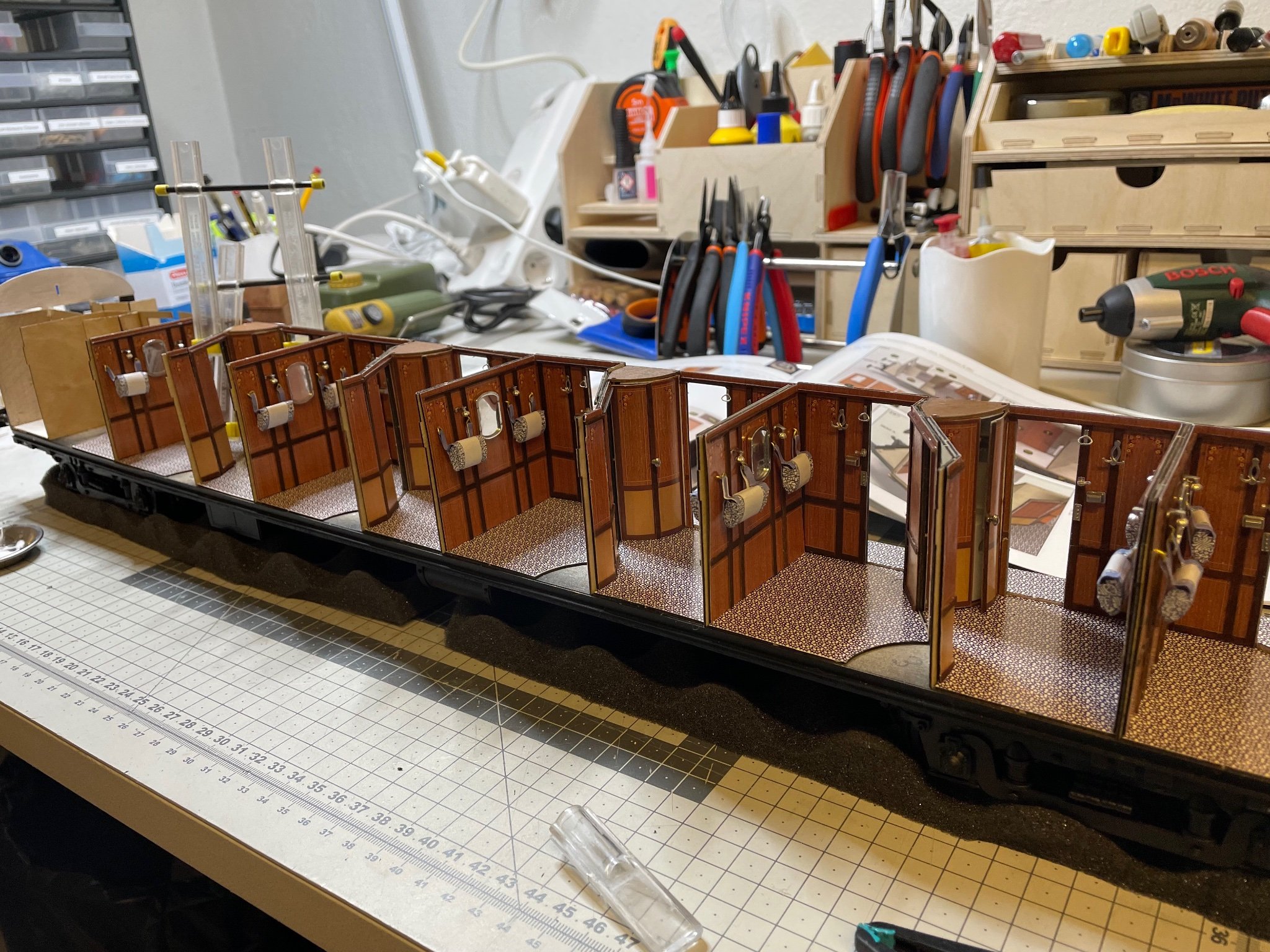
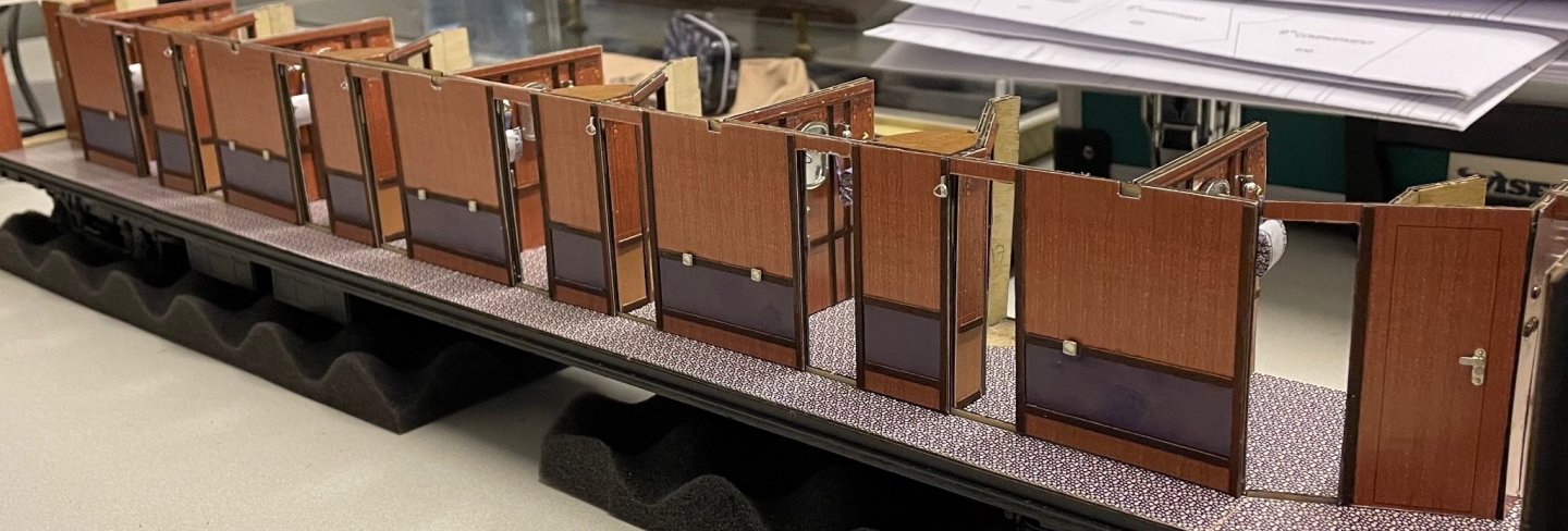
BUILD DAY 19 / 6hrs / (TOTAL: 54 hrs) Back in business after a few weeks of planned absence Today I finished installing the walls of compartments 3, 5, 7 and 9, which are identical to each other. This means compartment #10 and the WC are remaining next. You see at the far end of the first picture below. Figures 199, 200:


- 293 replies
-
- 12
-
-
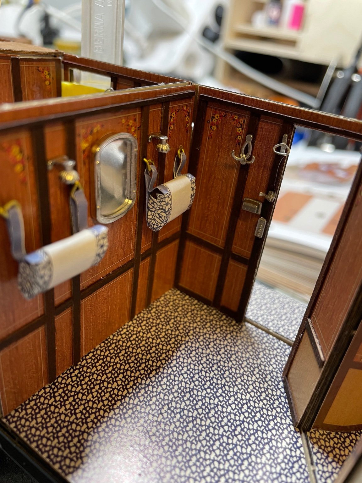
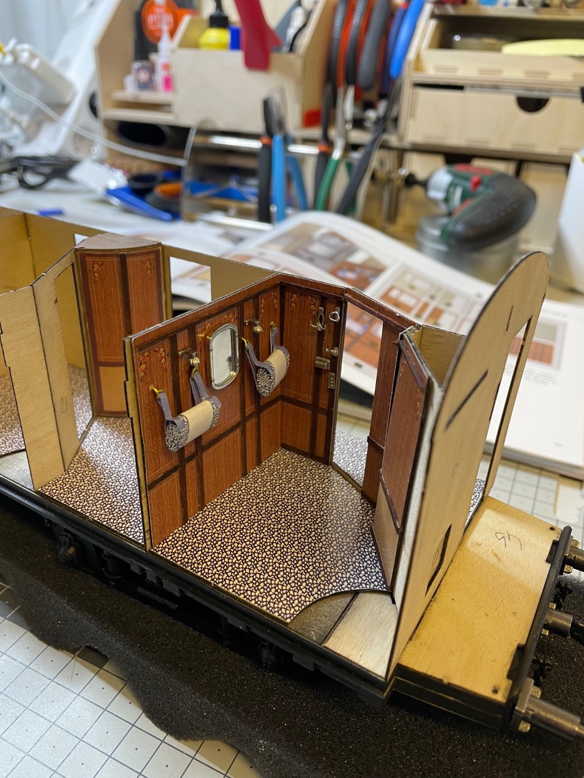
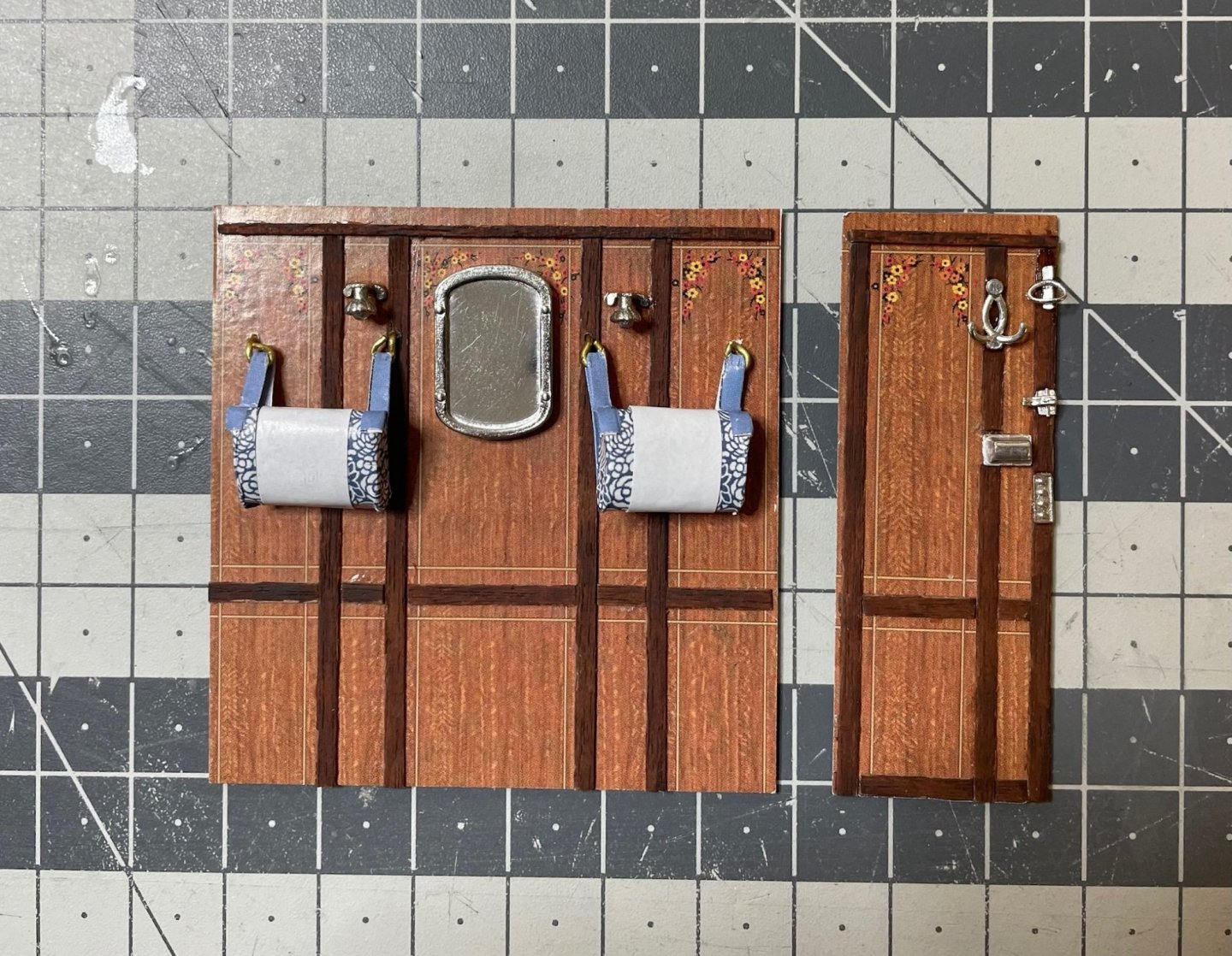
Figure 197, 198: Walls with ornaments and headrests in place for compartments #1 and #2. The walls on the window side will be installed later. Same goes for compartment #1's bathroom. The work will then continue for compartments #4, #6, #8 and #10, which are identical to #2. (post edit: #10 is different) Given the headrests have been prepared earlier, overall it takes roughly 1,5 hours per compartment to install these walls to the wagon. This 1,5 hour includes preparing the plywood parts and paper sheets, gluing them, cutting and gluing the wooden strips, gluing the accessories and the headrests in place and finally gluing the walls in their place. That's all for today and thanks for watching! Aydin

- 293 replies
-
- 15
-
-
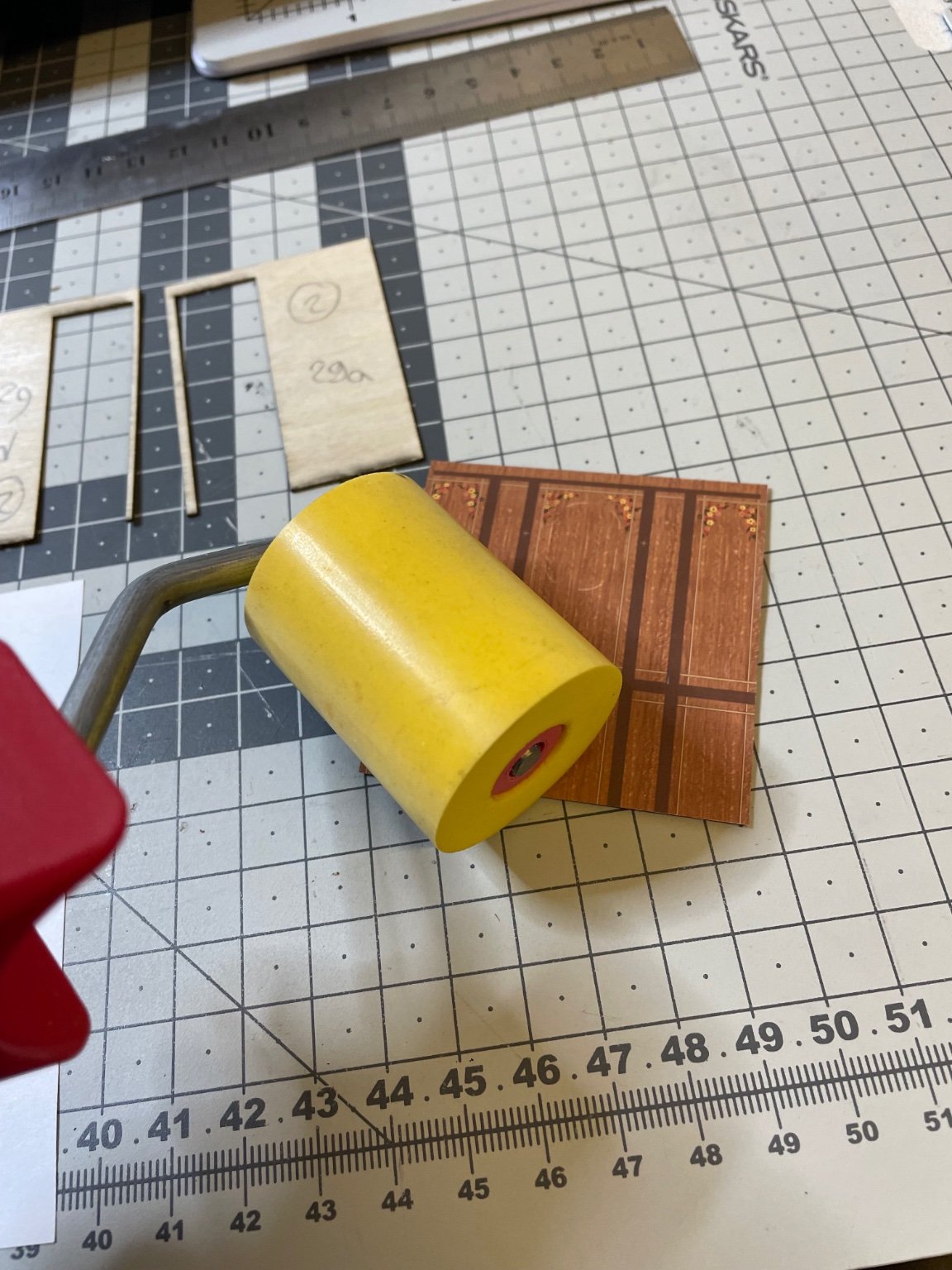
BUILD DAY 18 / 3hrs / (TOTAL: 48 hrs) Figure 196: I use this soft roller for ensuring the paper is pressed properly on the surface. I had bought this thing earlier for another project, covering a speaker cabinet with veneer.

-
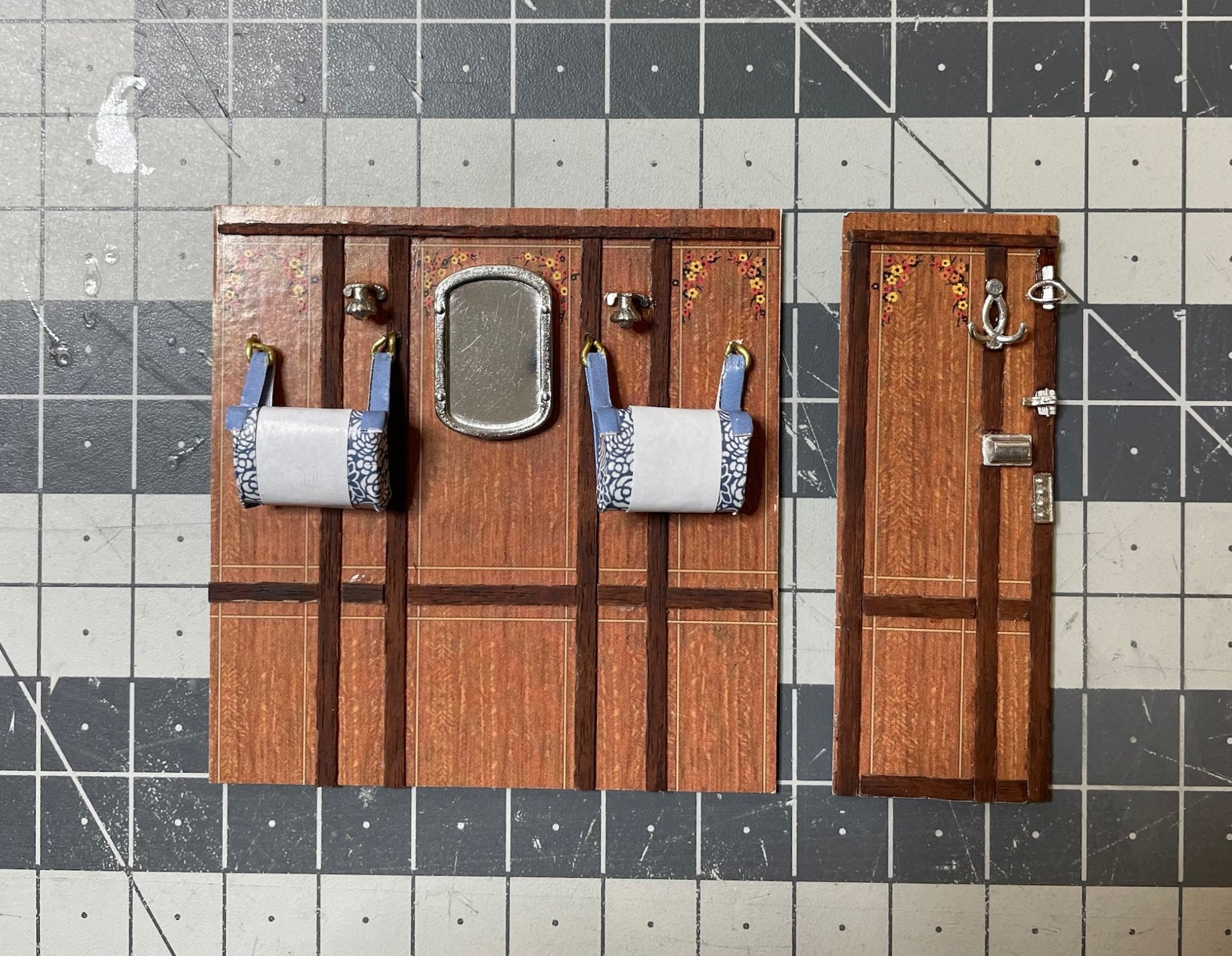
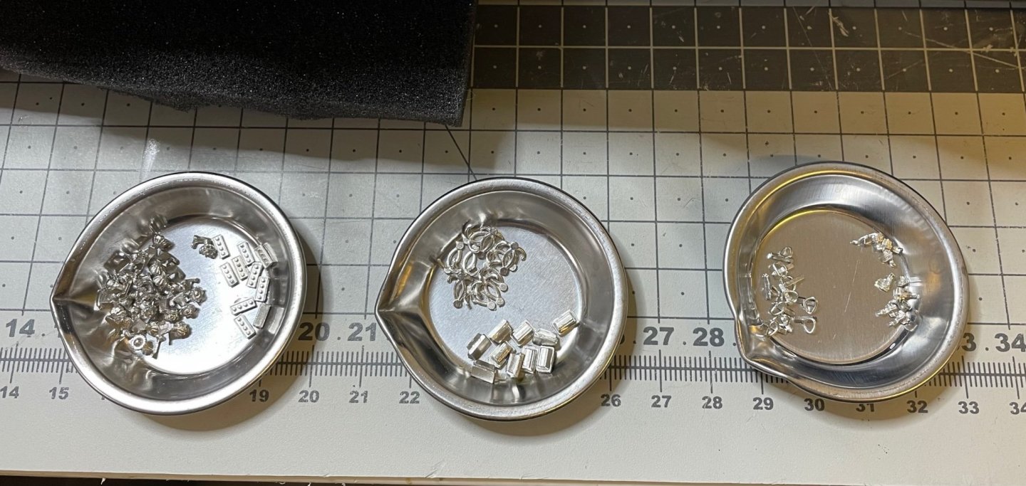
A short update on my progress. Figure 194: The wall accessories sorted in cups. Figure 195: Headrests and the wall ornaments installed for compartment #1. Note I also painted the walnut strips in mahogany color, as in instructions. This color surely fits better than walnut here. I had mentioned above that I also bought mahogany strips to use here, however I think the mahogany paint over walnut looks better. So, I am not thinking of using mahogany at the moment.
- 293 replies
-
- 11
-