HOLIDAY DONATION DRIVE - SUPPORT MSW - DO YOUR PART TO KEEP THIS GREAT FORUM GOING! (Only 20 donations so far - C'mon guys!)
×


aydingocer
-
Posts
916 -
Joined
-
Last visited
Content Type
Profiles
Forums
Gallery
Events
Everything posted by aydingocer
-
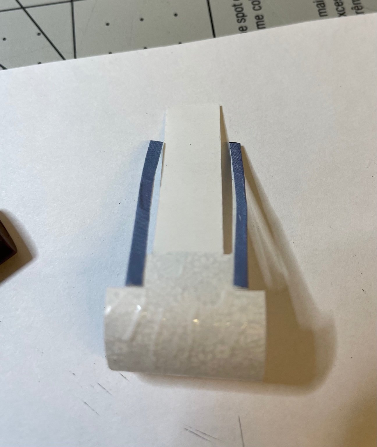
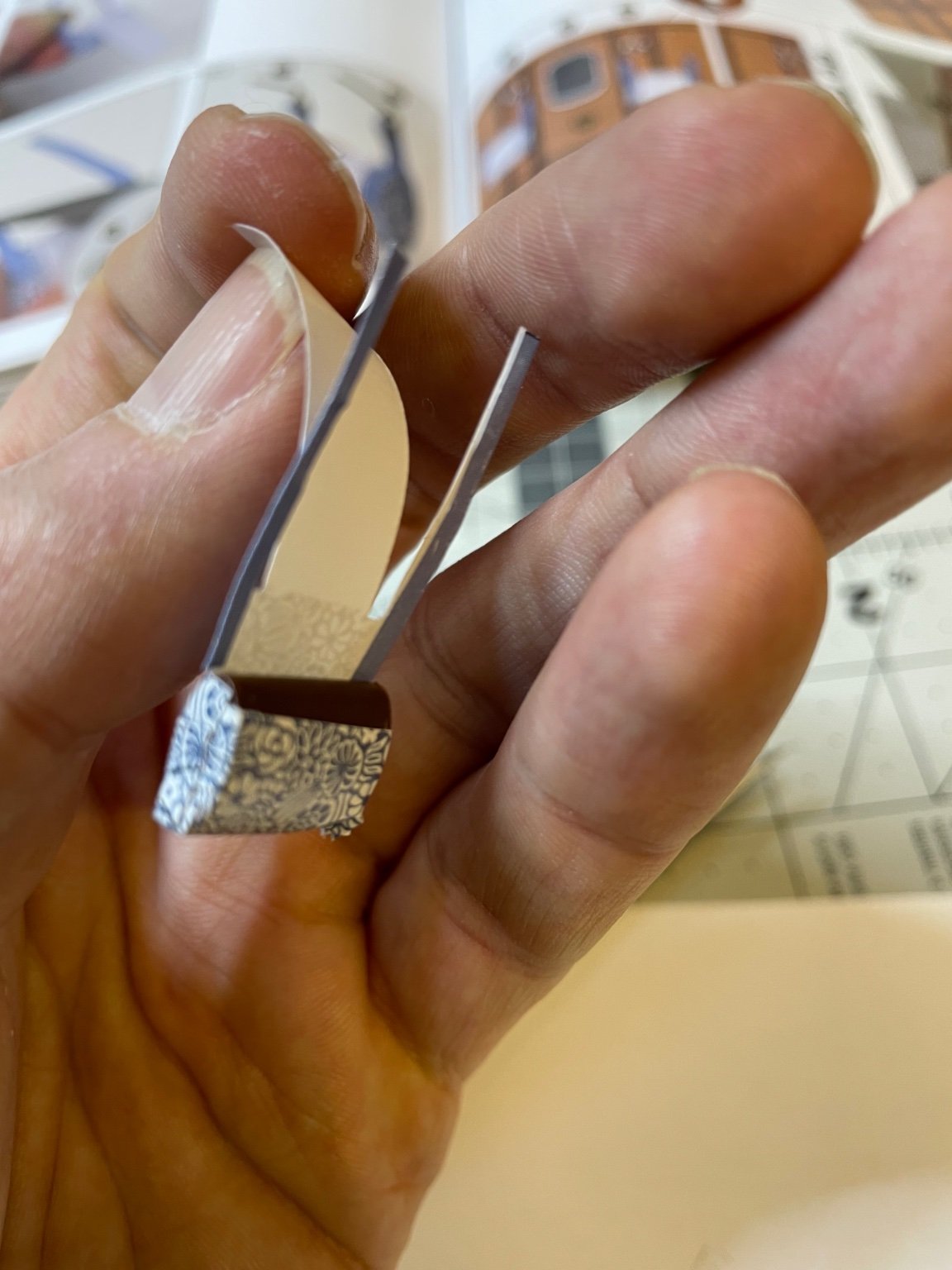
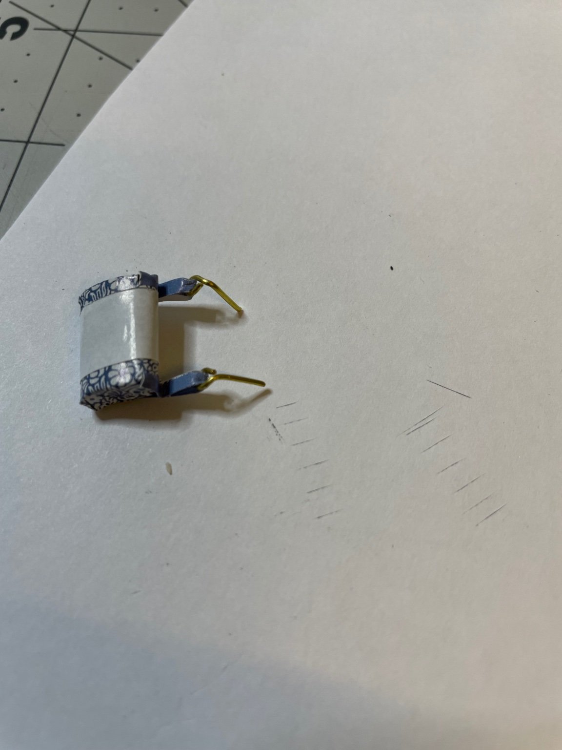
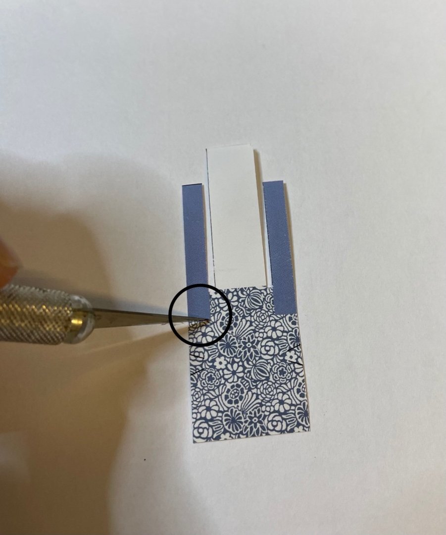
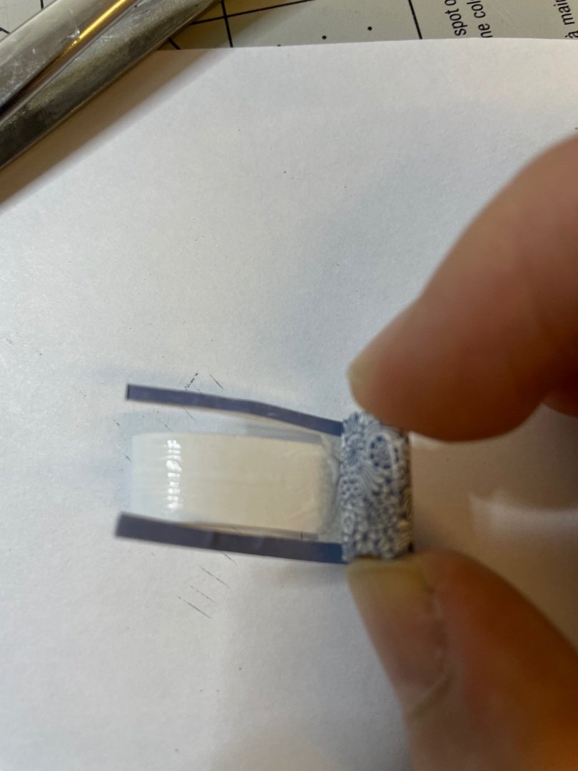
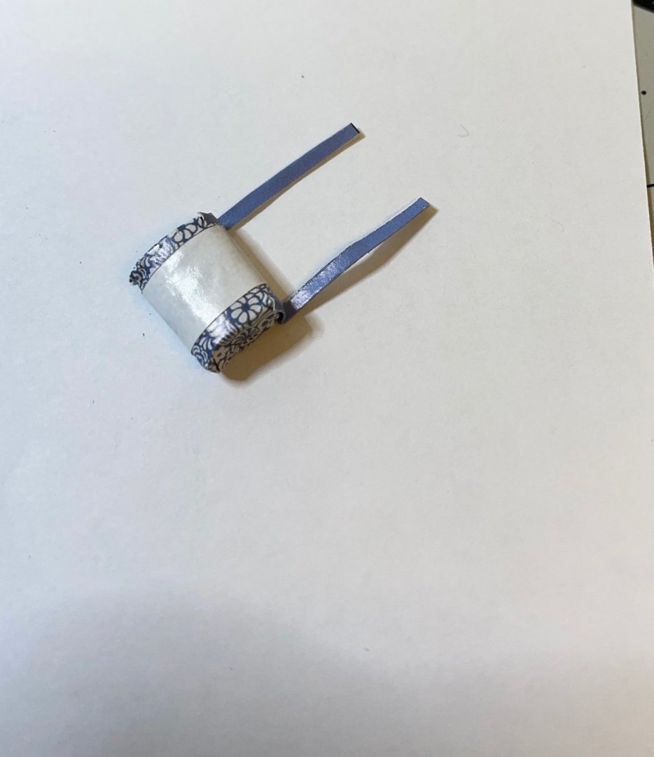
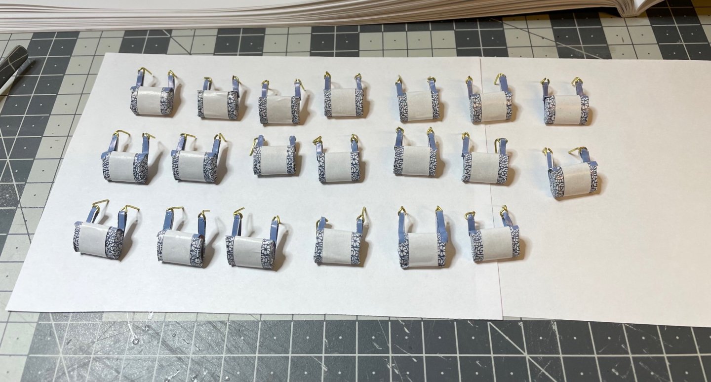
 BUILD DAY 17 / 3hrs / (TOTAL: 45 hrs) Headrests. There are altogether 10 pairs of them, one pair for each compartment. I applied white glue using brush until the last step, where I used superglue to fix the loops to the back. Figures 183-193: Below I am adding several photos showing the process. That's all for now! Thanks for watching!
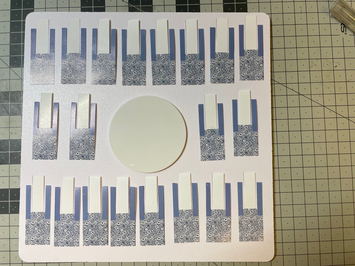


- 293 replies
-
- 15
-

-
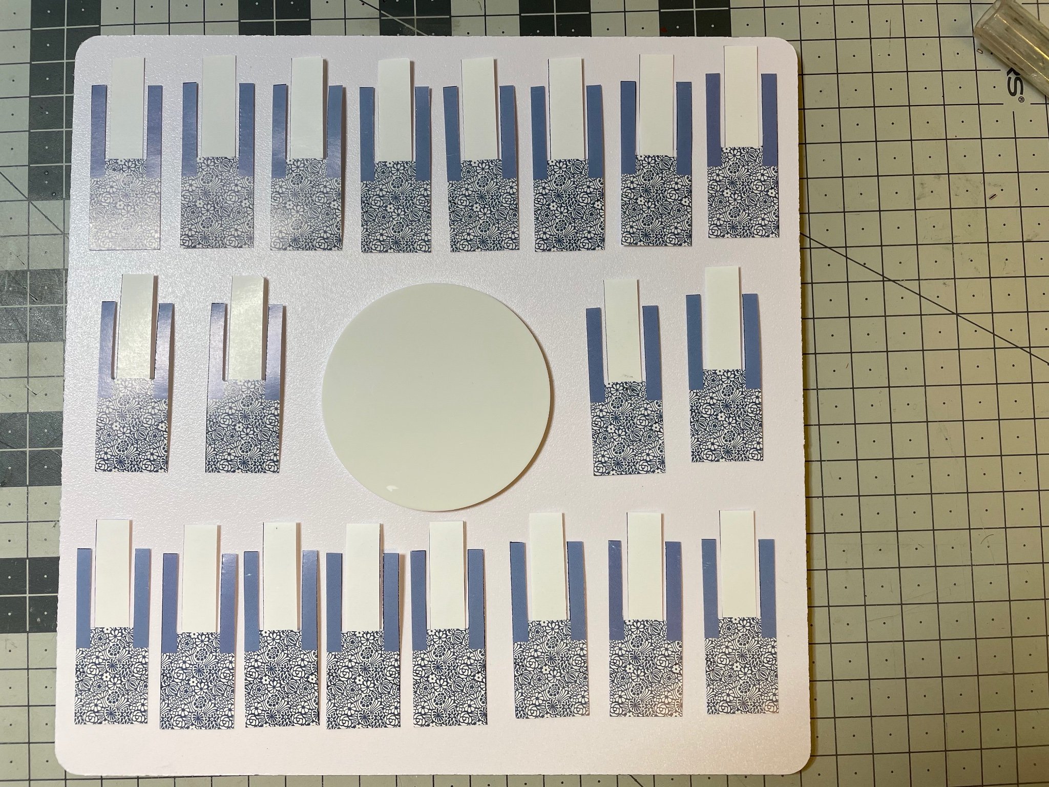
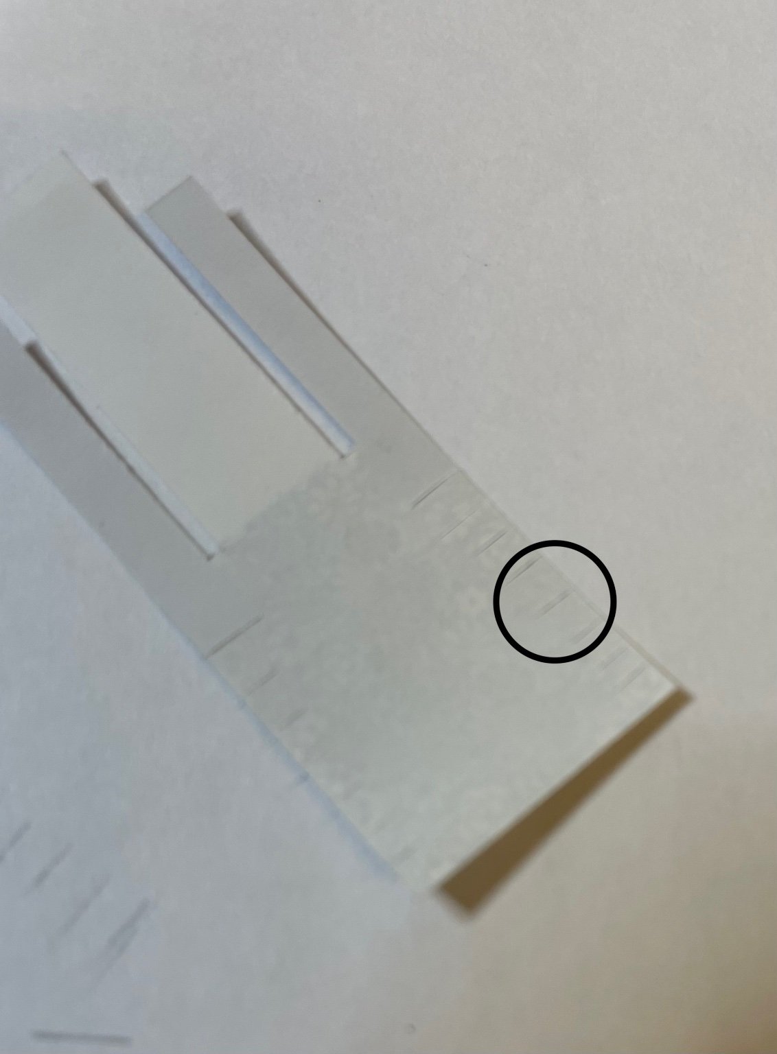
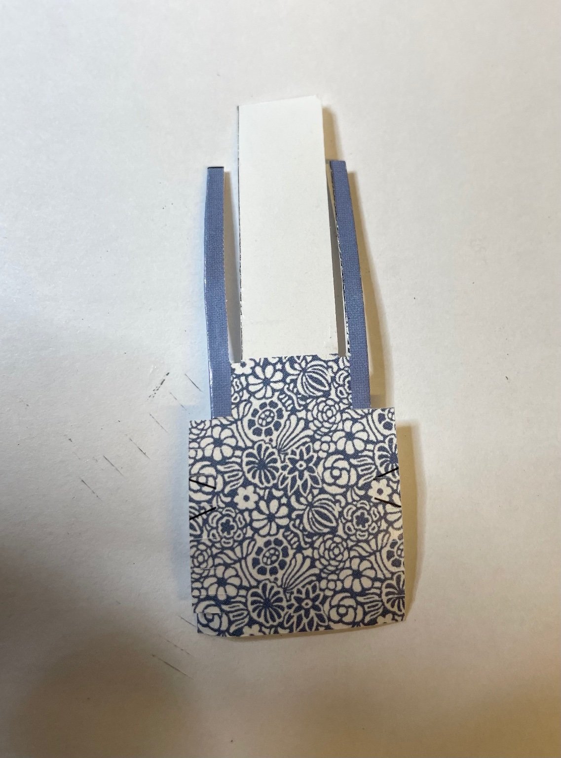
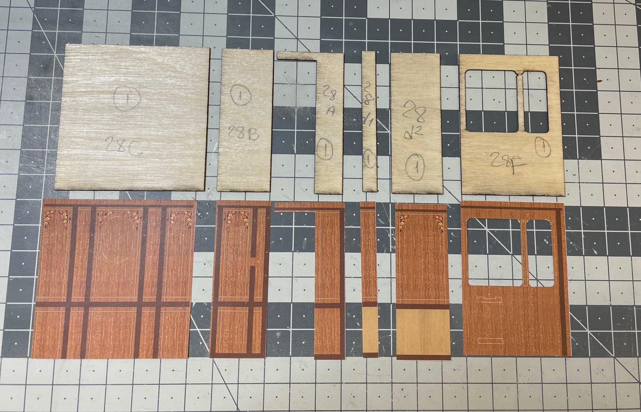
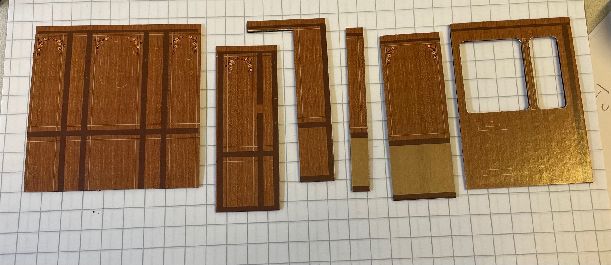
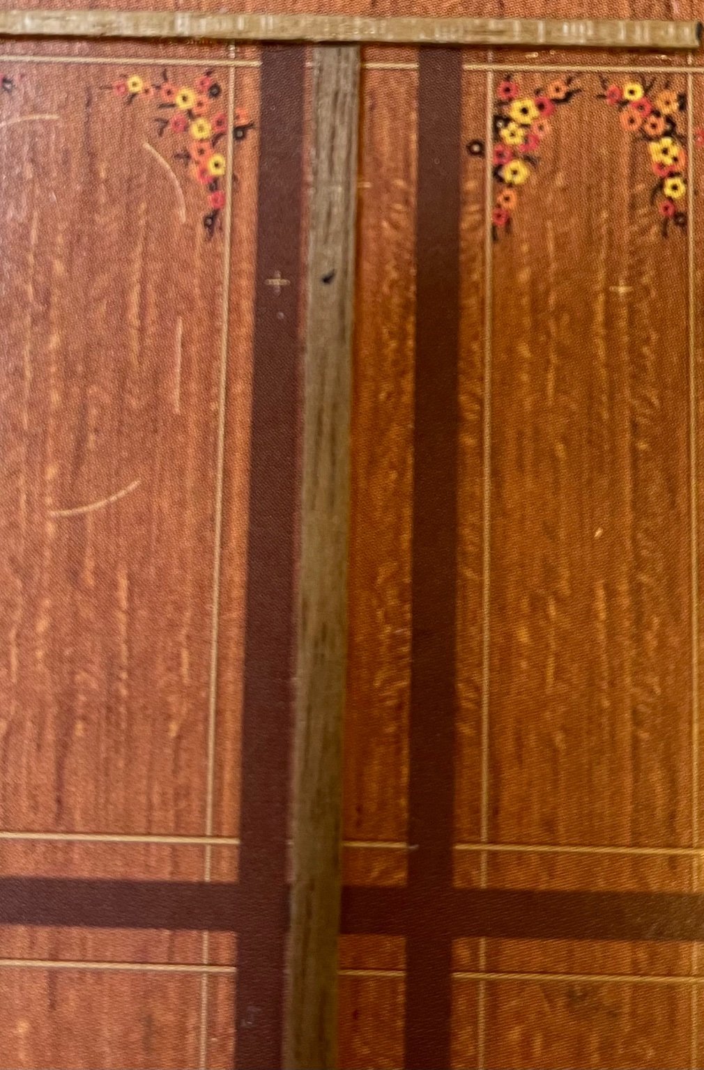
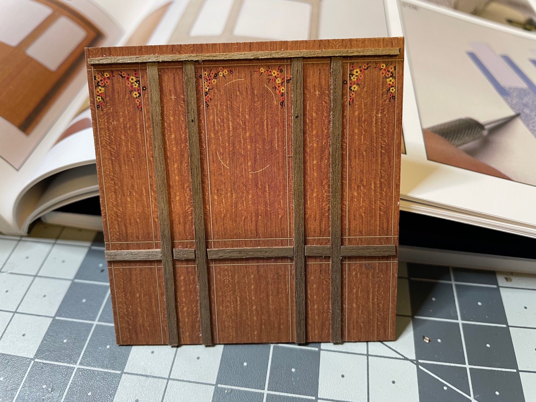
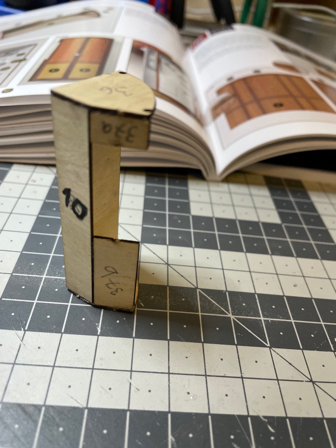
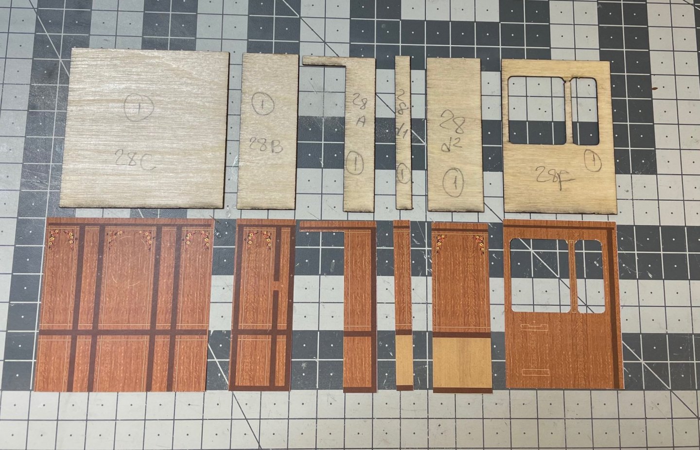
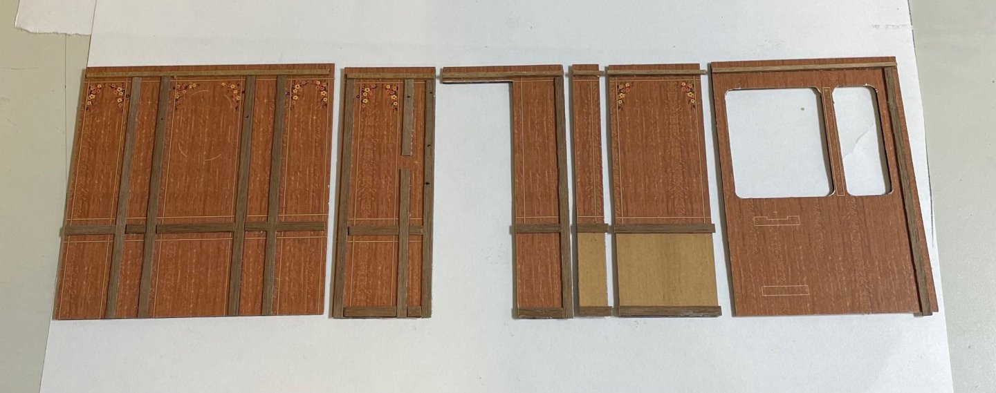
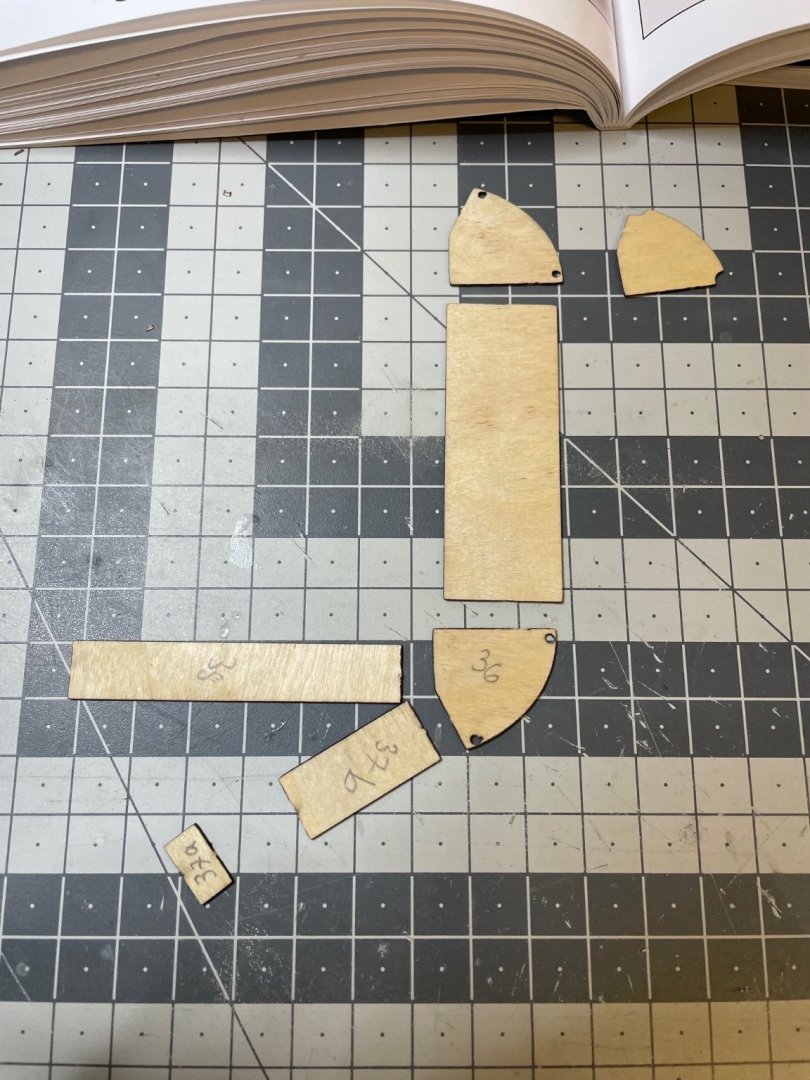
BUILD DAY 16 / 2 hrs / (TOTAL: 42 hrs) Bathroom cabinets have been put side now and it is time to start building the inner walls. Starting with compartment #1. Figure 178: Here again all pieces must be carefully numbered as they are quite similar yet slightly different at each compartment. Top row: plywood sheets. Bottom row: Matching paper prints. Figure 179: Papers glued. I used white glue all the way, applied using a brush. Figure 180: Paper print has several small marks indicating where the accessories will be glued later. Some of these marks remain under the wood lining, therefore you'll need to mark them on the corresponding spot on the wood strip before gluing them, like in this picture. Figure 181: First wood linings glued. NOTE: These are supplied in walnut. According to the instructions they should be stained in mahogany color. I don't know why Amati did not supply them in mahogany at first place. Cost? Most probably. Or maybe they are not available in mahogany in these sizes (1x1 mm and 0.5x2mm). I first thought of leaving them as walnut but then for the sake of precision I ran to the hobby shop and bought mahogany color and also some mahogany strips. The strips are 0.7x2mm and with a little sanding will fit just fine for 0.5x2mm purpose. For these ones in the photo (as well as the walnut strips on the bathroom doors) and 1x1mm strips I will use the mahogany paint. Figure 182: Walls of compartment #1. Note that some of the horizontal wooden strips exceed the edges by around 1mm. They are needed for corner turns. The walls are put aside for now. Some components, such as the headrests, will be installed before the walls are mounted in their places. By the way there are a lot of "build and put aside for now" in building this kit


- 293 replies
-
- 10
-
-
Thanks Ken!
-
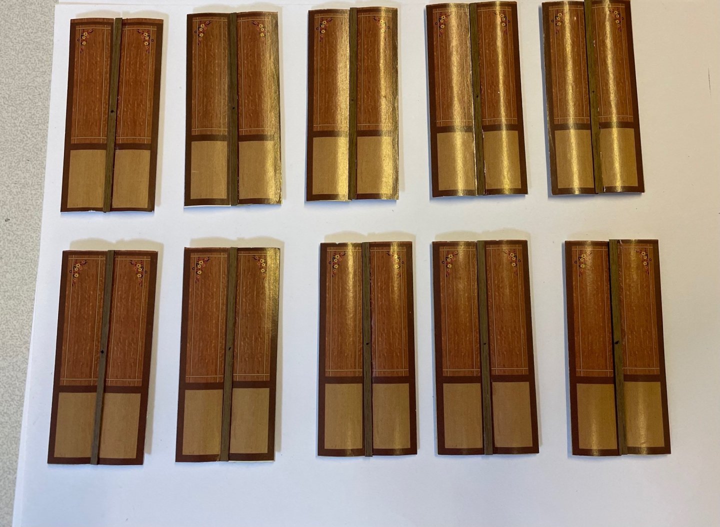
Figures 176, 177: Doors installed and the handles have been glued. They are now to be put aside until later. I have cropped the excess of the hinges (i.e. the copper tube sticks) from the bottom in order to stand straight. I will crop the excess on the upper parts after I have installed them in their place.

- 293 replies
-
- 14
-
-
Figure 175: All the accessories in place for all the bathrooms. Here is one example. Next in line will be installation of the doors. That's all for today! Thanks for watching!
- 293 replies
-
- 10
-
-

-
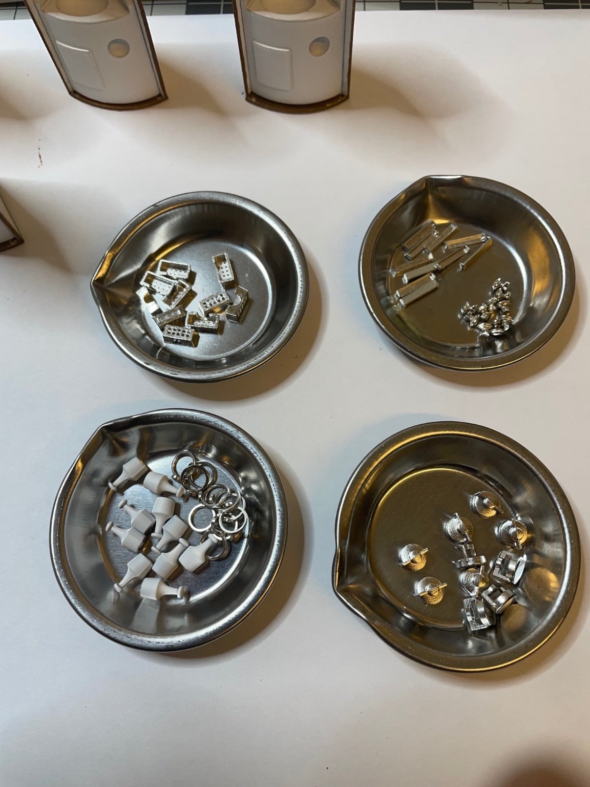
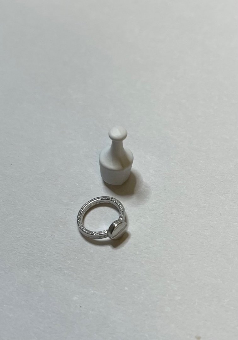
Figure 174: This is a real annoyance, especially in this kind of a high quality and pricey kit: Bottle holder is too wide for the soap dispenser. 😡 Normally the task is supposed to be as easy as gluing the holder on the wall and then dropping the bottle into it and the bottle should just stay. However now the bottle passes through the ring. This should not happen. Now I have to glue the bottle to the ring from a touch point.
-
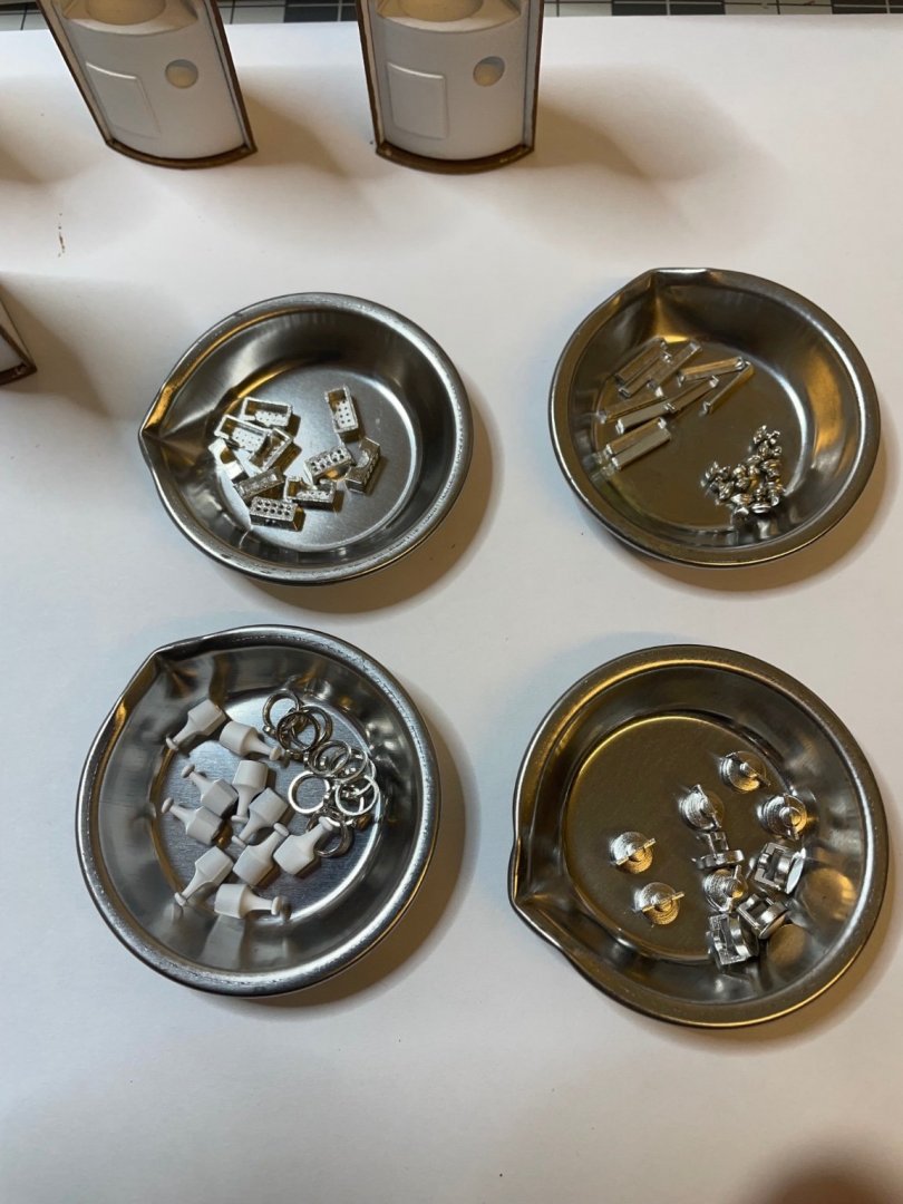
Figure 173: Bathroom accessories sorted, ready to glue in their places.
-
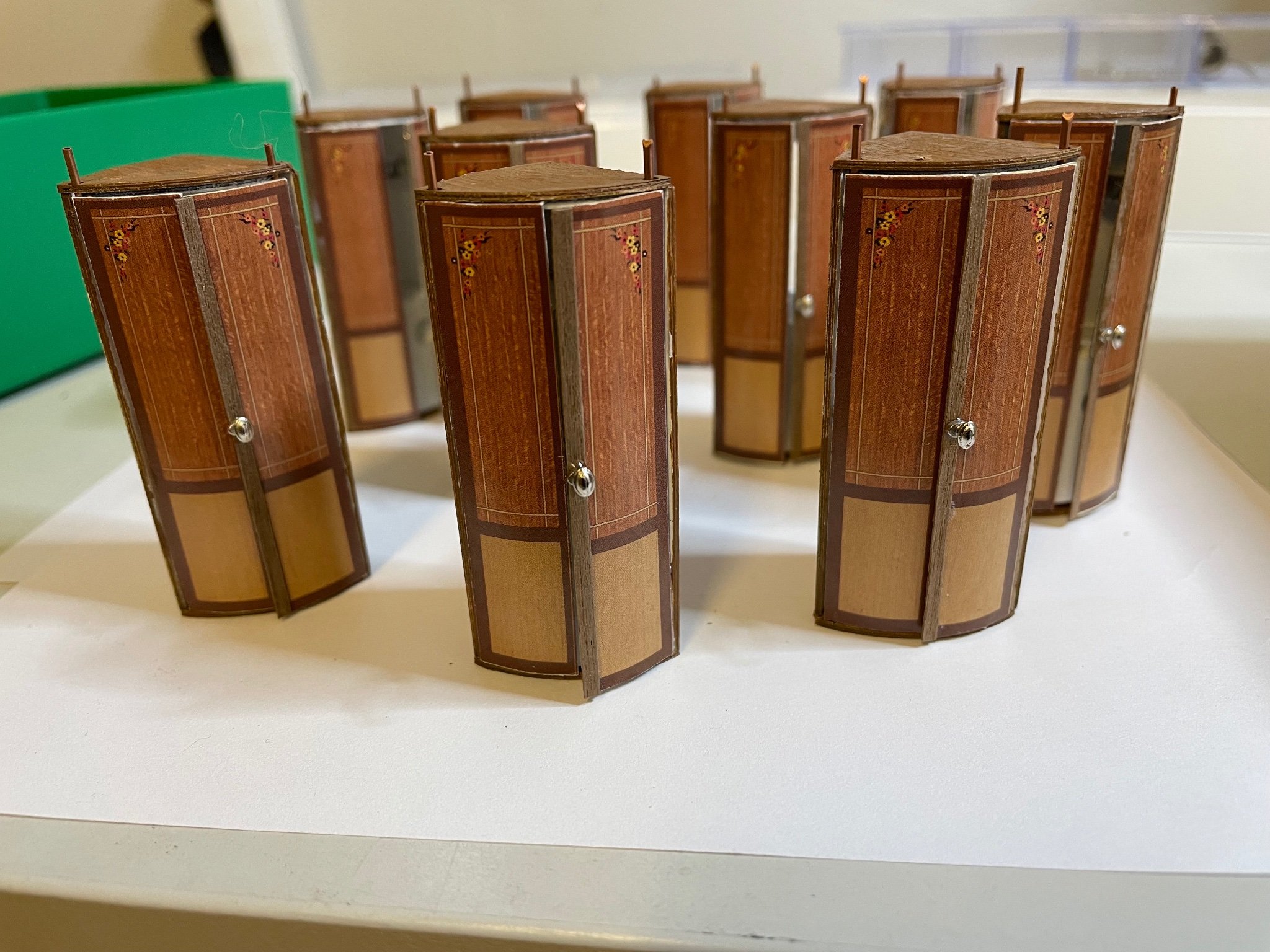
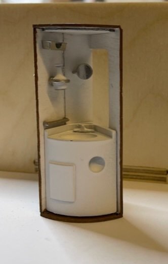
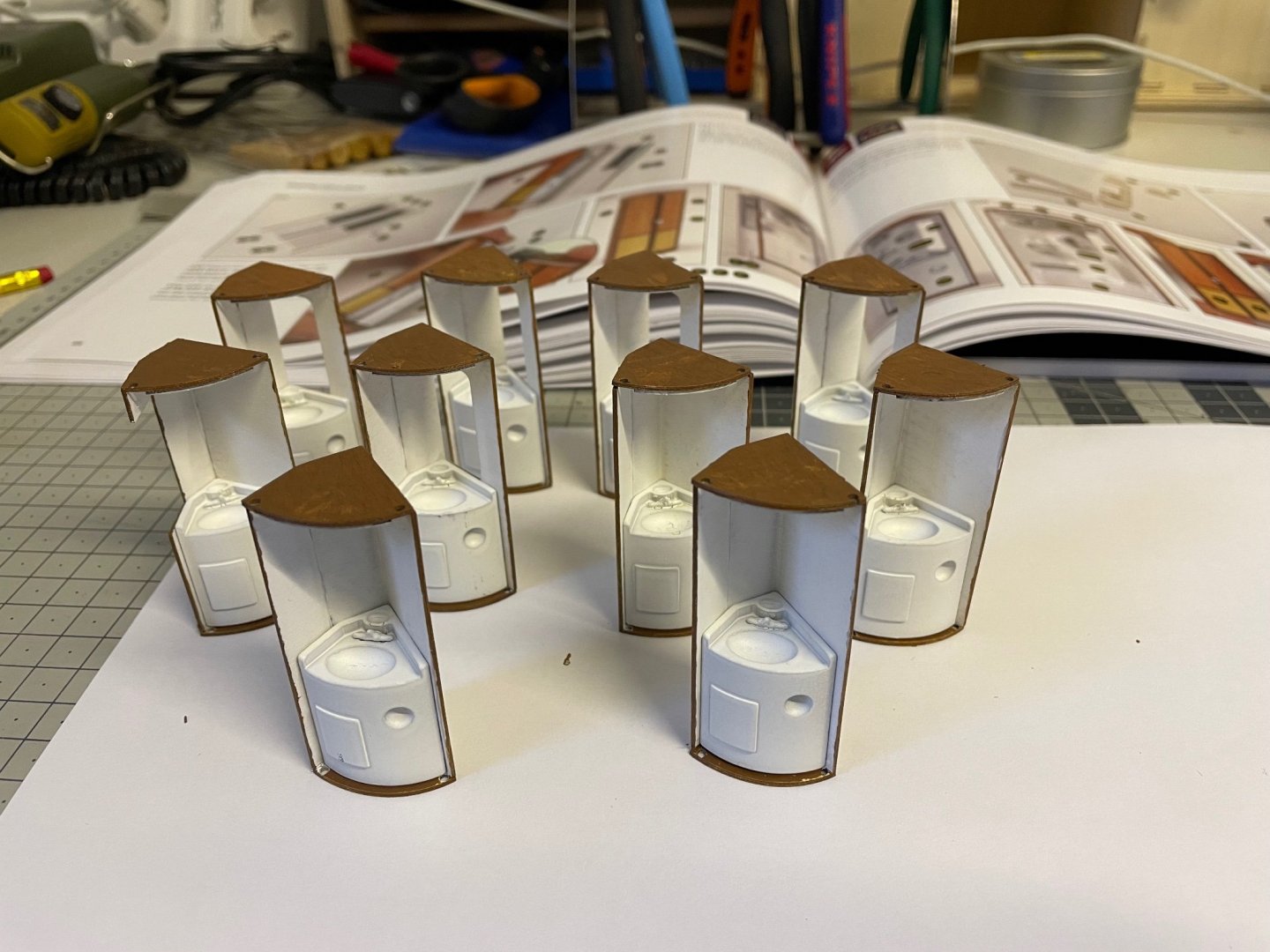
Figure 172: All 10 bathrooms with wash basins glued.
-
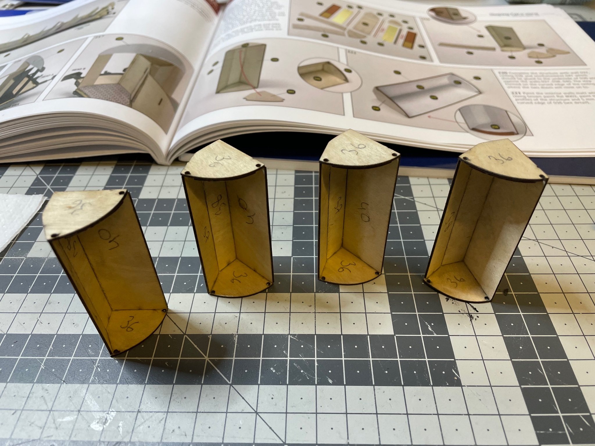
Figures 170, 171: Bathroom of compartment 10. This one is slightly different from all the others. By the way, all the bathroom cabinets have the same accessories, but because of the slightly varying shapes of the cabinets, their placement on the walls will differ.

-
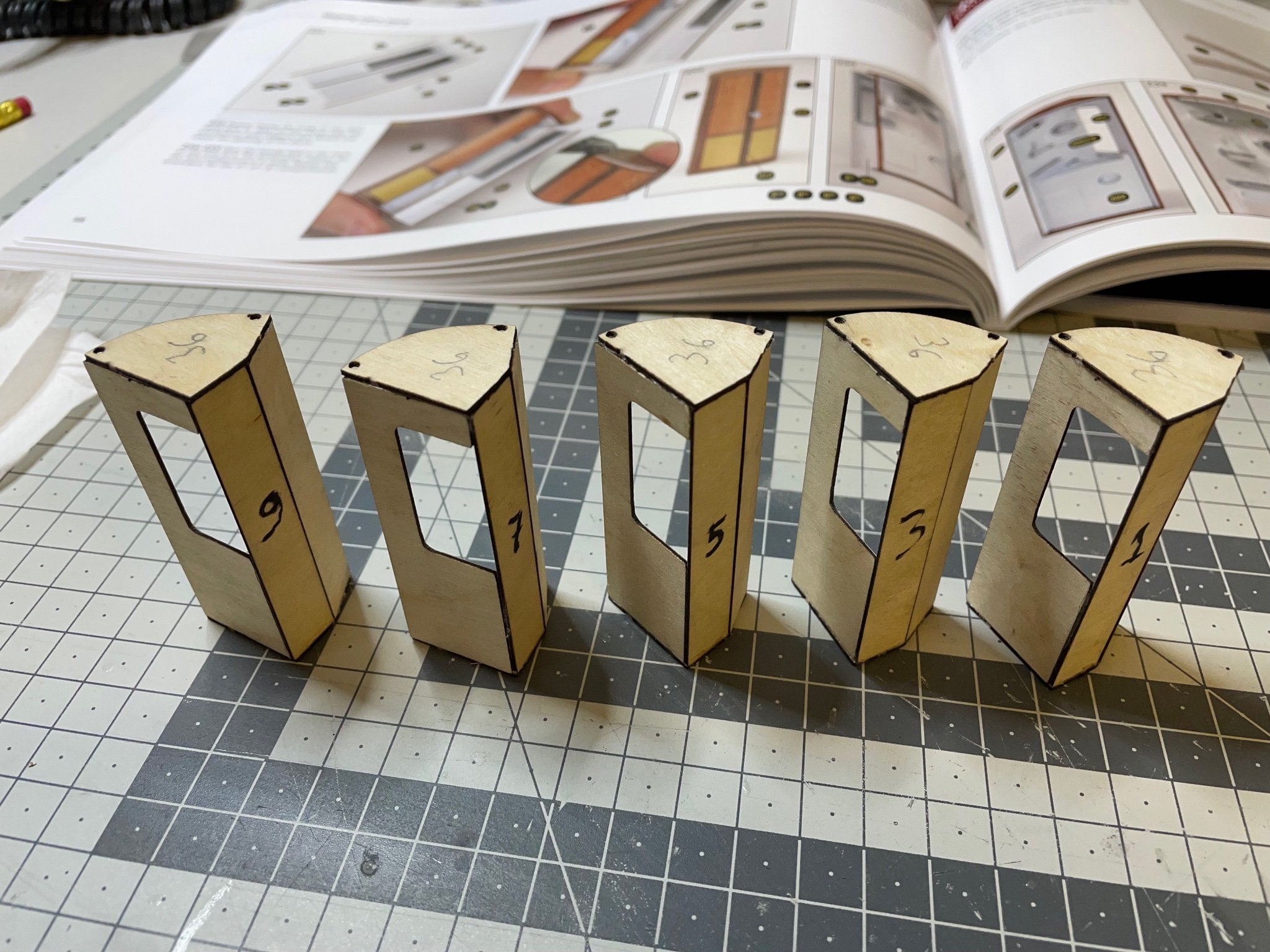
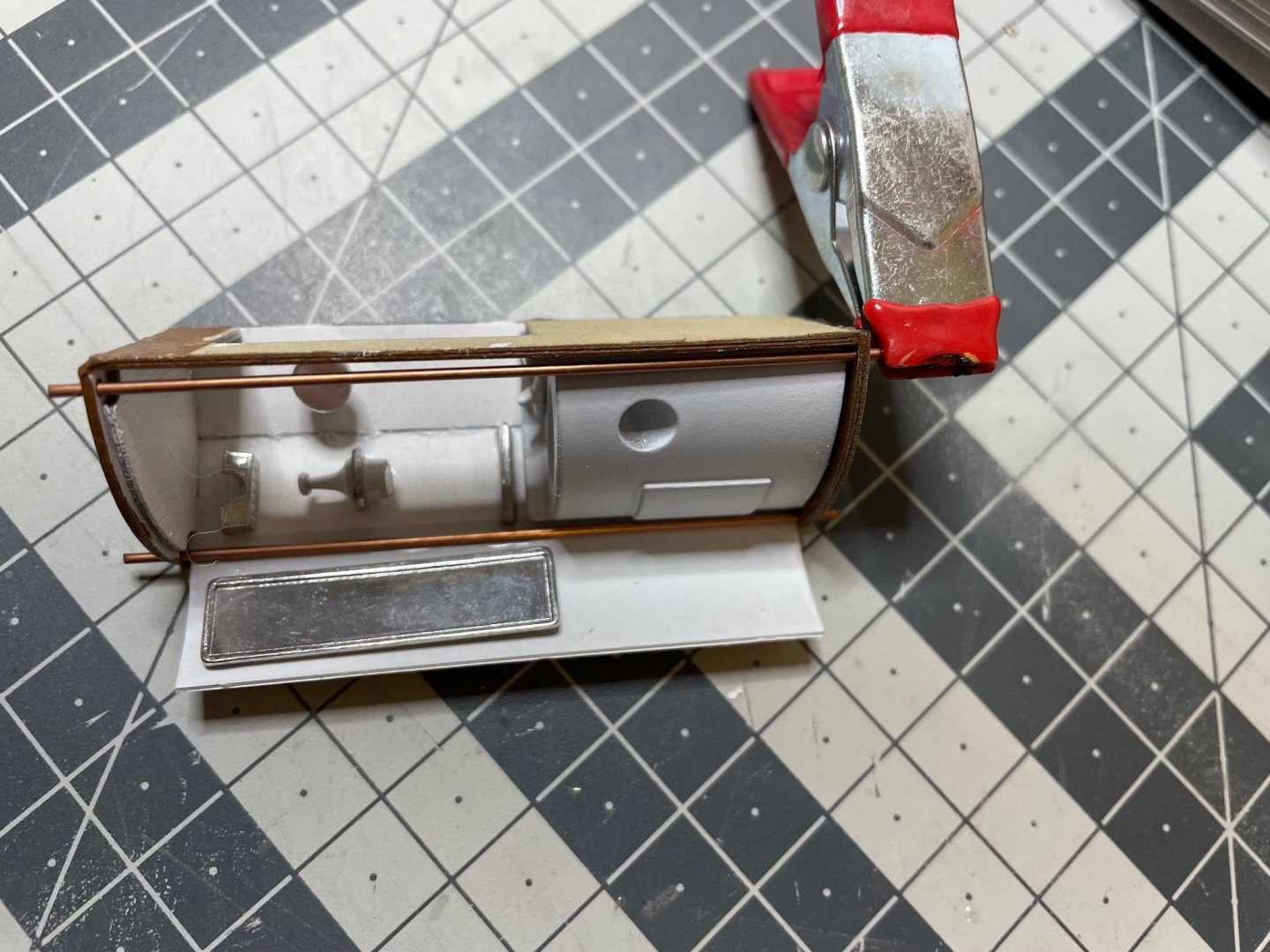
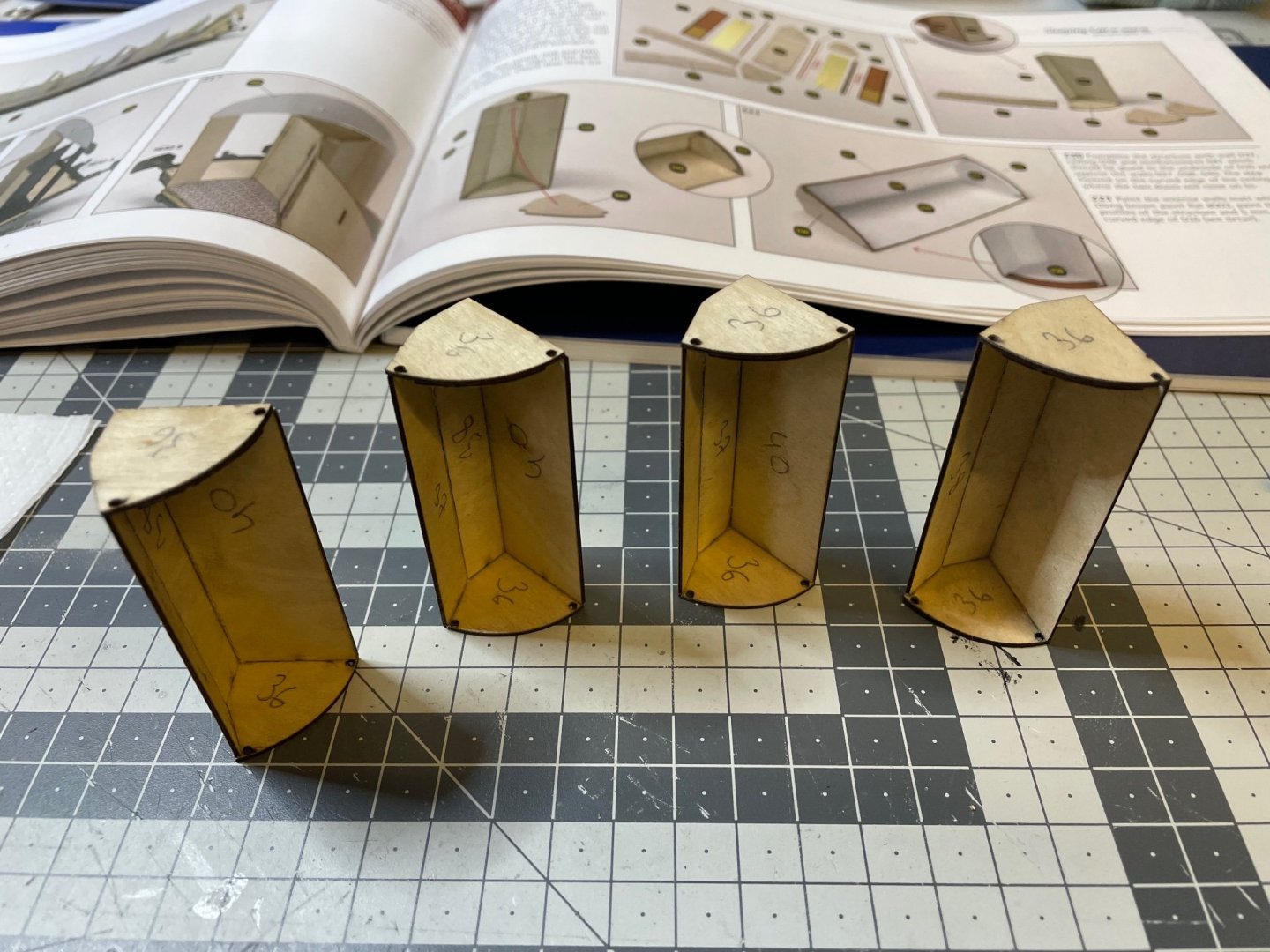
BUILD DAY 15: 4 hrs (TOTAL: 40 hrs) Continuing with structures of the rest of the bathroom cabinets. Figure 169: Bathrooms for compartments 1,3,5,7 and 9. Note they differ from the previous ones with a window on opening on one side.

-
Interesting information, thanks for sharing. I didn't know they had soap dispenser back then.
-
Figure 168: Doors ready, though not fully. They are missing handles and the hinges. That's all for today! Thanks for watching!
- 293 replies
-
- 13
-
-
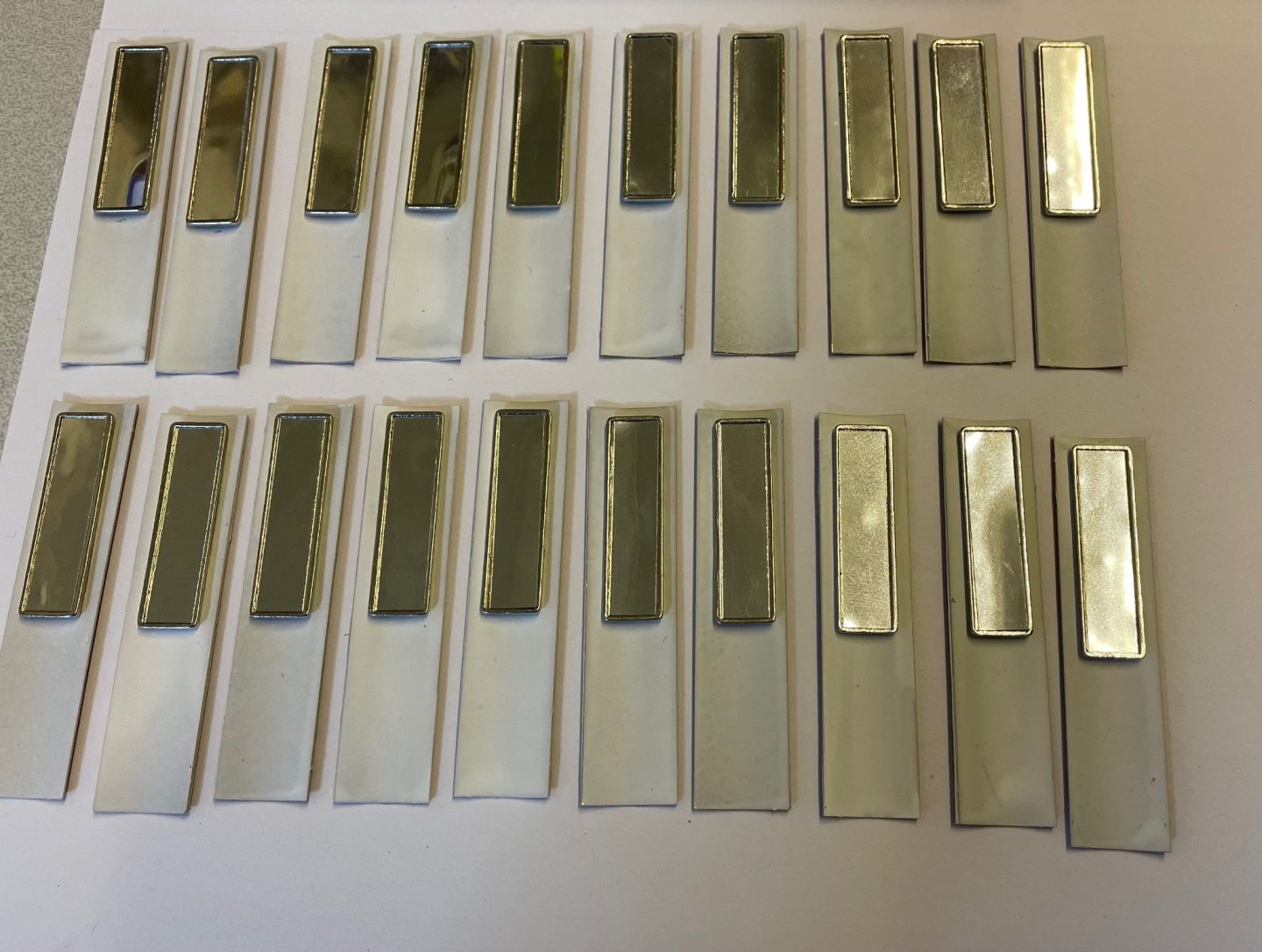
Figures 166, 167 : Mirrors on both door wings. Note also the wooden trims with an offset on the right door wings. When the doors are closed, this offset will overlap with the edge of the the left wing.

- 293 replies
-
- 10
-
-
Figure 165: At this stage I applied white stationary glue with a brush for gluing the paper.

-
Figure 164: There is a + mark on the paper decorations indicating the location of the door handle. That mark is to be transferred on the wooden trim. The handle will then be glued on the wooded trim.
- 293 replies
-
- 10
-
-
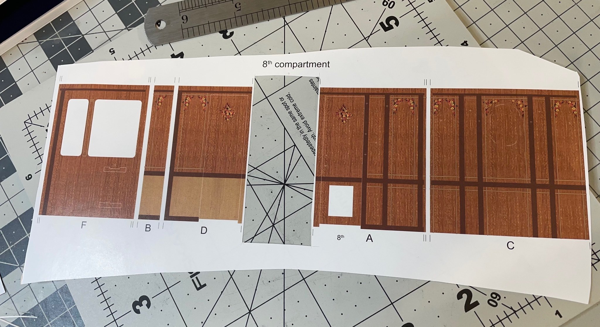
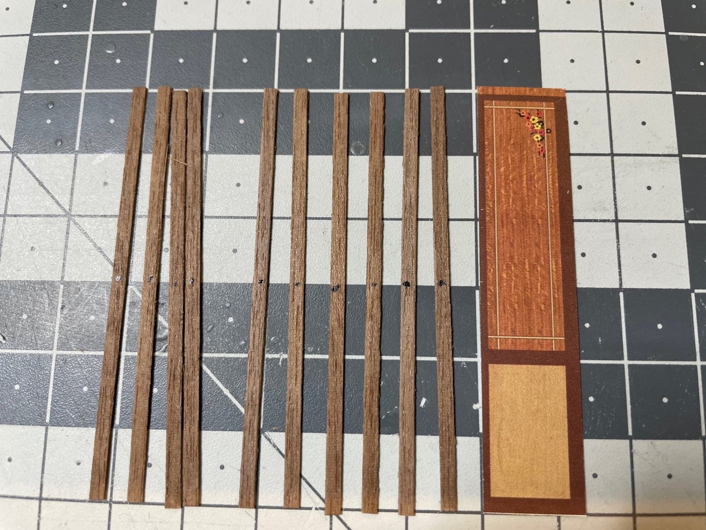
Here is how I always keep the paper sheets intact, removing only the part needed, so that I can identify the parts. In this case I know that this sheet belongs to compartment 8, as well as the labels of each piece (F, B .. etc). Figure 163

-
Figure 161: Doors ready for painting their inner side. The instructions address to glue the paper decoration outside first and then paint inside, but I see it too risky. Paint will definitely leak on the back surface. There should be no paper decoration at that time. Figure 162: Doors painted matt white.

-
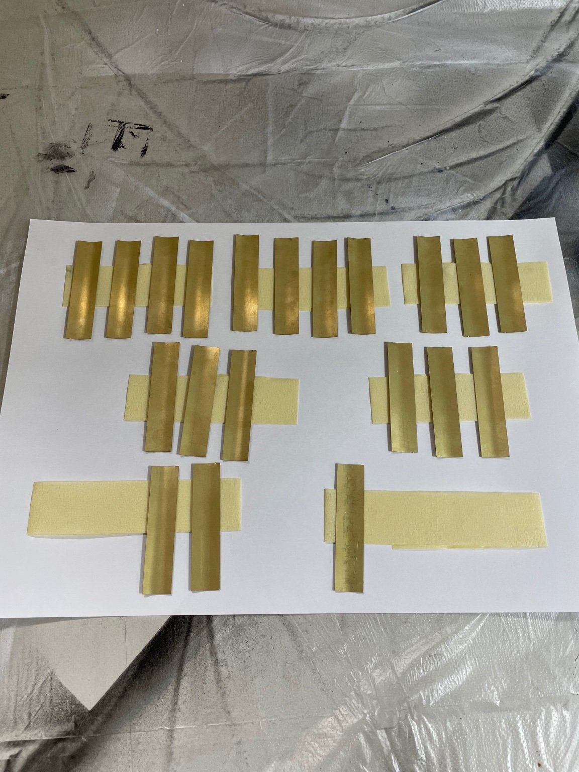
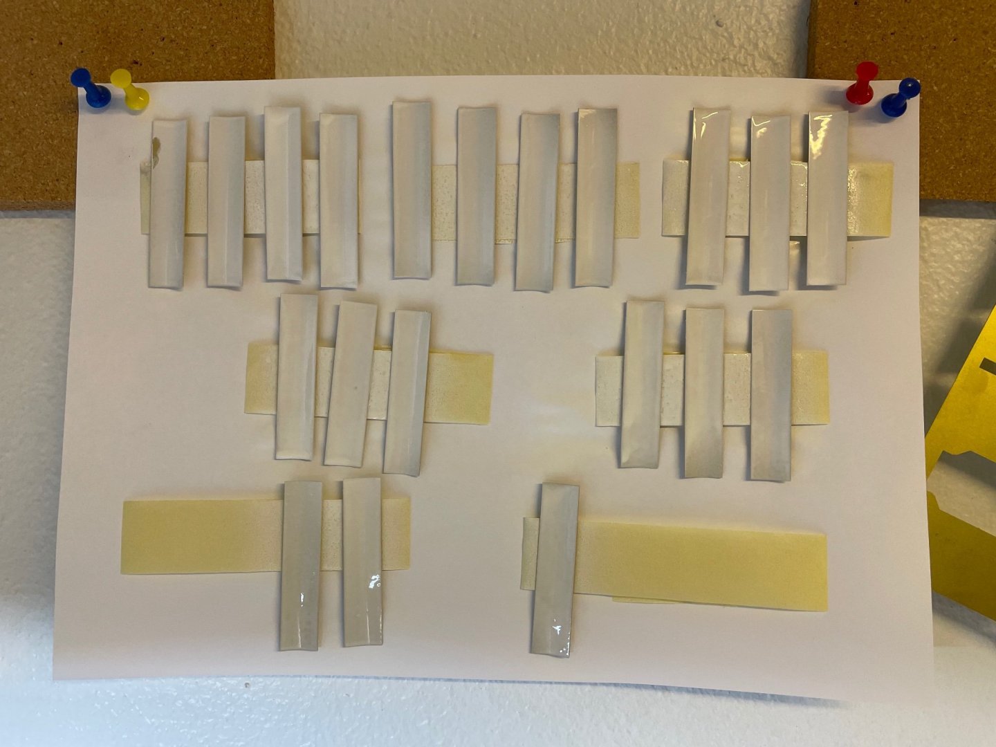
Figure 160: Here are all 20 doors curved.
-
Figure 159: The result looks good for the first one. It fits the cabinet nicely.

-
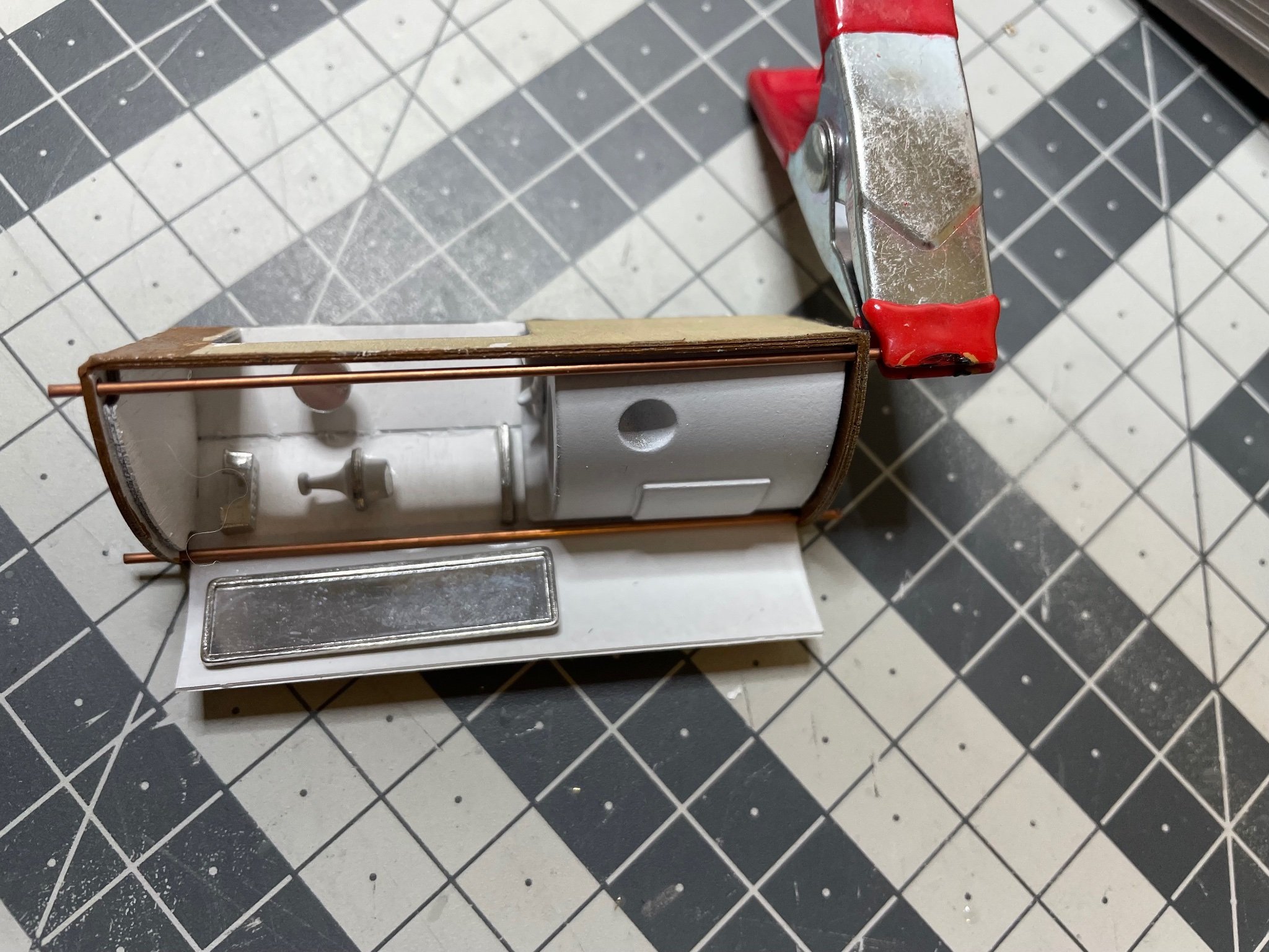
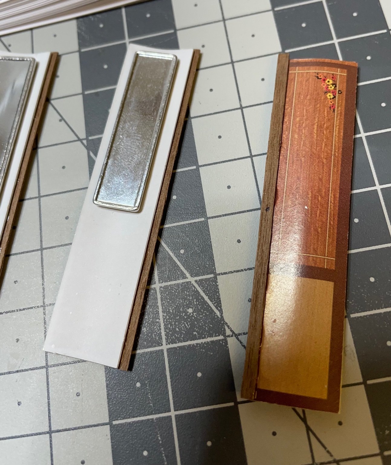
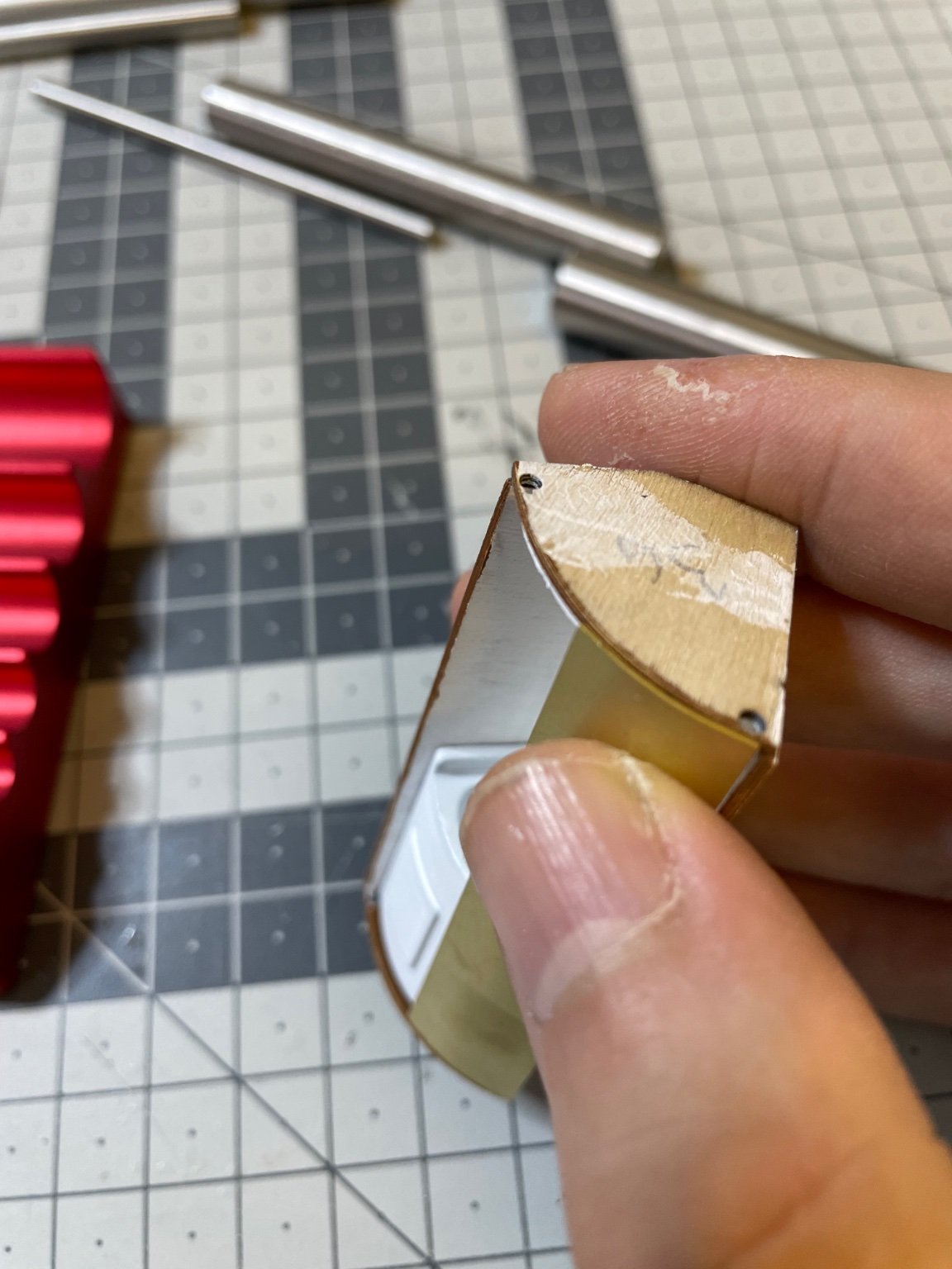
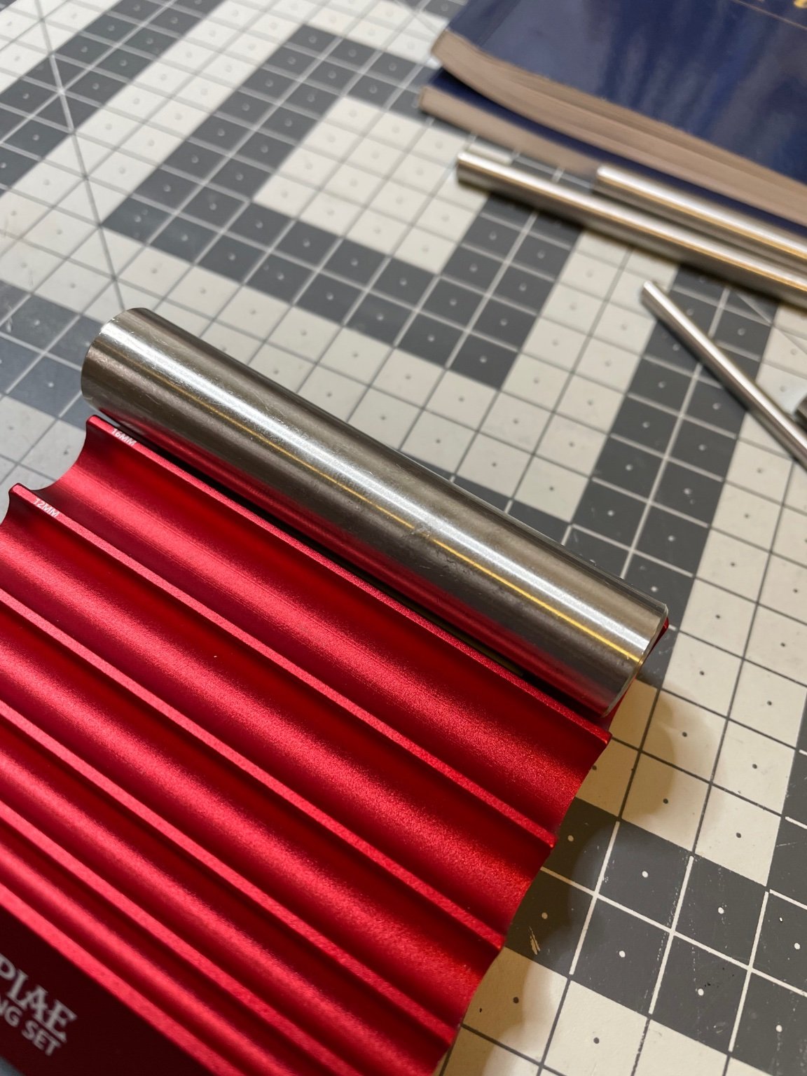
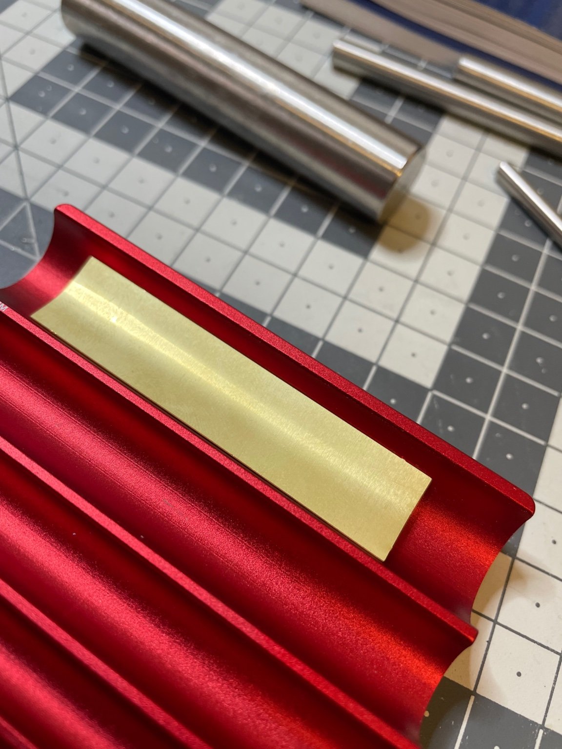
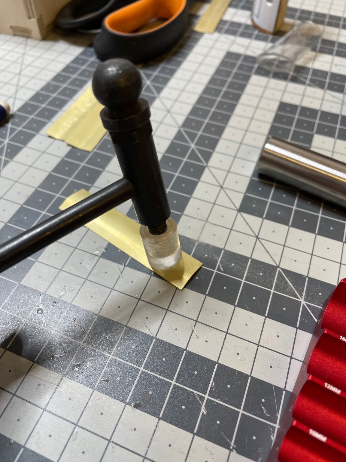
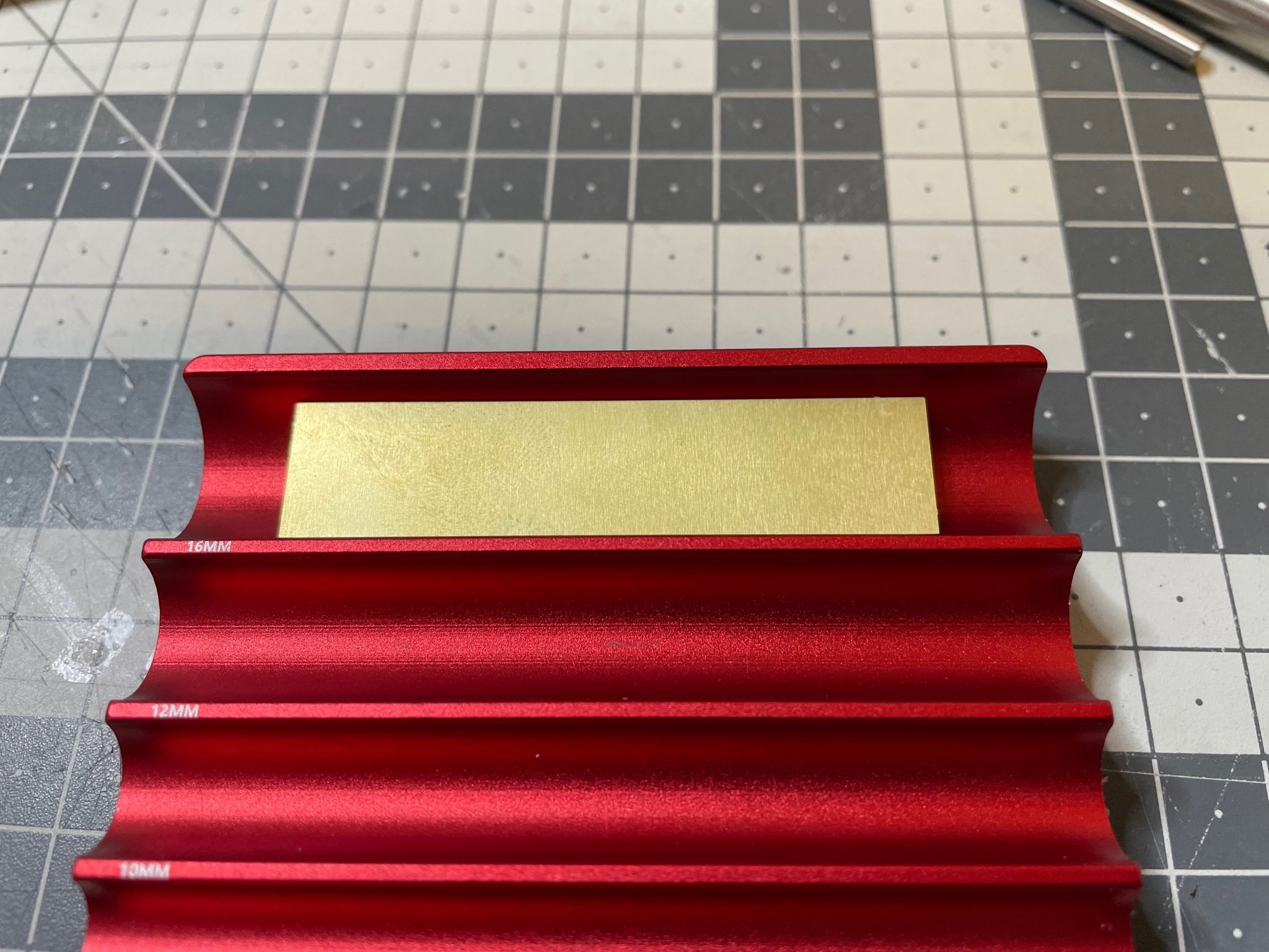
Bathroom doors. One pair per bathroom. They are made of 0.4mm photo etched brass, to be bent to match the curvature of the bathroom cabinet. The bathroom doors are identical regardless of the cabin numbers therefore I build all 10 at once. Figure 155, 156: I use my DSPIAE photo etched roller for this purpose. I tried first with a scrap piece of same thickness and decided to use the 16mm curvature. Figure 157: I press with my both hands on the steel cylinder as hard as I can. Figure 158: I over-bent the parts and then widened the curvature by soft hits with a hammer, until it aligns with the structure.


-
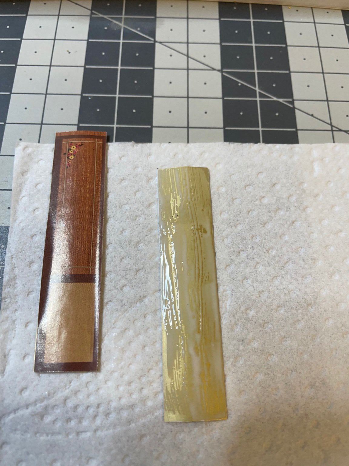
Figure 154: Painted inside matt white. Some brown trims will be put later.
-
Figure 153: Bottles (probably containing Eau de Cologne). They will be hanging on the wall above the sink.
-
Figure 152: The was basins. They are made of die cast metal. I paint them to white as instructed. I see some videos where the builder has painted the taps to silver color, but I will leave them white just like in the instruction manual. I haven't made a research but I guess they were more likely white porcelain, instead of metal. Look more elegant in white.
-
Figure 151: Basic structures of the bathrooms for cabins 2,4,6,8 are ready.
-
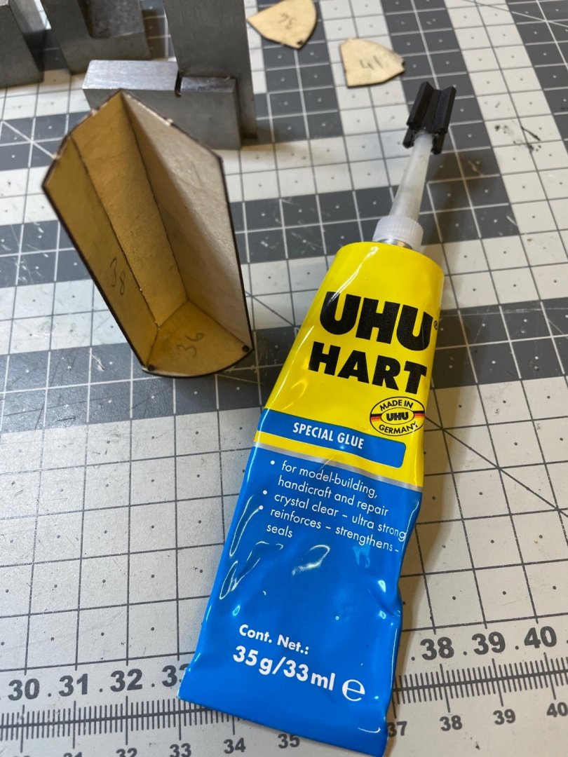
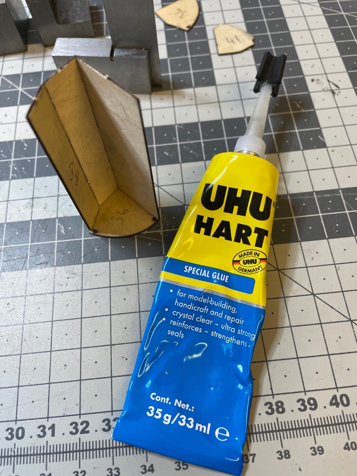
Figure 150: At this step I use UHU Hart, the pinnacle of German chemical engineering 🙂. My favourite modeling glue. Excellent stuff.