aydingocer
-
Posts
916 -
Joined
-
Last visited
Content Type
Profiles
Forums
Gallery
Events
Everything posted by aydingocer
-
 A good news today is from Amati. They have just dispatched the missing part from the box. It is a brass L profile for the sides of the body structure. Because of the lack of it I couldn’t proceed as planned, I had switched to building the bogies in the meantime. Now the bogies are almost ready and the package should arrive sometime next week, just in time to resume the body work. Thanks Amati.
 -
Thanks for the good tip, Yves! I will actually go through the entire painting details on the bogies once they are fully ready. There are many unpainted small parts as well as scratches caused by using tools. I’ll keep your points in mind then. I use acrylic paint hence removing it off the metal surface should not be a big deal, hopefully.
-
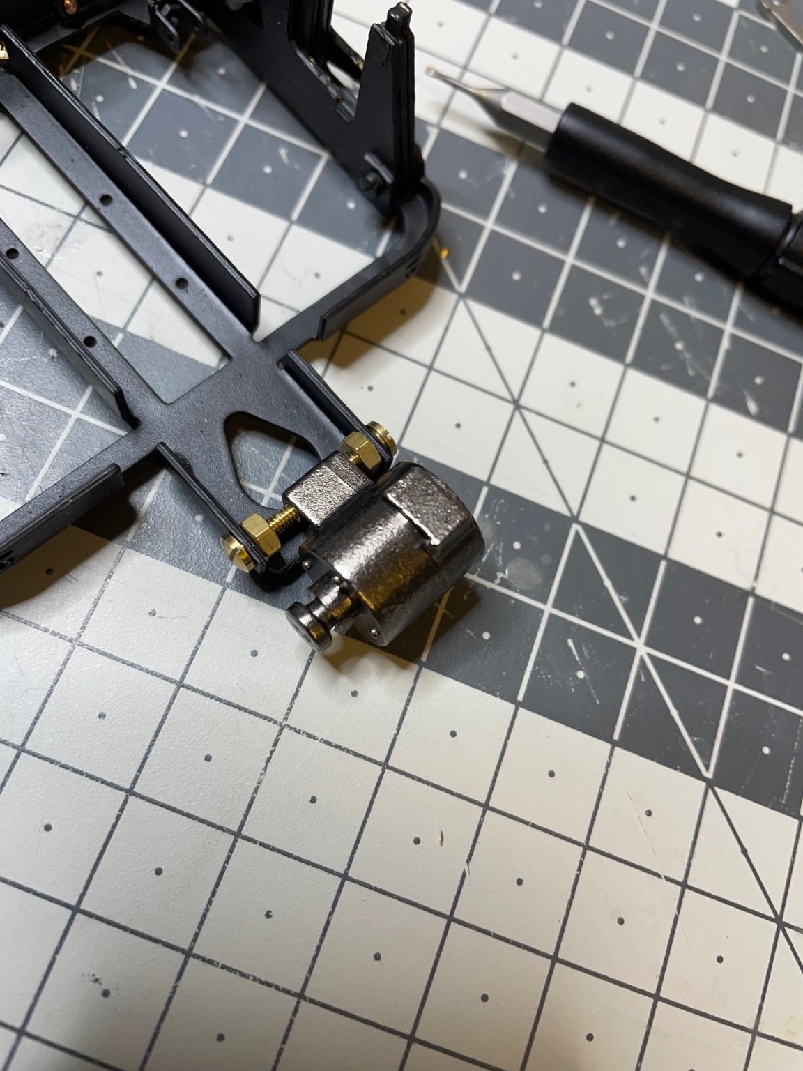
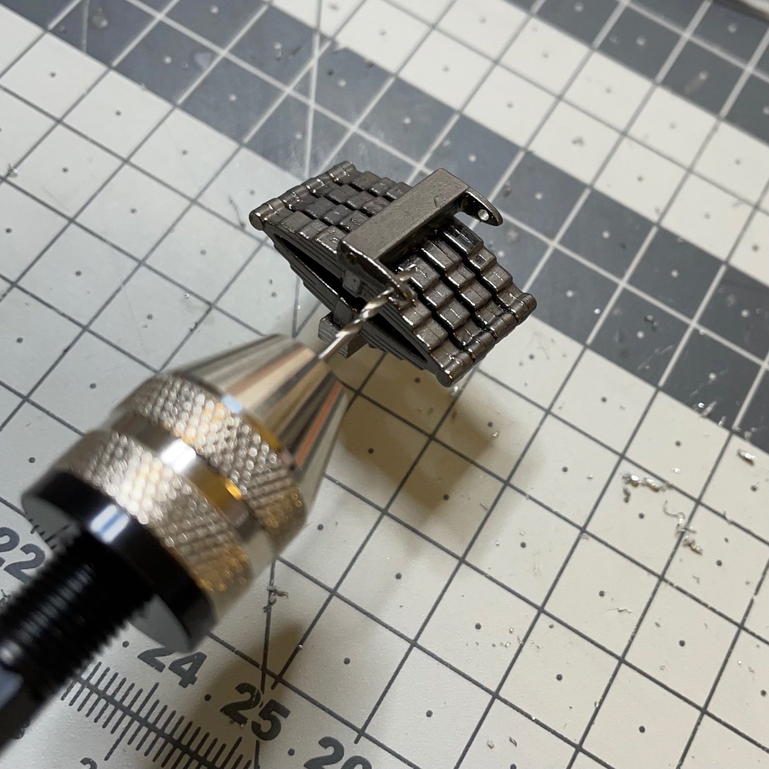
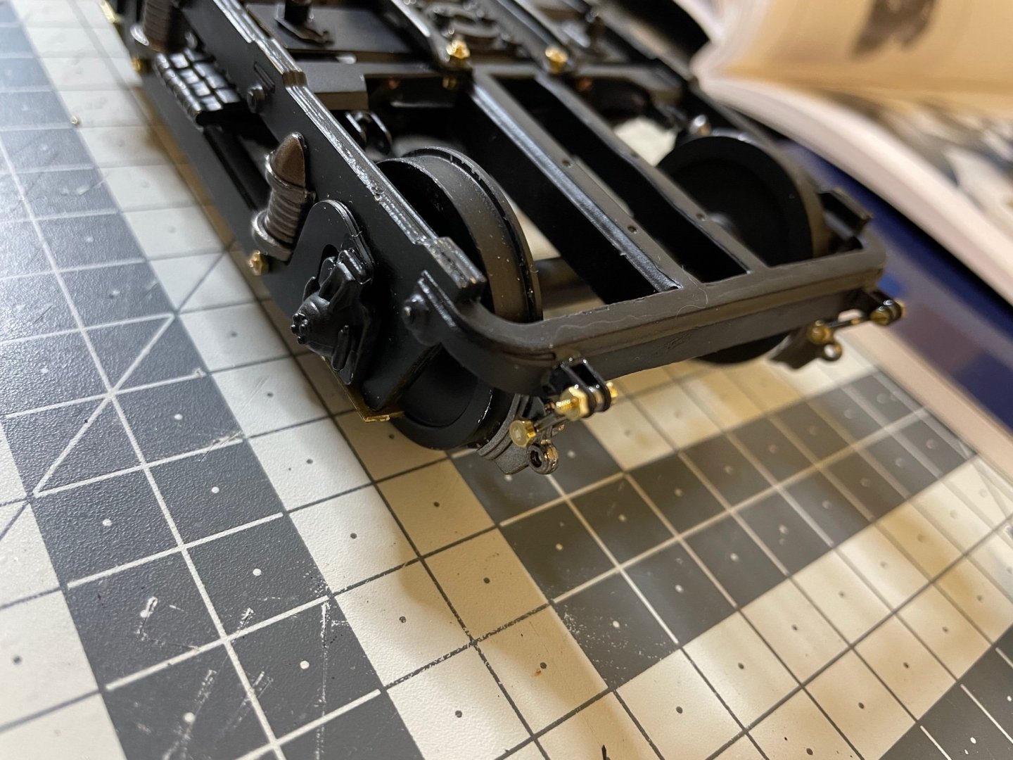
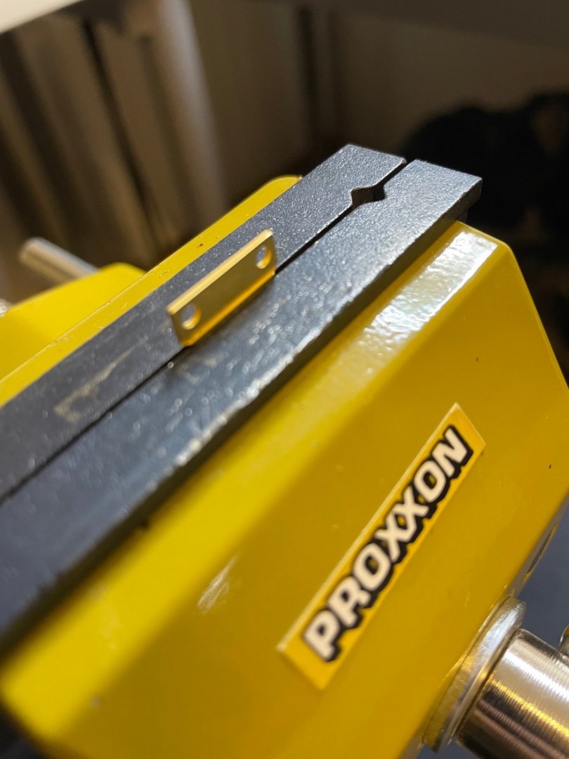
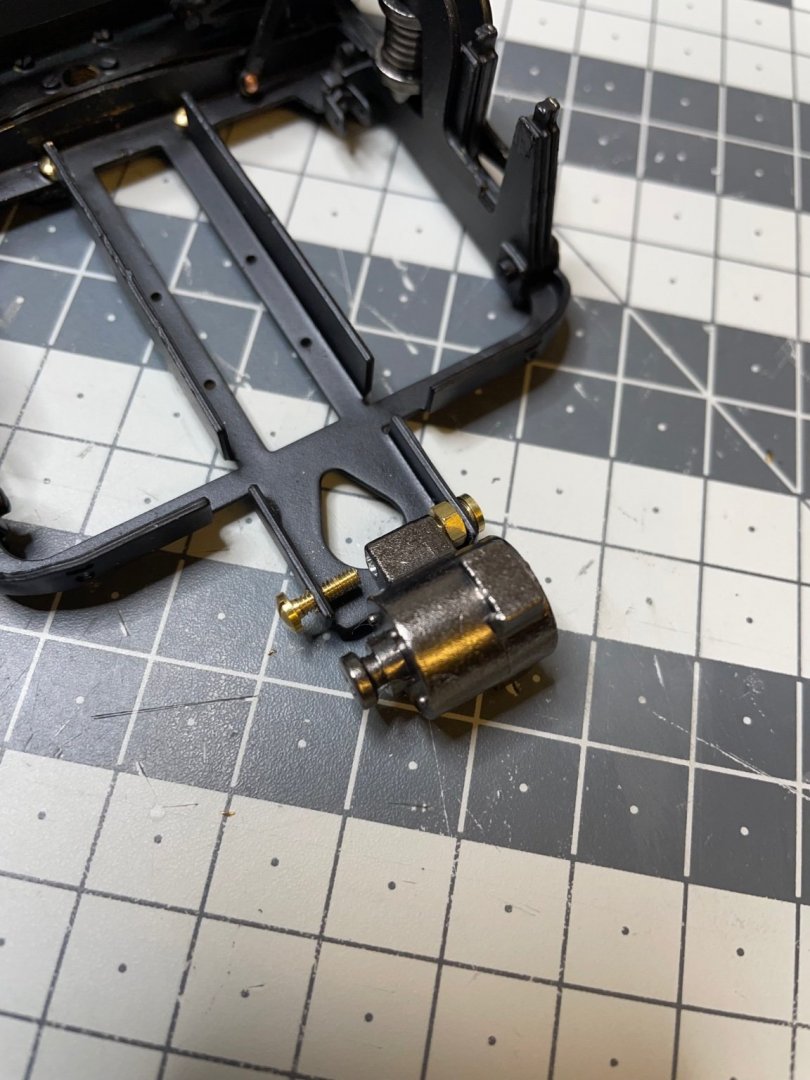
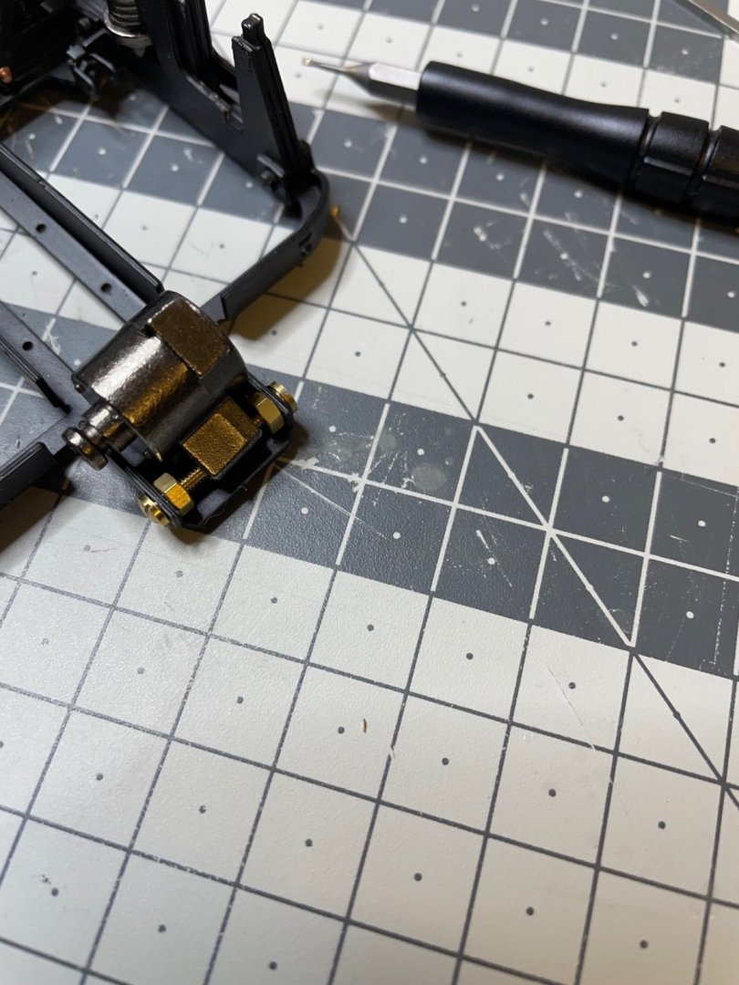
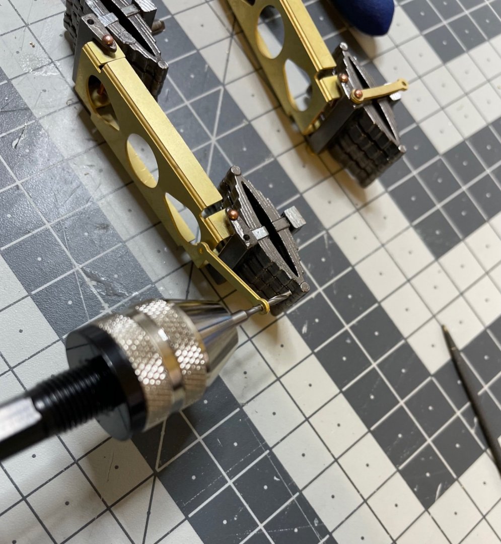
Figure 111: First brake shoe installed. When installed it swings freely on the bolt. I used superglue to fix it in position, just as close and parallel to the wheel. The brake shoes on the outer side are rather easy to install. However those on the inner parts are very very tricky to even fit at first place, let alone insert the bolt, tighten the nut and glue to the right position. My recommendation to a builder reading these pages would be to consider installing the brake shoes before installing the wheels. That's all for today! Thanks for watching!
- 293 replies
-
- 12
-

-
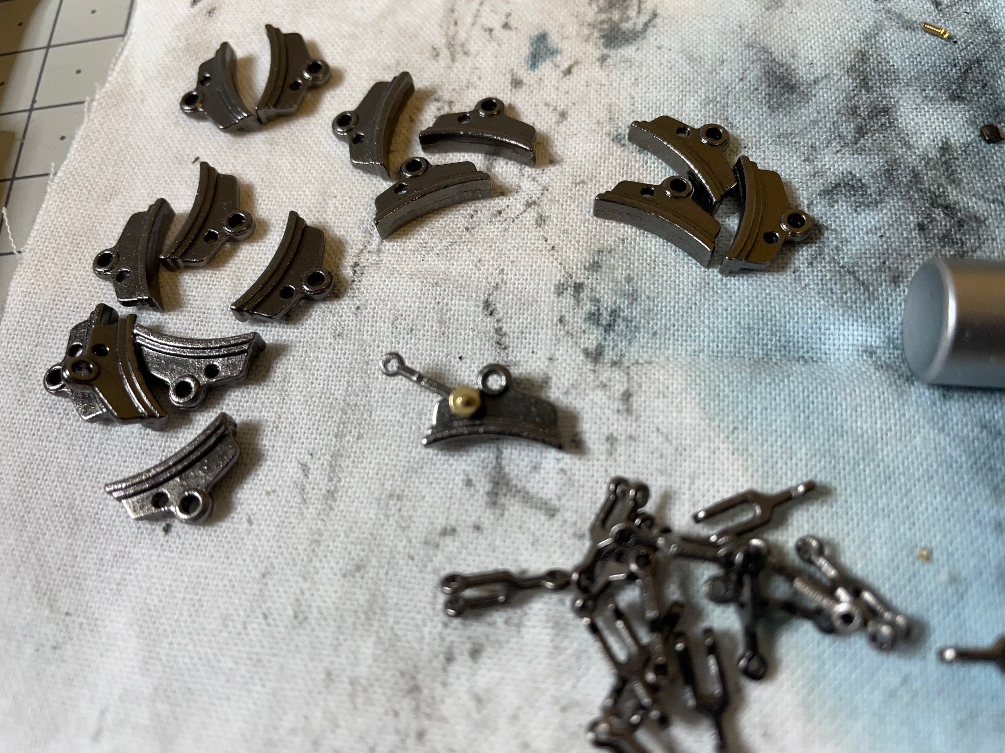
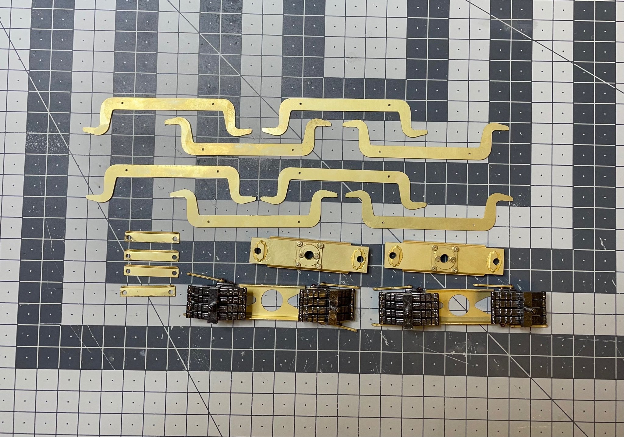
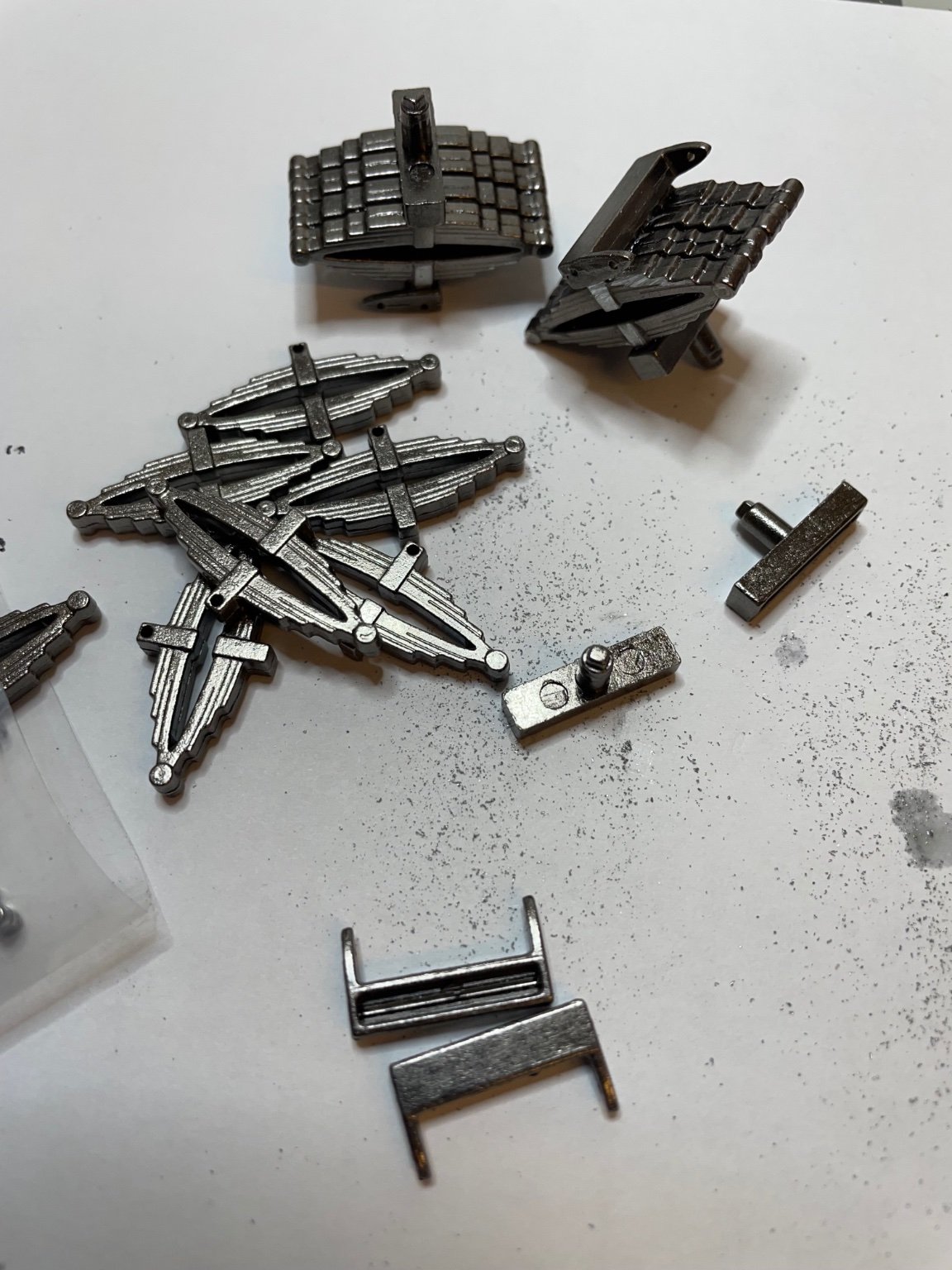
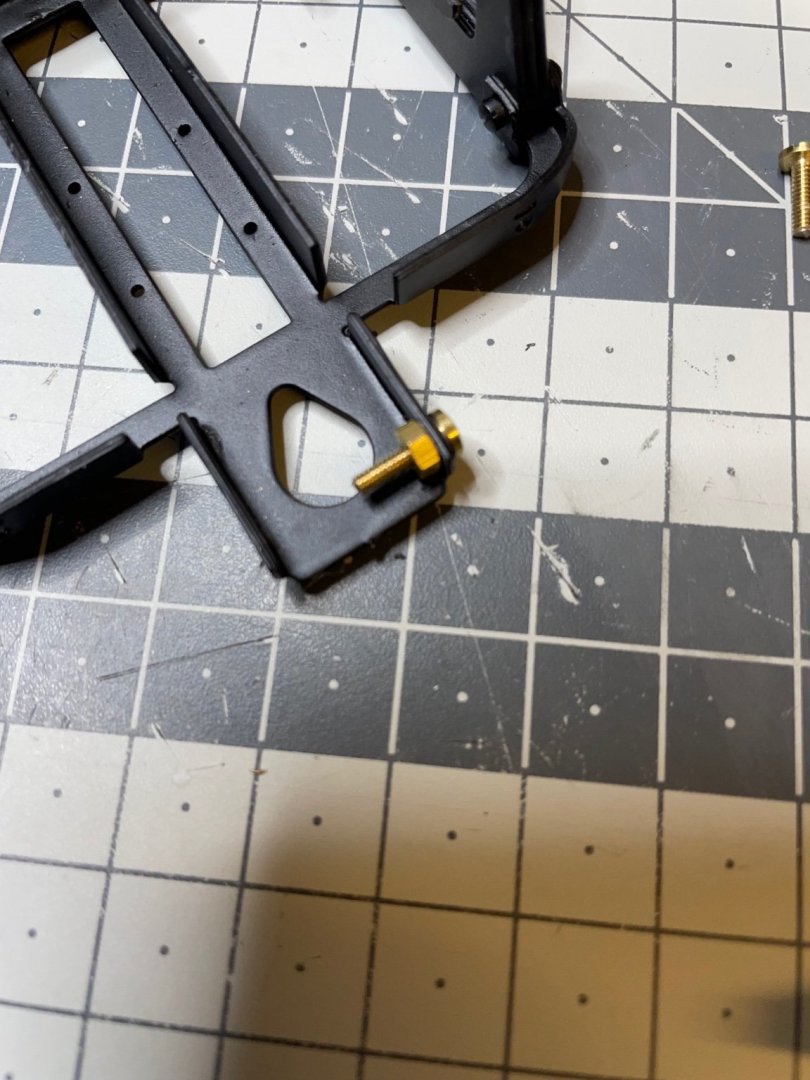
Figure 110: Brake shoes, consisting of two parts assembled with nut and bolt. There will be 16 of them, one pair for each wheel. In the middle you see one of them assembled.

-
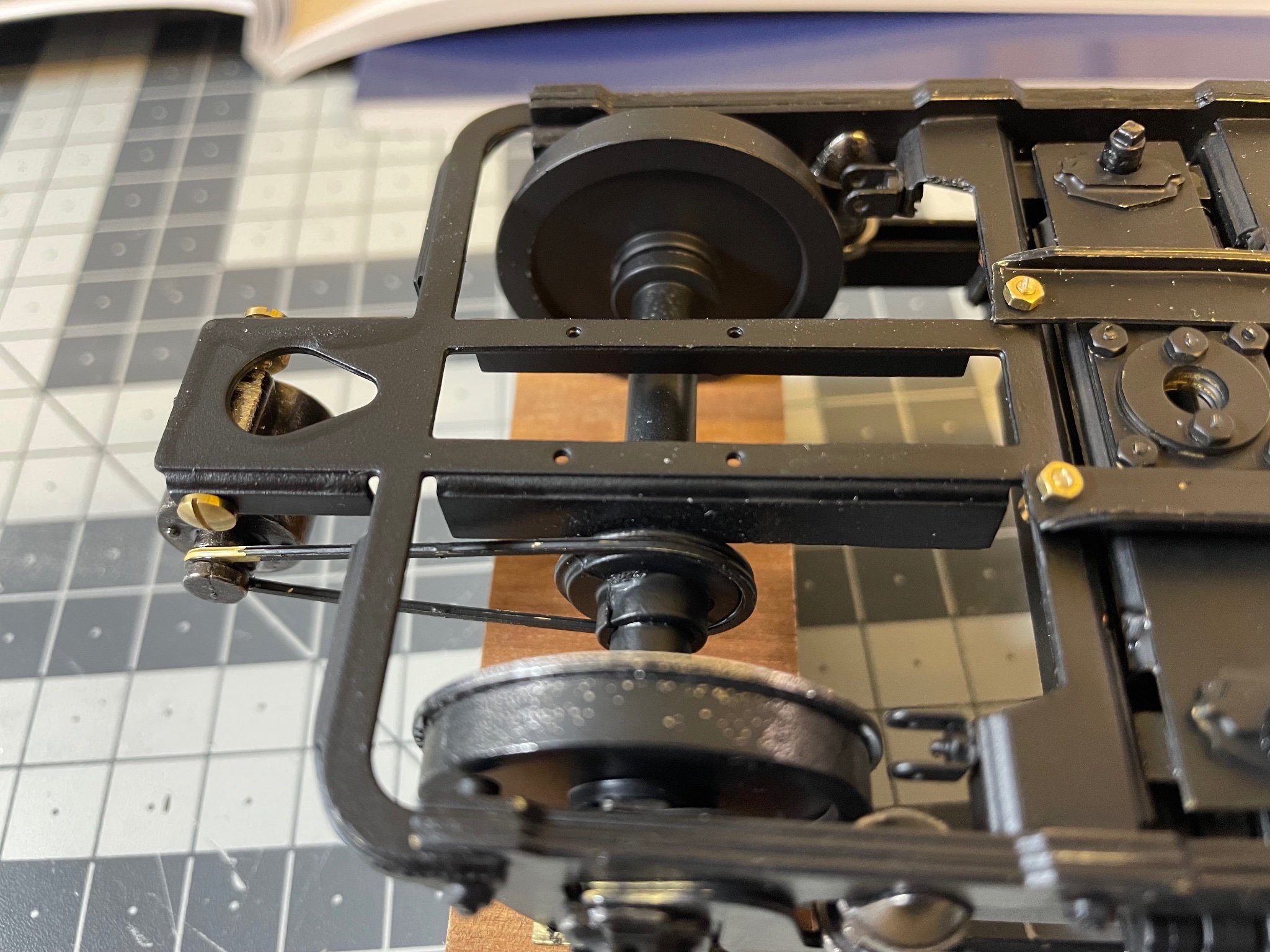
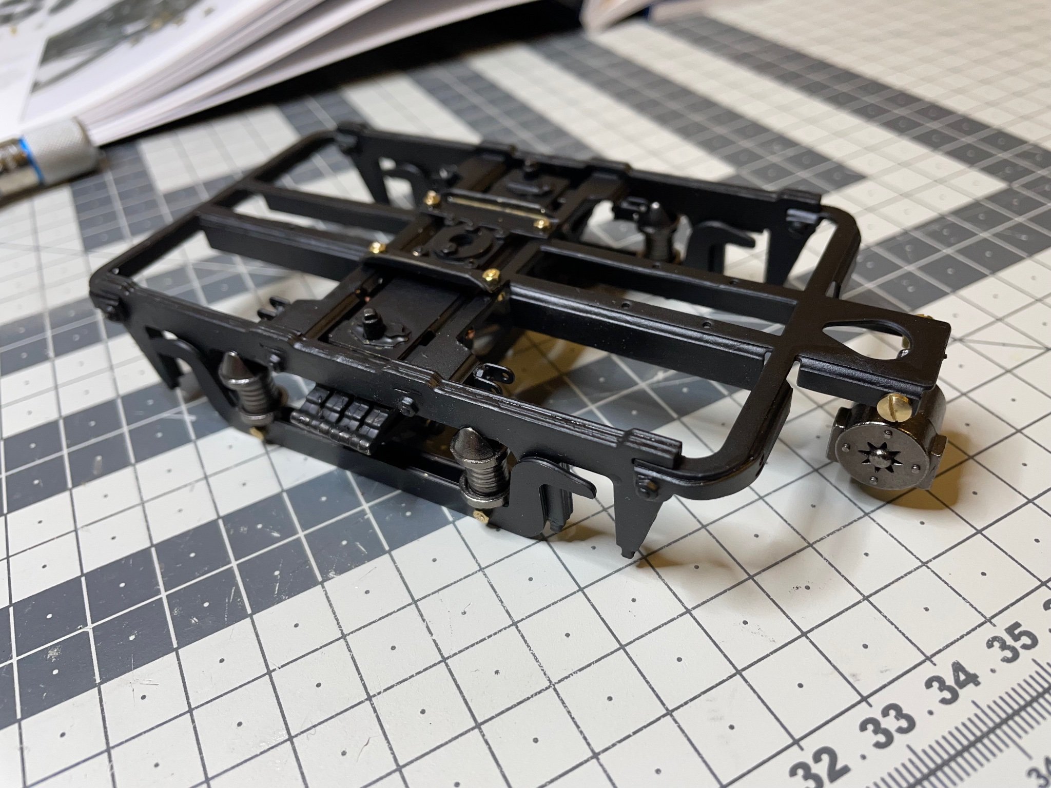
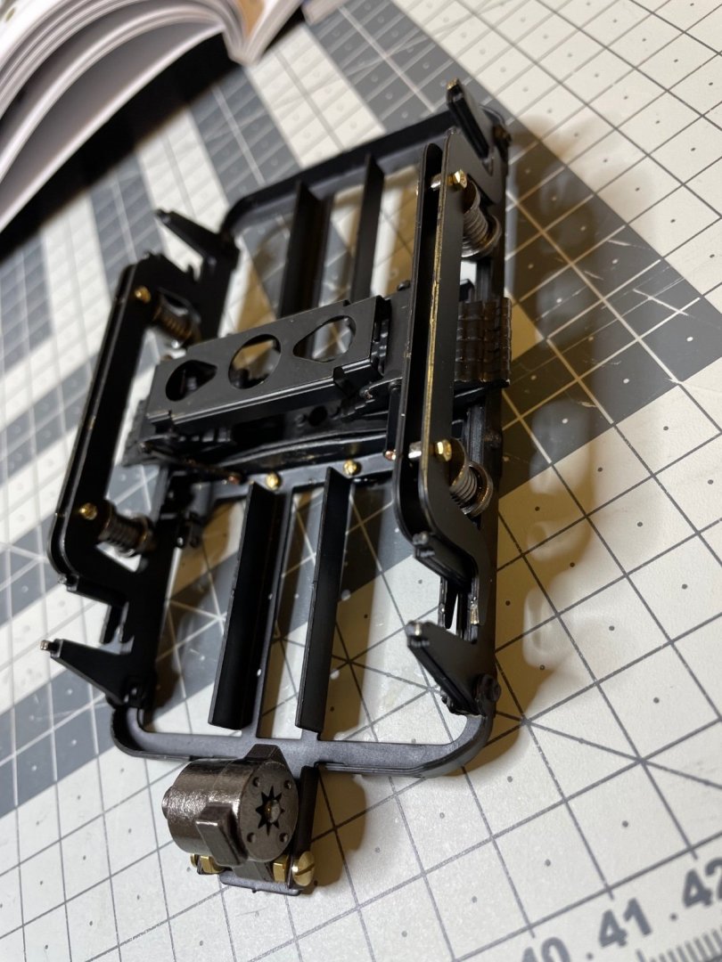
Figure 109: Dynamo belt installed.

-
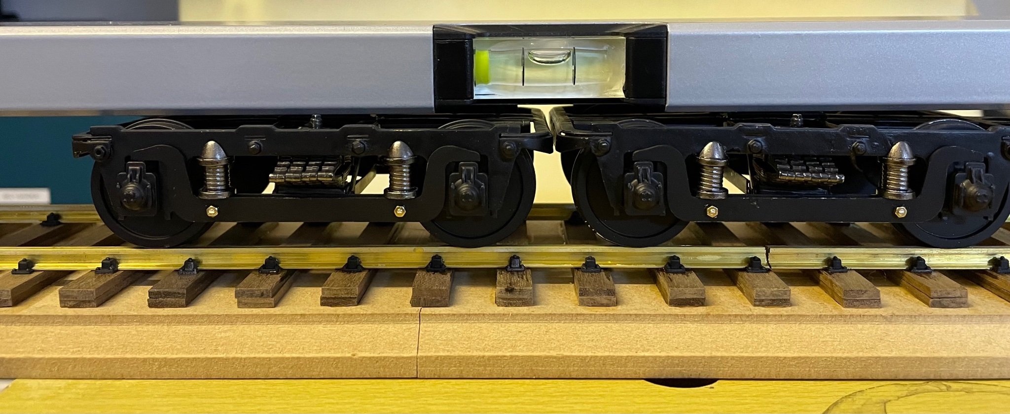
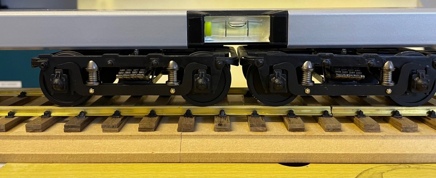
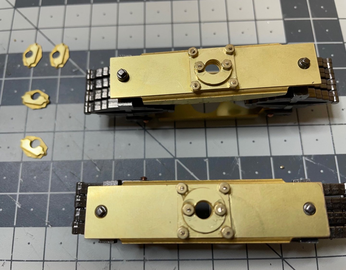
Figure 108: Testing the bogies together on the rail to ensure that they are aligned. If one is higher than the other, then there is a risk you'll fall from your bed in the night due to inclination 🤣. So far looks fine and I can glue the bearing blocks holding the rods in place.
- 293 replies
-
- 10
-
-
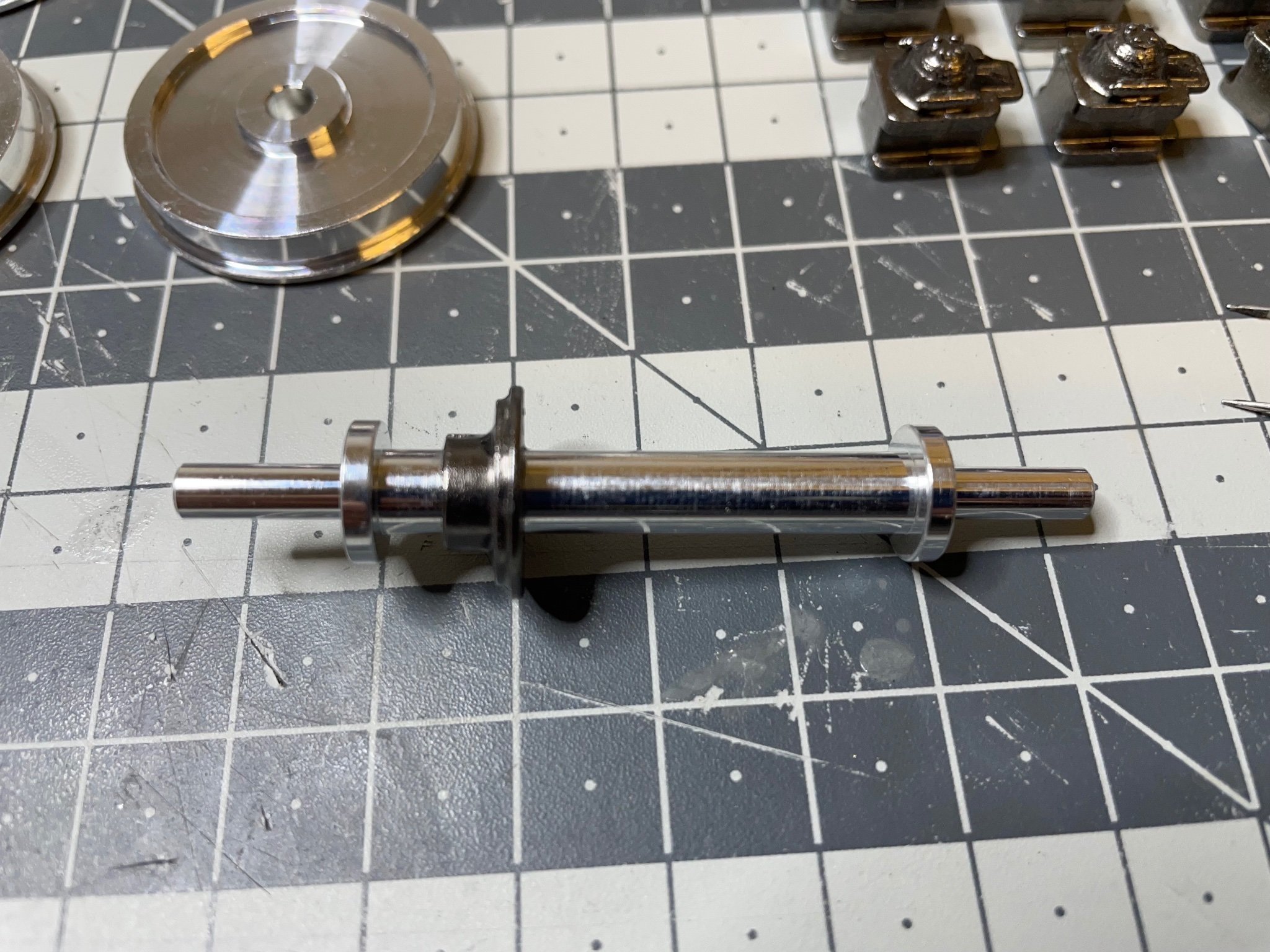
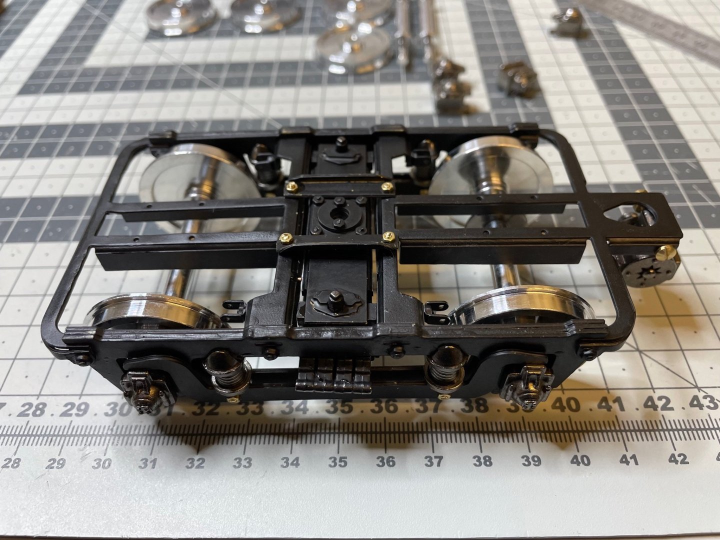
Figure 107: Wheels dry fit. The wheels are not supposed to be glued. They should rotate freely and independently. The rod will stay still. This is needed especially for the rod above, which is connected to the dynamo via a brass belt. I see some build videos in Youtube gluing everything to the wheels including the brake shoes (to come later in this log). Such approach is only for in case you are absolutely sure you are building a fully static version, in which the wheels will not move!
-
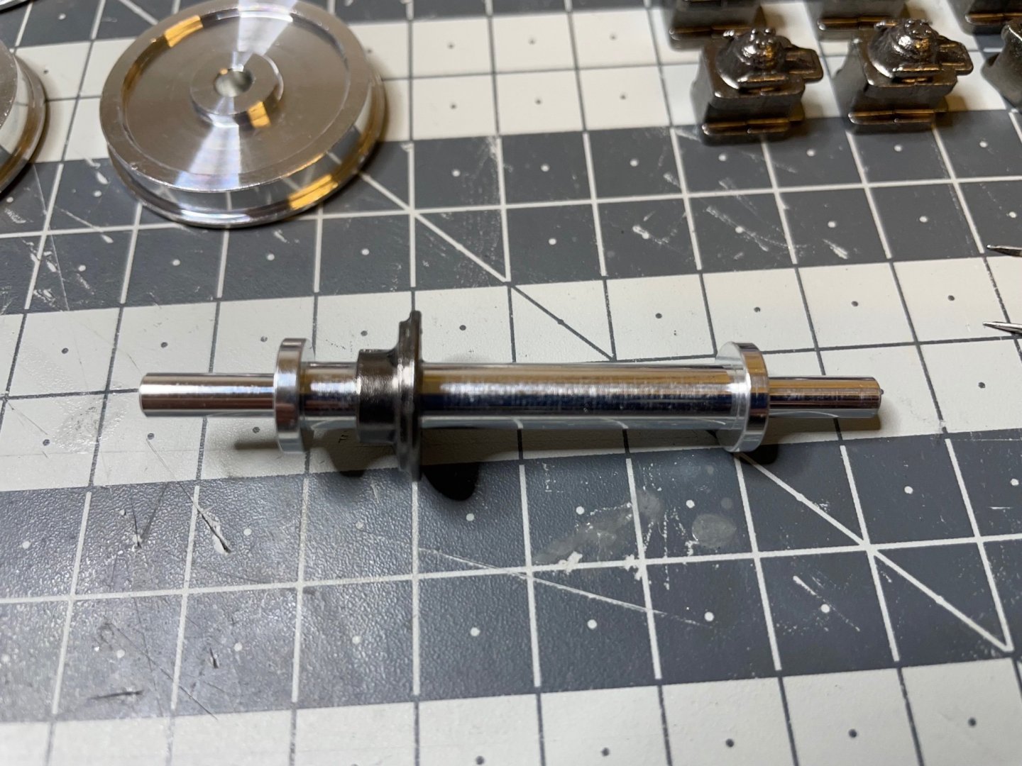
Figure 106: This wheel set differs from the other three by the additional wheel on the rod. It is for the belt turning the dynamo.
-
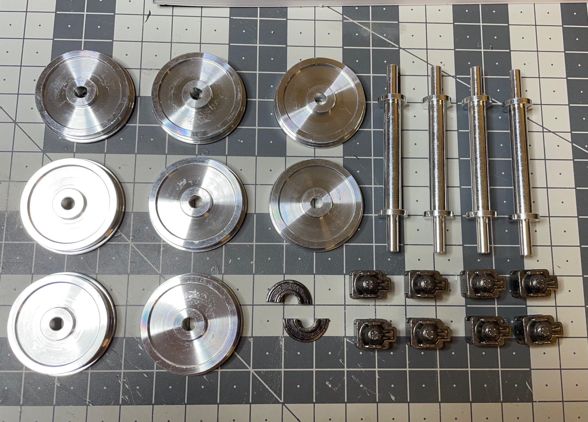
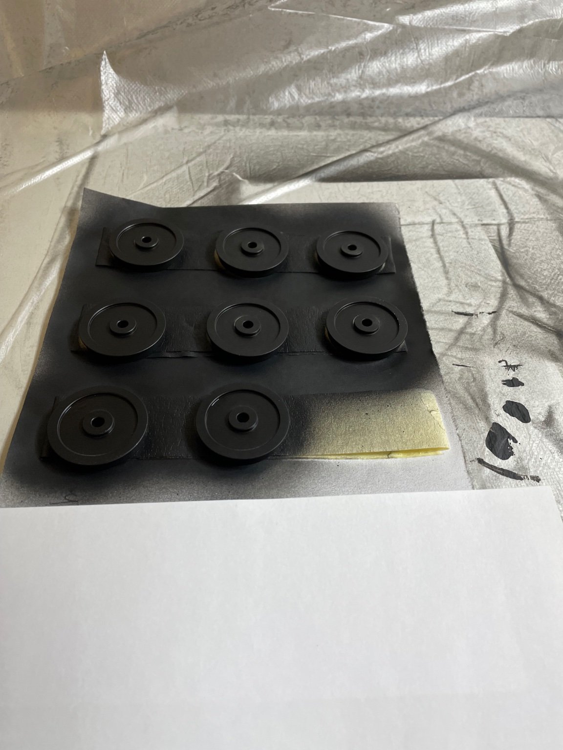
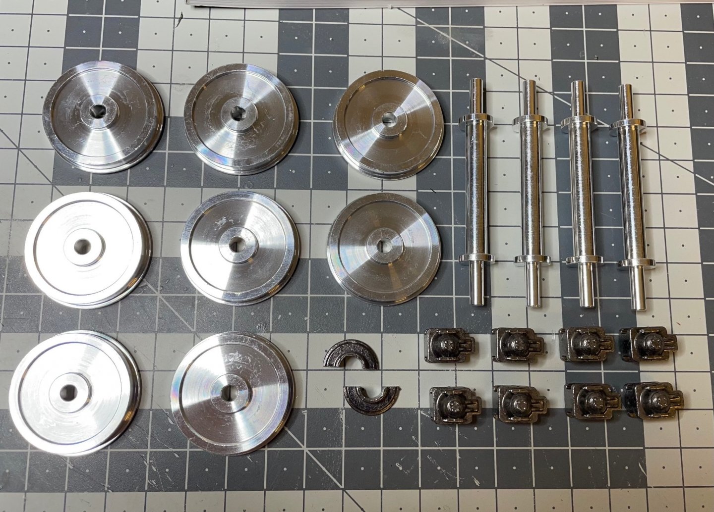
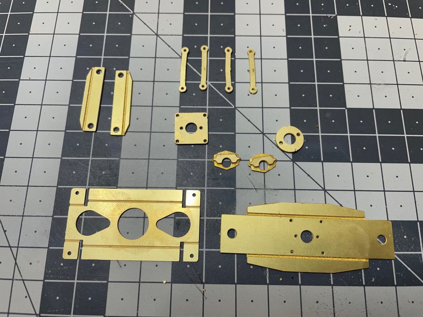
Time to install the wheels. Figure 103: Parts. Figures 104-105: Painted matt black with airbrush.

- 293 replies
-
- 10
-
-
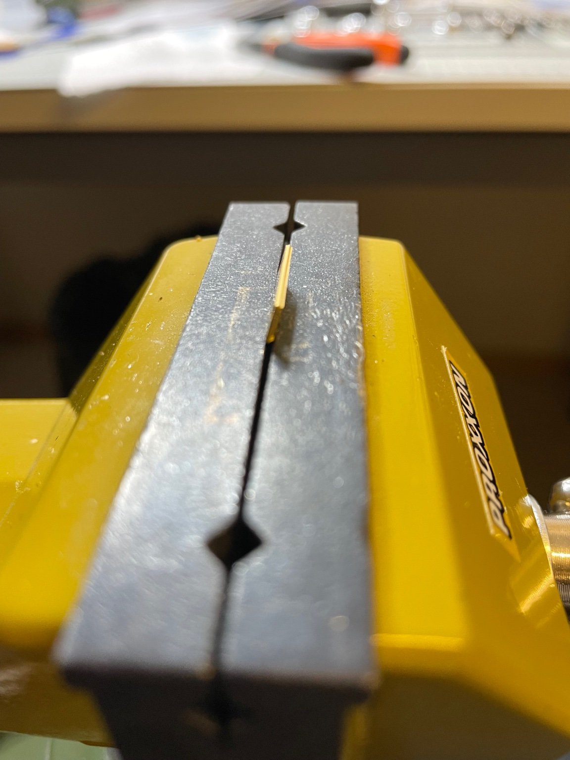
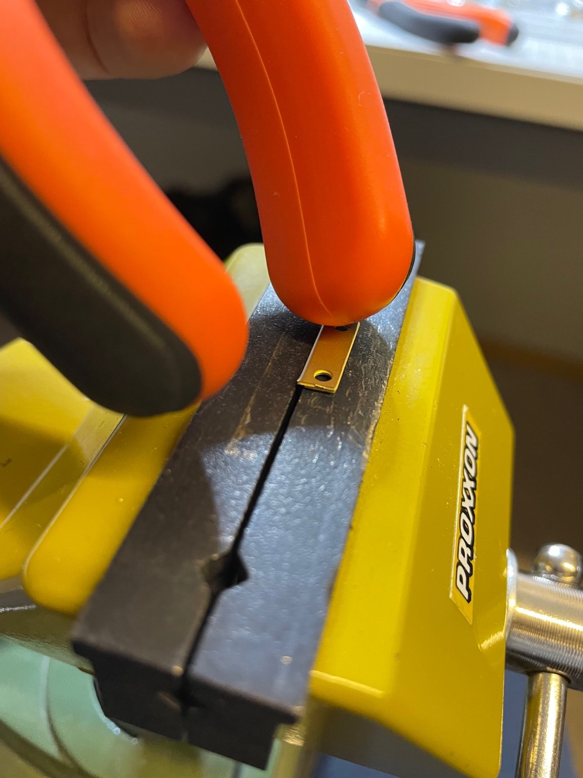
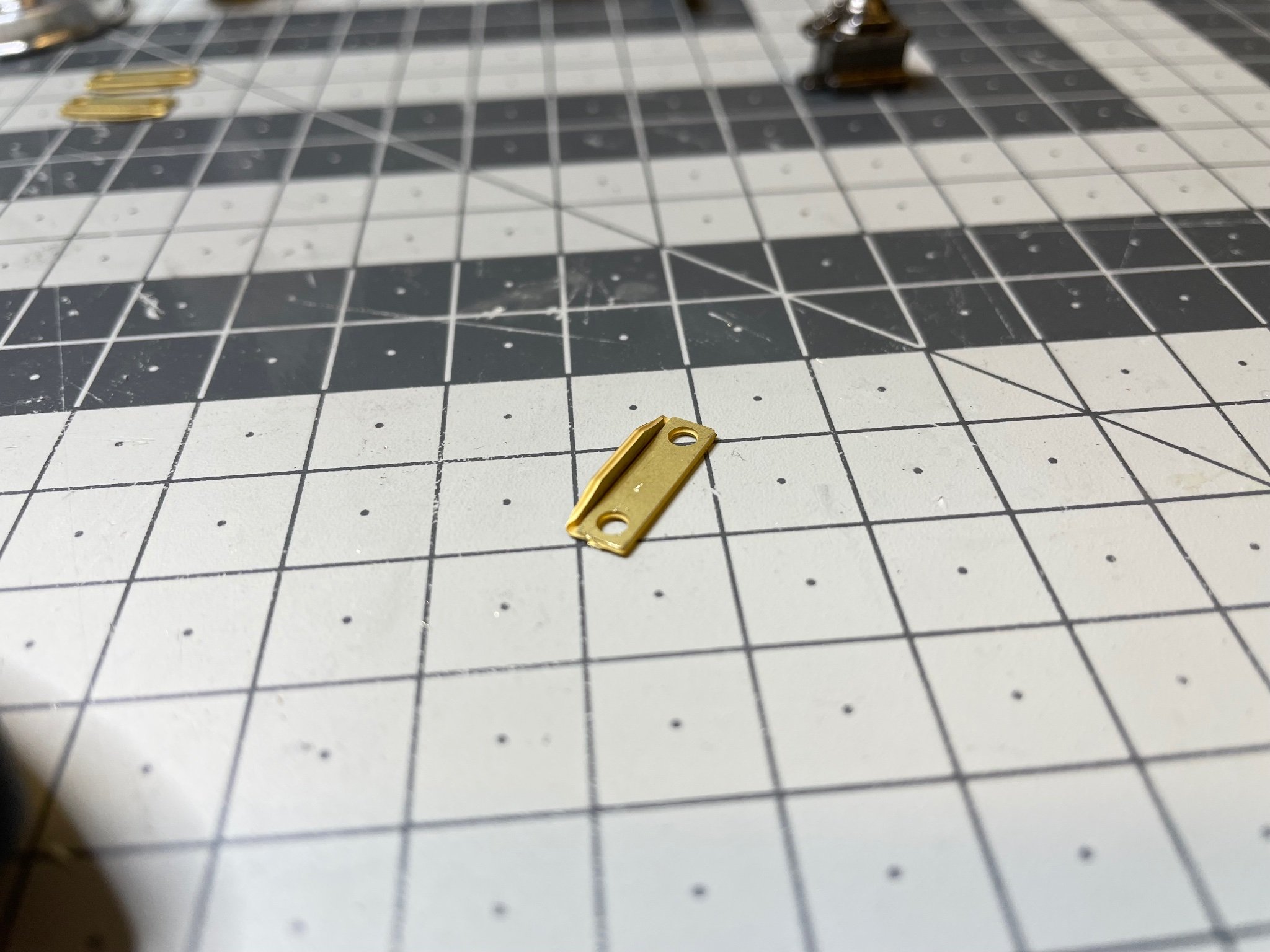
BUILD DAY 7: 2,5 hrs (TOTAL: 23 hrs) Figures 99-102: This is how I bend this kind of small and thick brass parts. I used plier's handle as a hammer. A soft rubber hammer would be a more proper tool for this purpose.


-
Amati has replied to my request, they are sending the missing part. Fingers crossed 🙂.
-
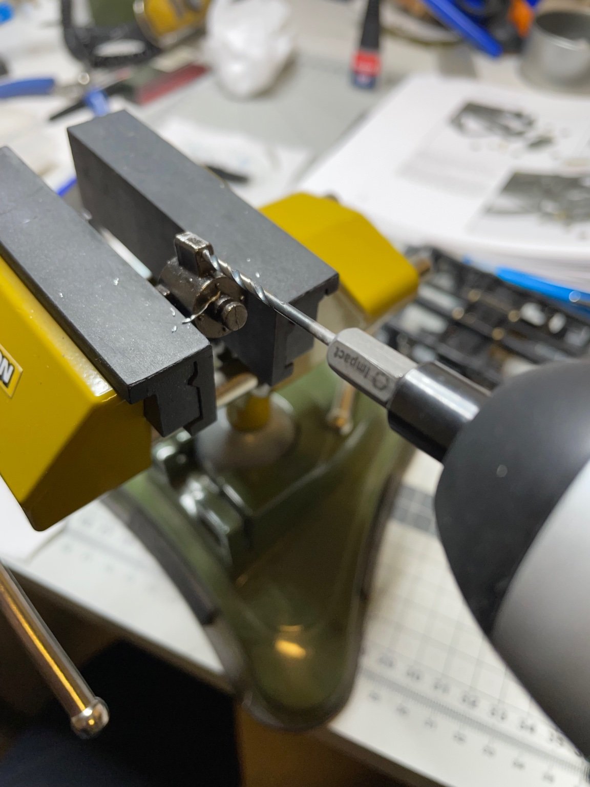
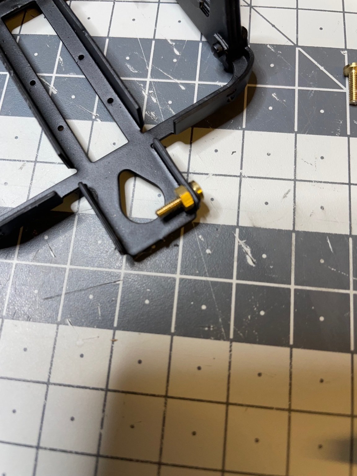
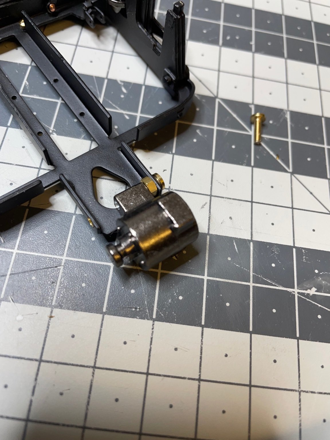
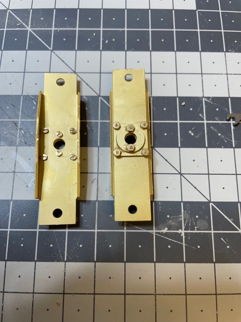
Installation of the dynamo. This part is only on one of the frames. Figure 91: Dynamo is installed using 2 bolts and nuts, which need to be shortened to size (10mm and 7,5mm) and must fit in the dynamo. Well, except once again they don't. Hence, drill. 🤣 Figures 92-98: Showing the process of dynamo installation. That's all for today! Thanks for watching!


- 293 replies
-
- 14
-
-
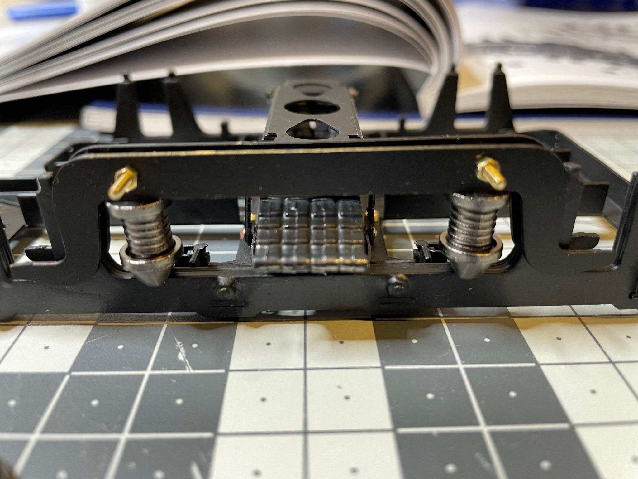
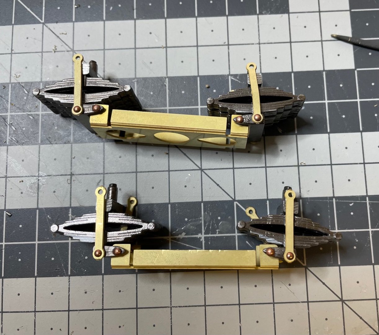
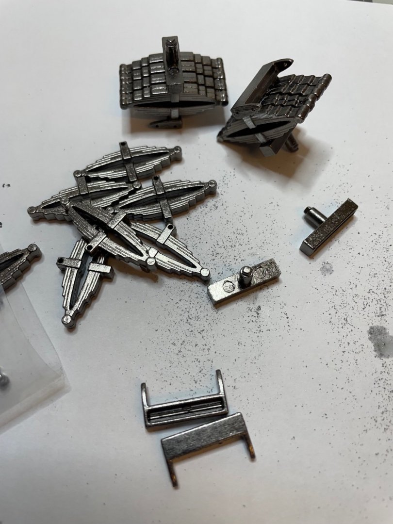
Figure 87: The so called "struts" and springs. This will be the structure where the wheels will sit on, later. Figure 88: Painted in matt black as usual The springs consist of 3 parts to be glued together. But I choose a bit different order than in the instructions, to ensure accurate alignment: - First I glued the two parts which will be on the side of the struts (like in Figure 89 below), - Then screwed them to the struts - Inserted the 3rd part of the spring structure to the frame - Finally placed the struts on top od that 3rd part. Figure 89: Figure 90: Now everything looks perfectly aligned.


- 293 replies
-
- 12
-
-

-
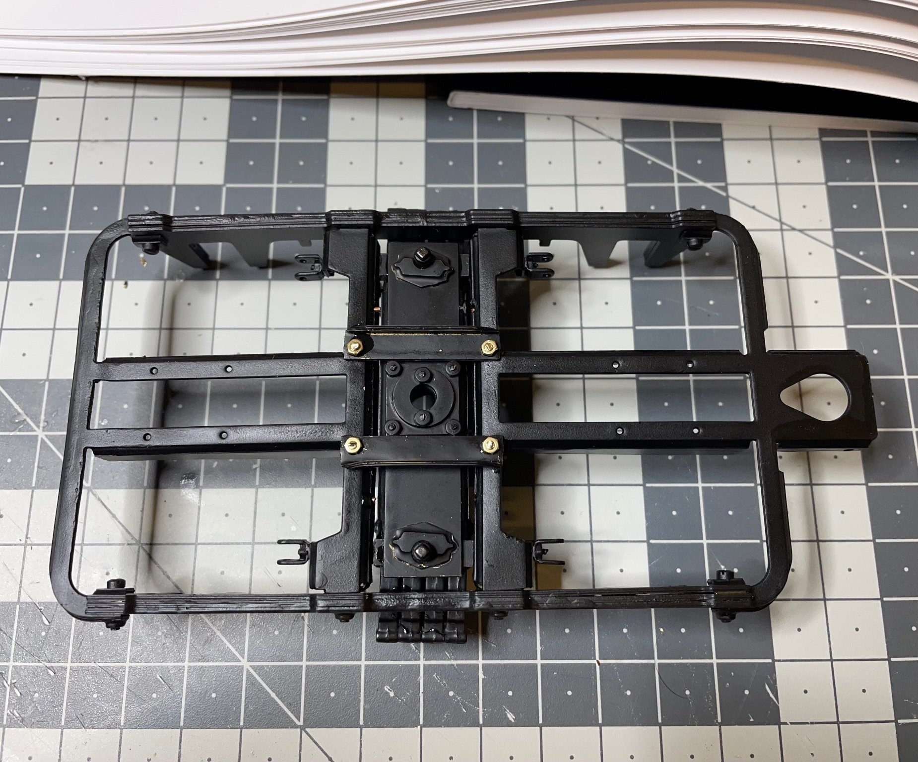
Figure 85: Suspension structure painted and mounted in place. Figure 86: How to mount the suspension structure to the frame. See the brass rods connecting on left and right side. Altogether four of them. They also use copper rivets to allow the suspension to move.


- 293 replies
-
- 10
-
-
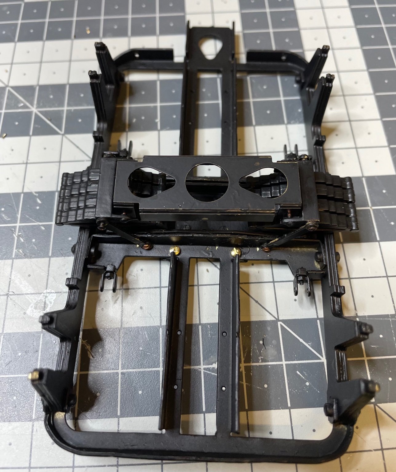
Figure 84: The moving structure is ready. The parts are mounted using copper rivets, not bolts, to allow them rotate freely.
- 293 replies
-
- 12
-
-
More photos on the assembly process. Figure 82: Dry fit on the springs, for aligning the small parts on the left side of the picture, to be glued on either side of the brass component. Figure 83: More drilling. The holes are simply too small. They are almost there only for a reference of the correct location :).
-
Figure 79: Brass parts for the suspension. Figure 80: Bent as instructed. Figure 81: Parts mounted and fixed using 1,5mm bolts.

-
BUILD DAY 6: 3 hrs (TOTAL: 20,5 hrs) Continuing with bogies. Now the frames are ready, it is time to fill them. Note: The manual is instructing to finish one of the bogies first and then repeat the almost identical steps to build the second one. I will not follow this approach fully, nor a parallel building progress. Instead I decided to go with a "hybrid" approach. I build some pair of components at the same time where it looks more convenient and keep them aside until I build the second bogie. Next on the line is the suspension structure. There will be two of these. Figure 77: Die cast parts. Figure 78: You will need to enlarge almost every hole by drilling, in order to fit the bolts conveniently. Do not try to push/pull the bolts with pliers or other tools to pass them through the holes, their pitches will get ruined very easily and the bolt will be impossible to use. Better open a wider hole and just insert the bolt smoothly.

-
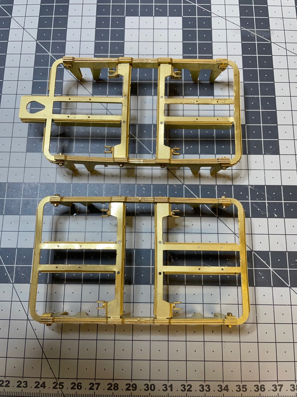
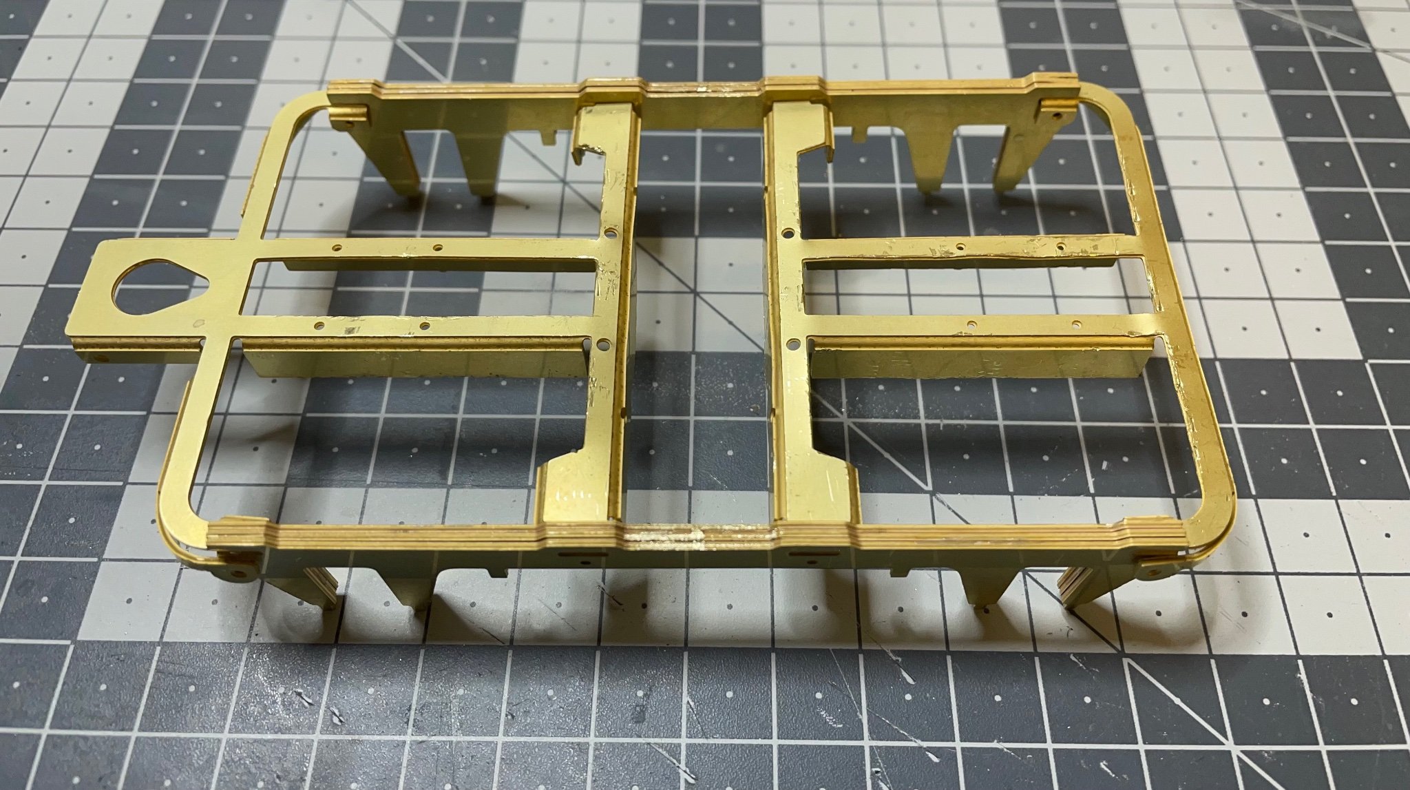
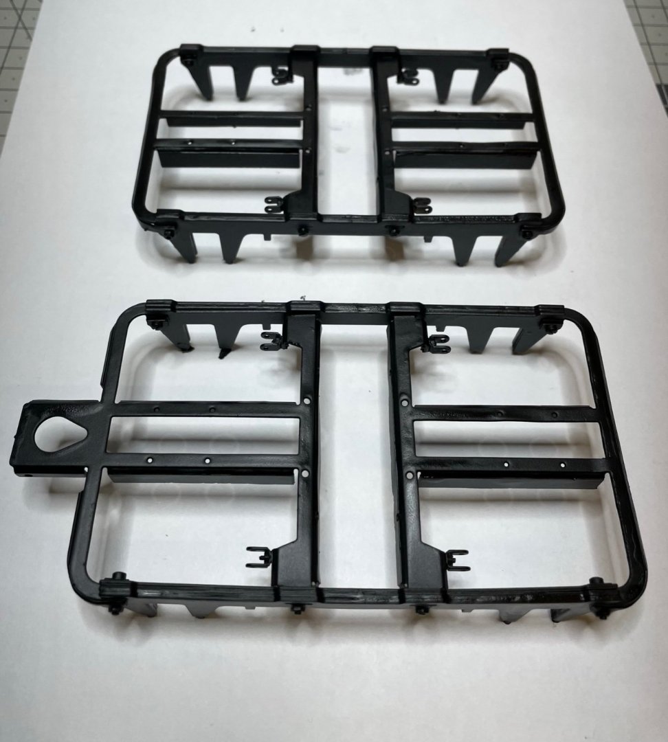
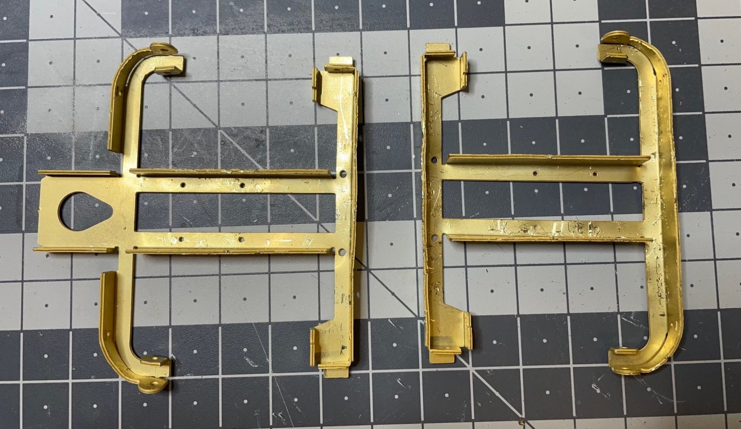
Figure 76: Bogies' frames painted. - 1 layer matt black spray primer - 1 layer matt black spray paint.
- 293 replies
-
- 12
-
-
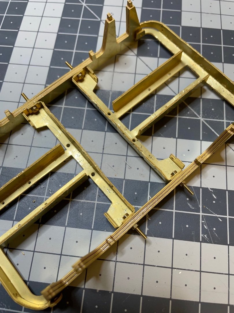
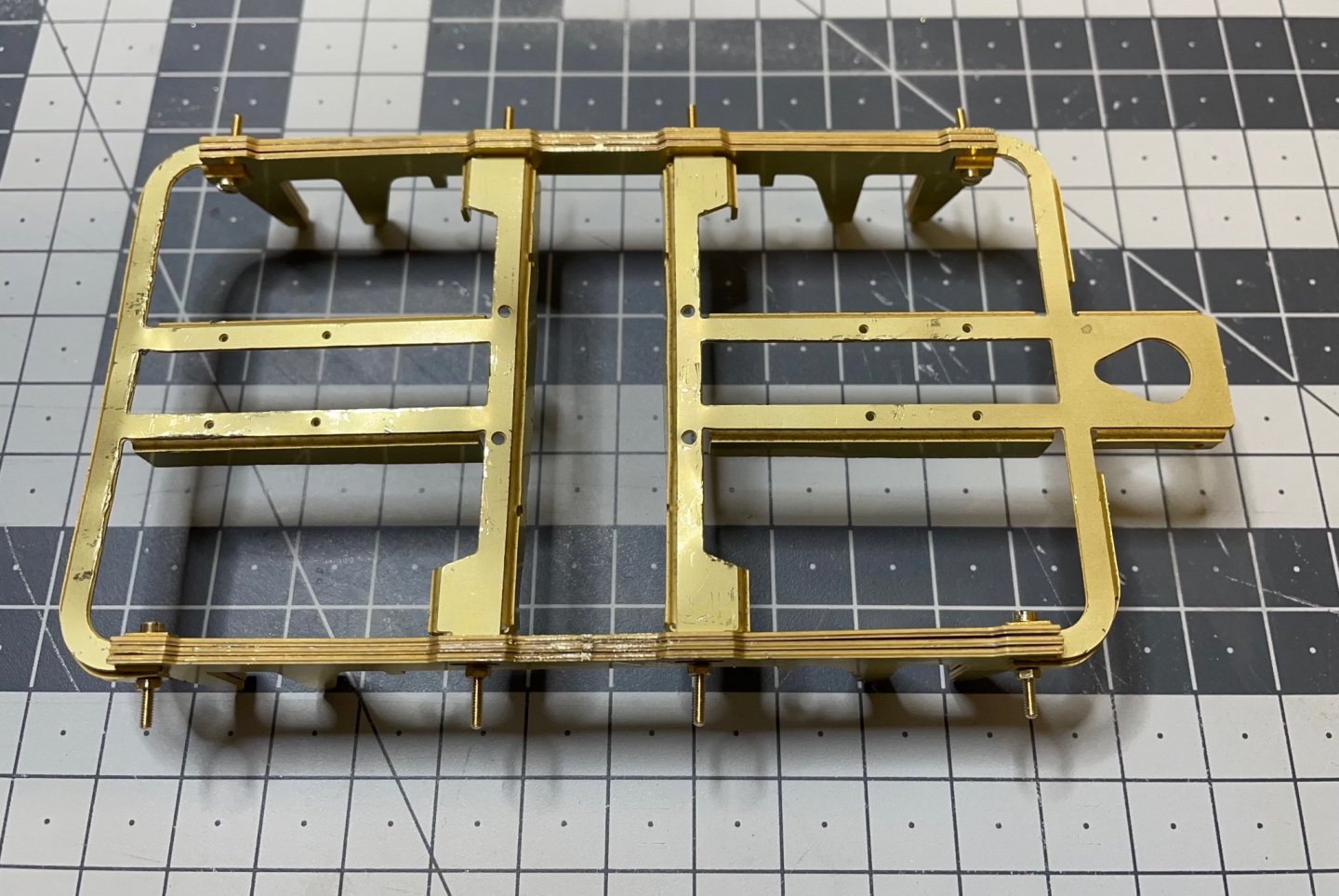
Figure 75: Followed the similar procedure for the other bogie. Now there are two of them. Bogies are ready for first painting. There are still a lot to be done on them, but as per the instructions now they are at a stage ready for painting. That's all for today! Thanks for watching!

- 293 replies
-
- 13
-
-
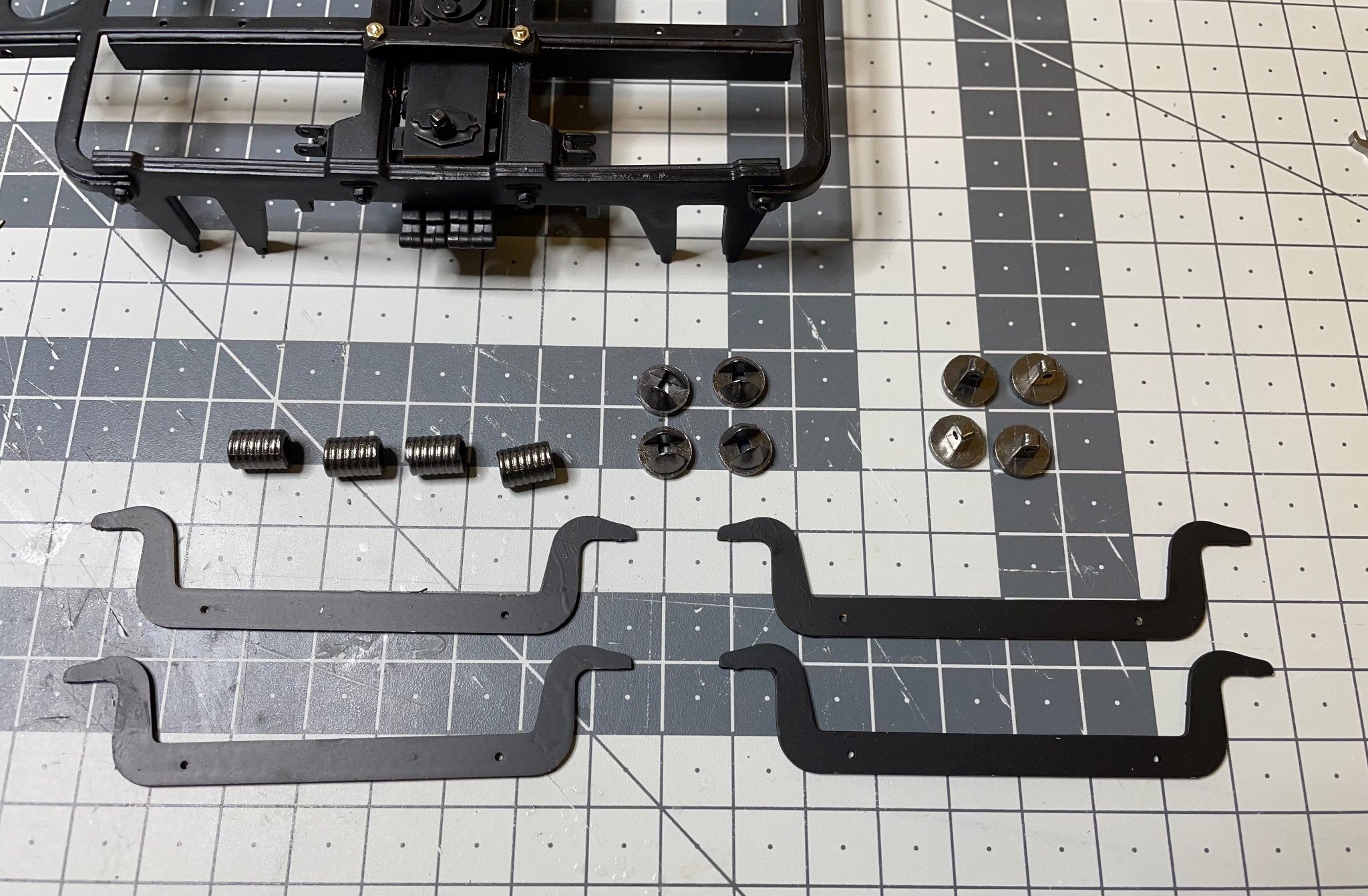
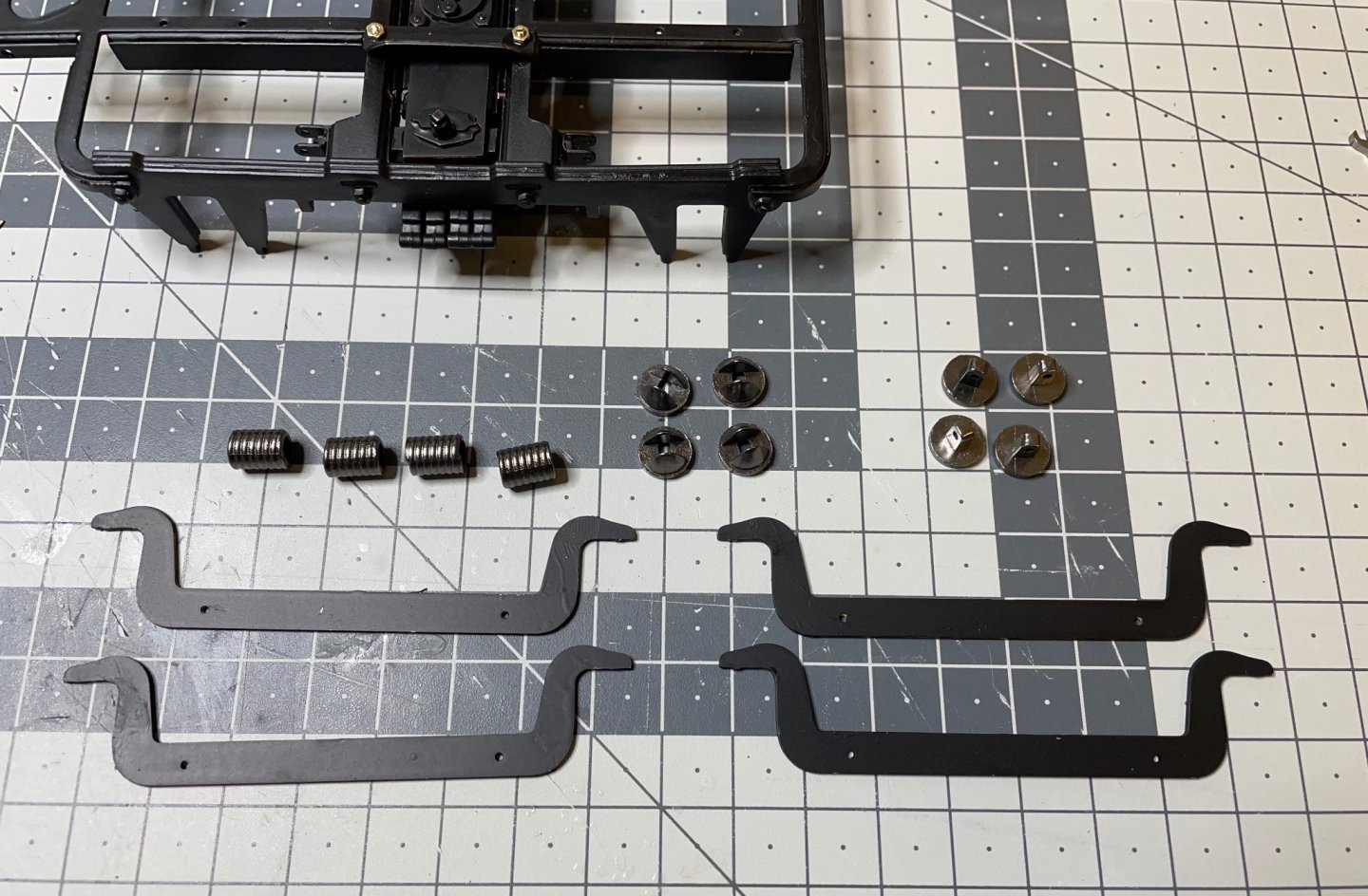
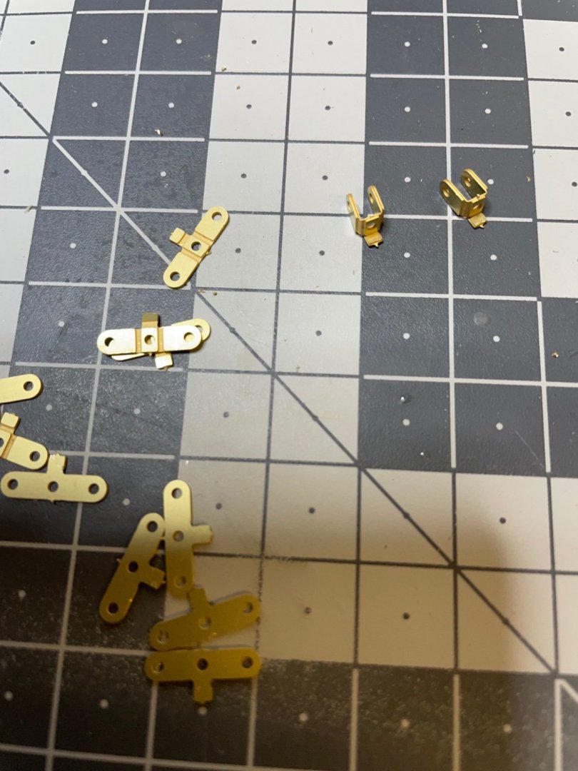
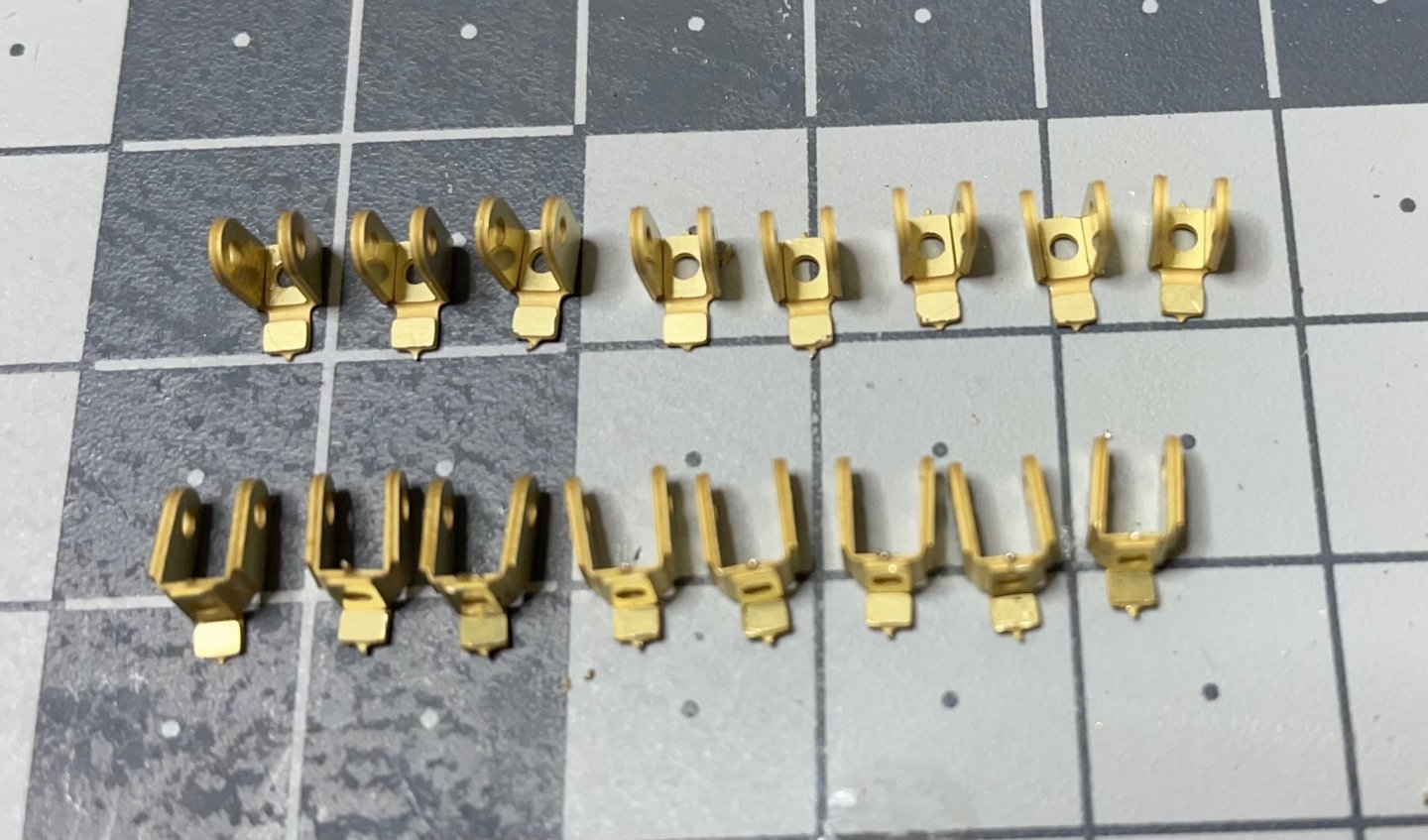
Figure 69: Brackets, on the brass sheet. Figure 70: Removed 16 of them from the sheet. 8 of them are to be bent different than the other 8. Some will be used at a later stage. Figure 72: Bent the parts as instructed. Figure 73: The brackets are in place.


- 293 replies
-
- 13
-
-
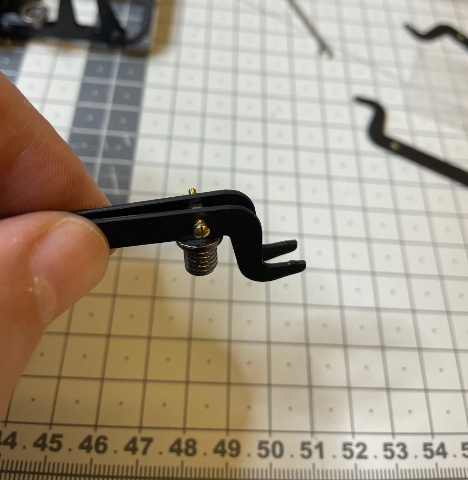
Figure 63, 64: Legs, formed of 3 pieces glued with super glue. 2 identical parts and on different. Pay attention to glue correctly. Figure 65: Legs in place. Dry fit. Figure 66: My best friend of the day. A 2,5mm miniature hex wrench. Without it, I don't know what I 'd do. Figure 67, 68: First set of fixing screws in place. They will be trimmed later.


- 293 replies
-
- 11
-
-
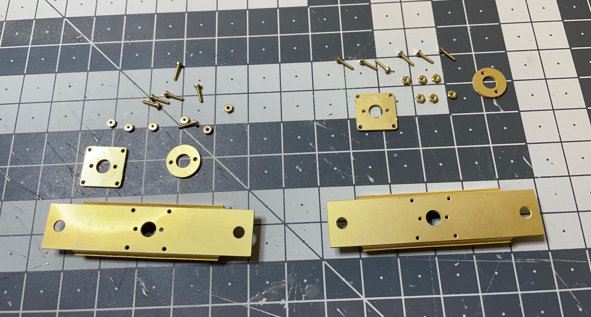
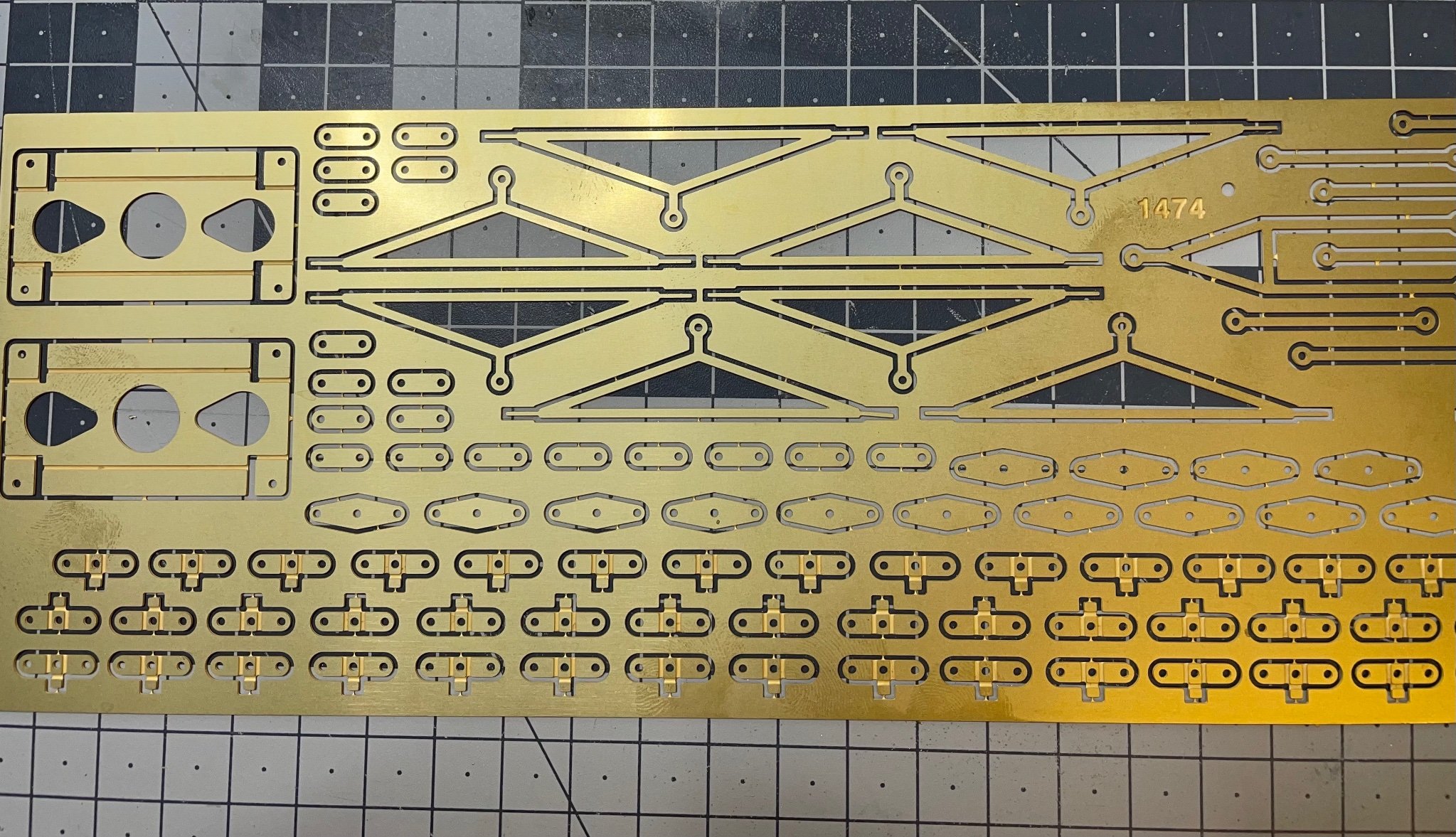
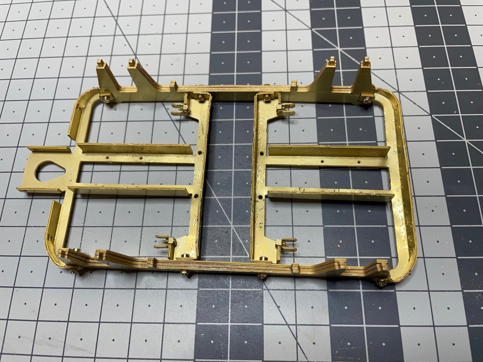
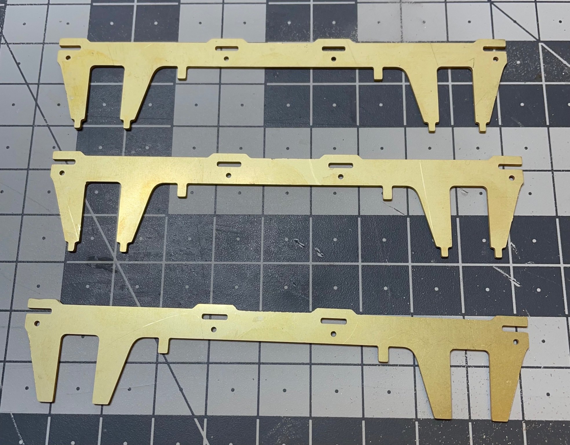
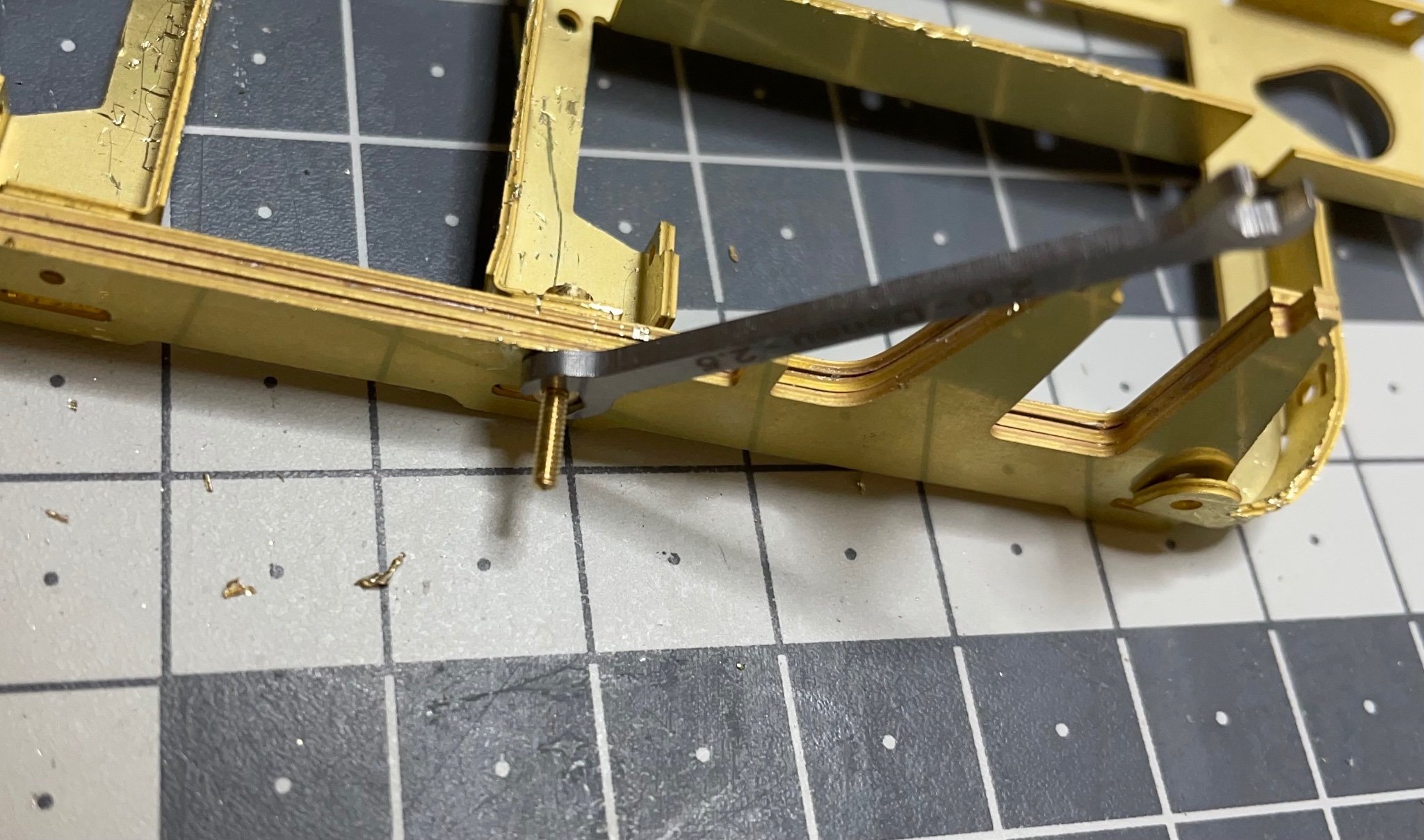
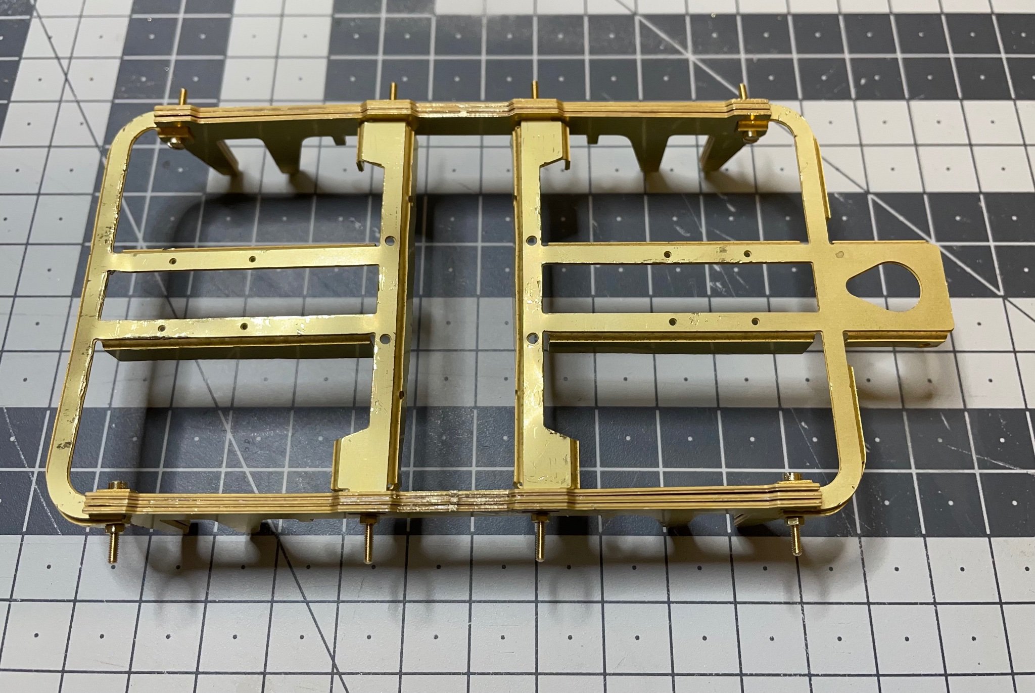
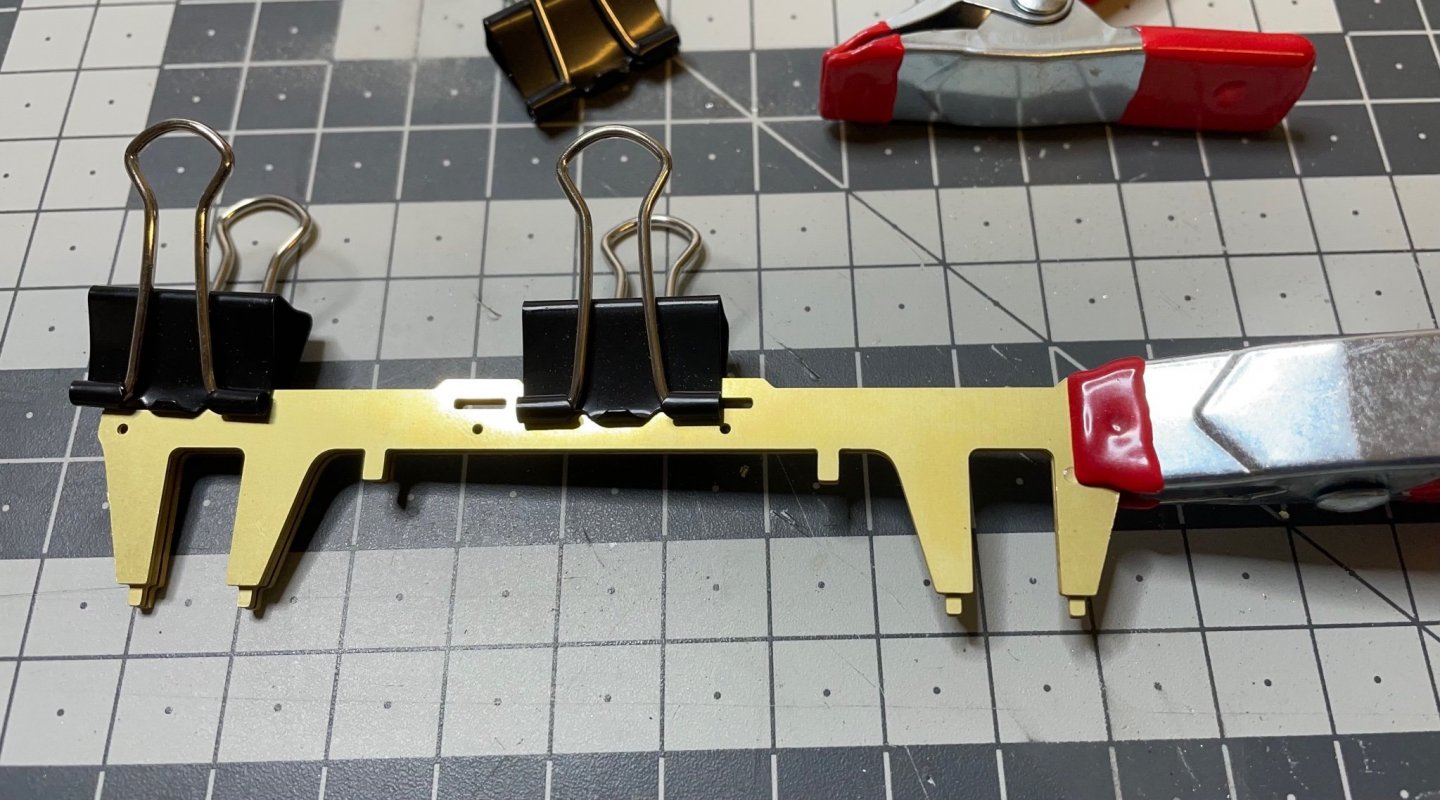
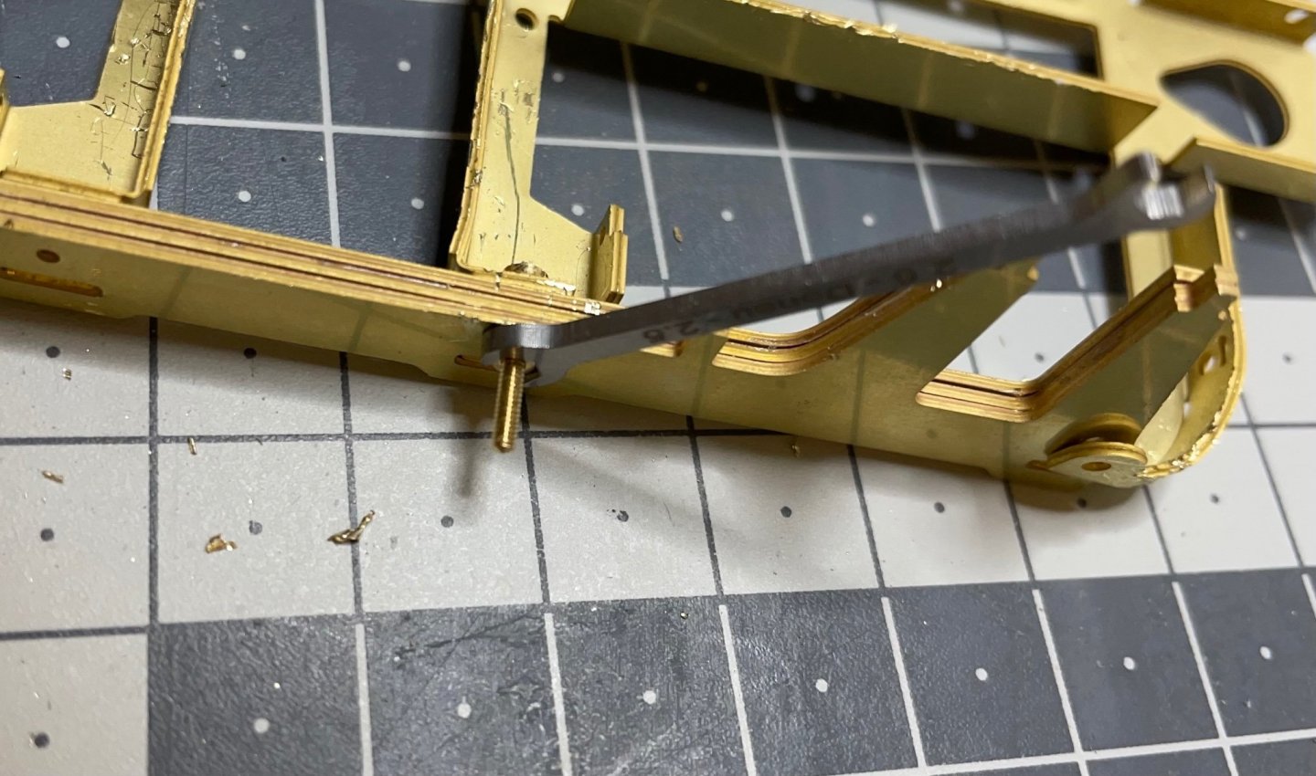
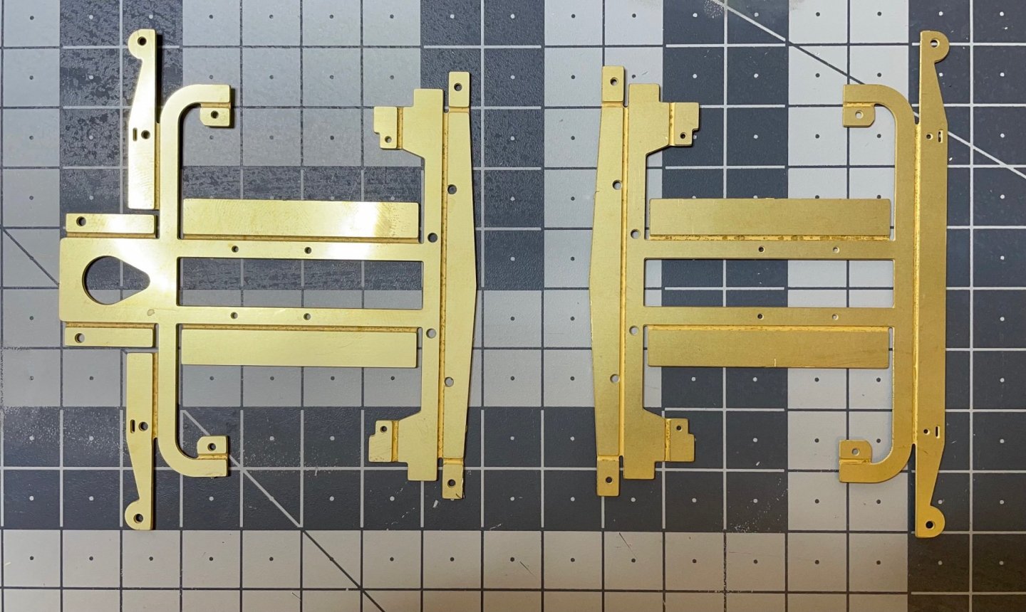
BUILD DAY 5: 6,5 hrs (TOTAL: 17,5 hrs) Today I started to build the bogies. This was a 6,5 hours of blood, sweat and tears. The components come in quite thick brass sheet. I have to say that the build videos of this kit I saw on the internet about bending these parts, are like a joke. At least at my level of experience, there is no way bending them easily using just a pair of pliers and hand. I am talking about bending the long sections on the sides and "wings" in the center. Since the section you want to keep flat is much narrower than the section you want to bend, the flat part bends before the section which you actually want to bend. Then a lot of twisting, unbending, hammering... I used double pliers, hammer, thin pliers, briefly everything at hand while trying not to damage the visible side. Well, after all, I am quite happy with the result, for a first time handler of brass sheet at this scale. Figure 62: This is how we start. Figure 63: The hardest areas are bent. Never mind the small distortions. I will straighten them on the way as good as I can. Most scratches will stay under the paint and on the invisible side once they have been installed under the chassis.
- 293 replies
-
- 10
-
-
By the way 1 week and no response from Amati about the missing L-profile part. I sent them another reminder email.
-
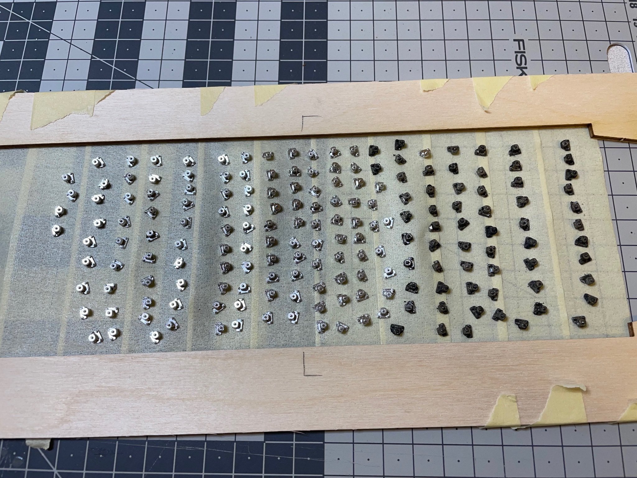
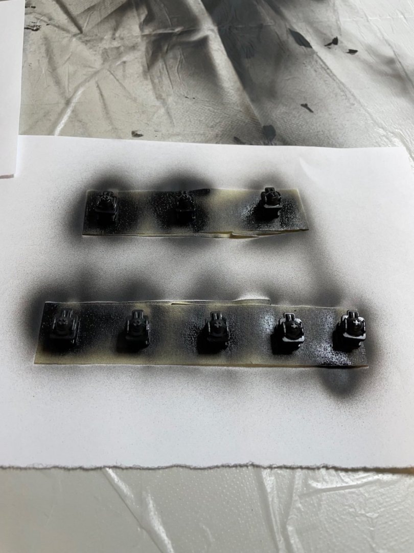
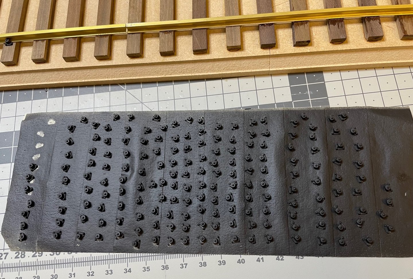
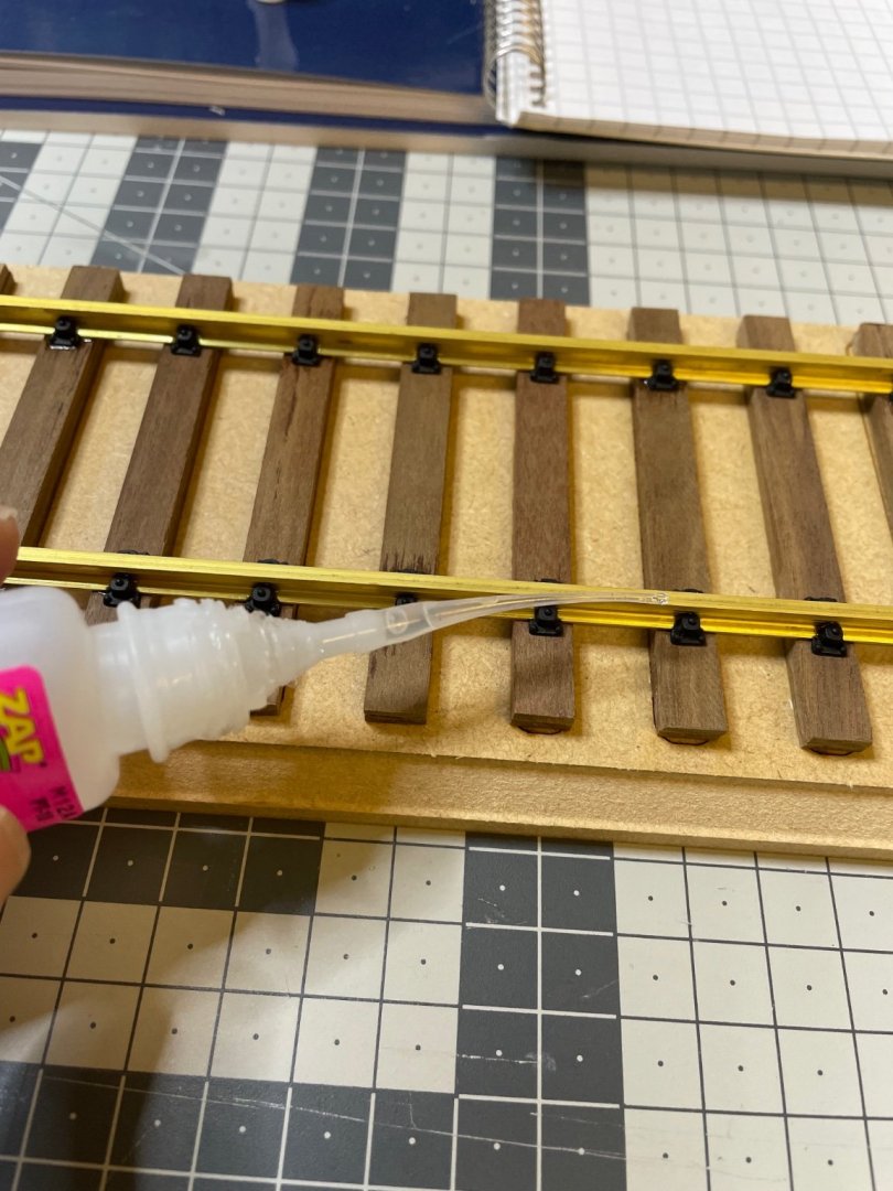
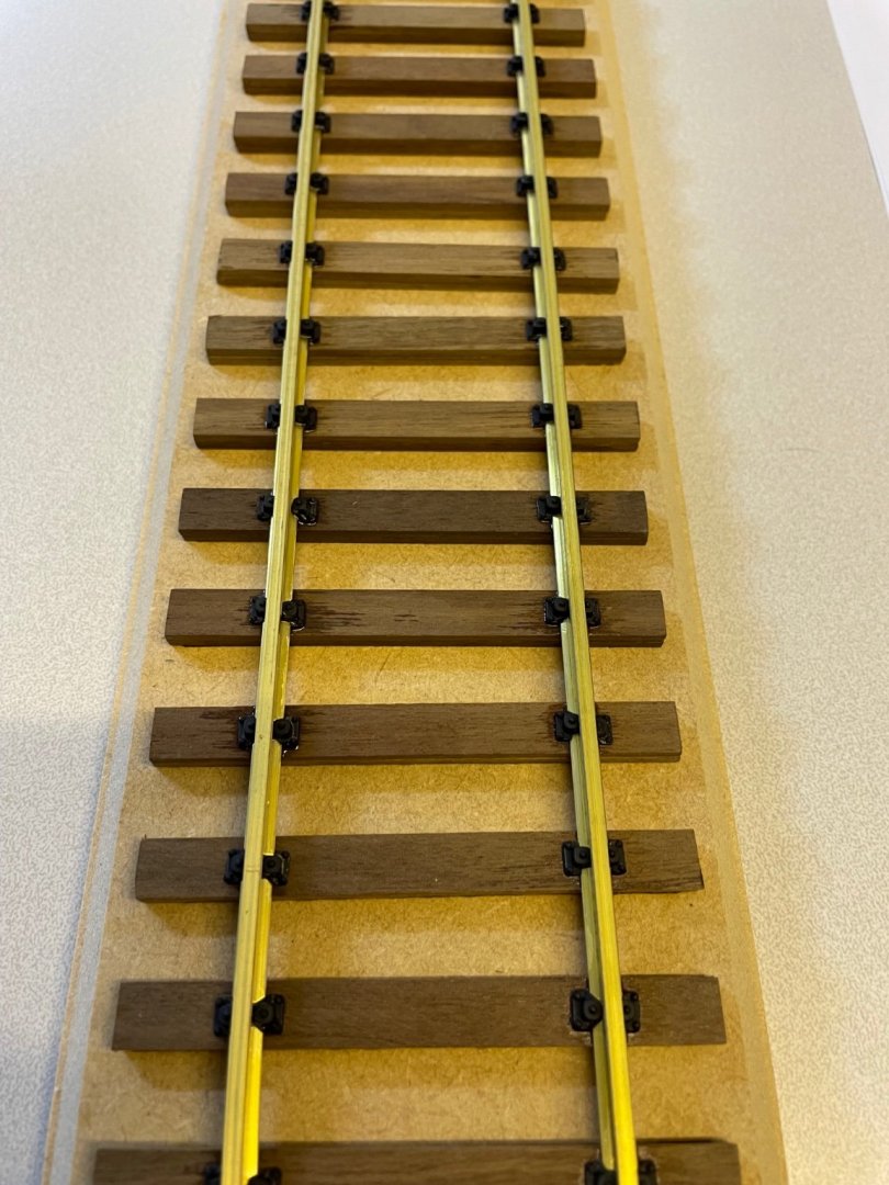
BUILD DAY 4: 2 hrs (TOTAL: 11 hrs) Completed the railway as described in the manual. Like I wrote above, I don't know what to do with it yet. If I choose to include it in the display then I may add some pebbles etc as decoration. So far I put it aside. Figure 58: Fixings for the rails placed on the sticky side of masking tape, invisible sides down, ready for spray paint. I tried staining some of them with the brass blackener but it didn't work well. That's why they look dark. Probably because these are pressure die-cast, not brass. There are 180 of them. Figure 59: Sprayed from a can of black primer. They look good enough and just the matt tone I wanted therefore I am not going to put any additional paint on top of them. Figure 60: I work in batches of around 10. I first place them dry on their spots, then apply a tiny amount of ultra-thin superglue with a thin nozzle from the rail side. It penetrates instantly between the part and the rail and bonds right away. Saves a lot of time compared to gluing and placing each piece one by one. Figure 61: Railway ready. That's all for today! Thanks for watching!

- 293 replies
-
- 11
-
-