


Ainars Apalais
-
Posts
74 -
Joined
-
Last visited
Content Type
Profiles
Forums
Gallery
Events
Posts posted by Ainars Apalais
-
-
Hi.
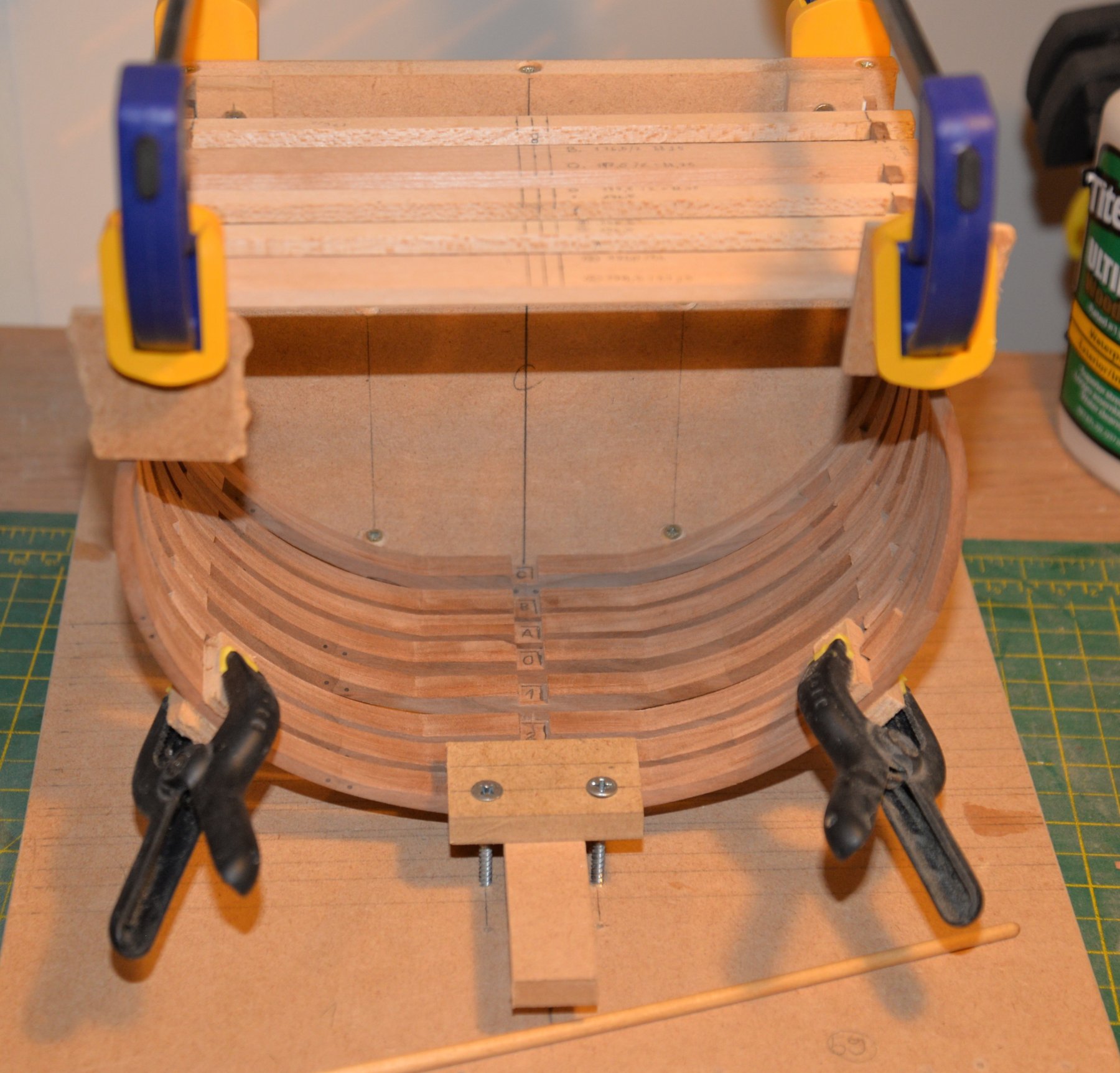
I add a little progress from my model.
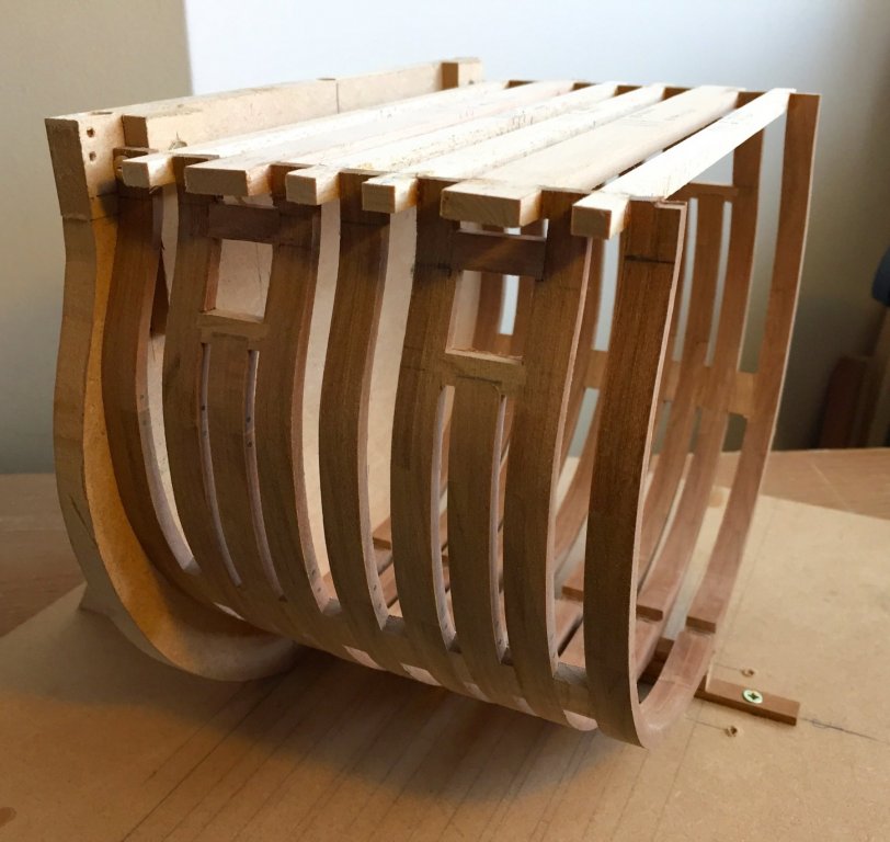
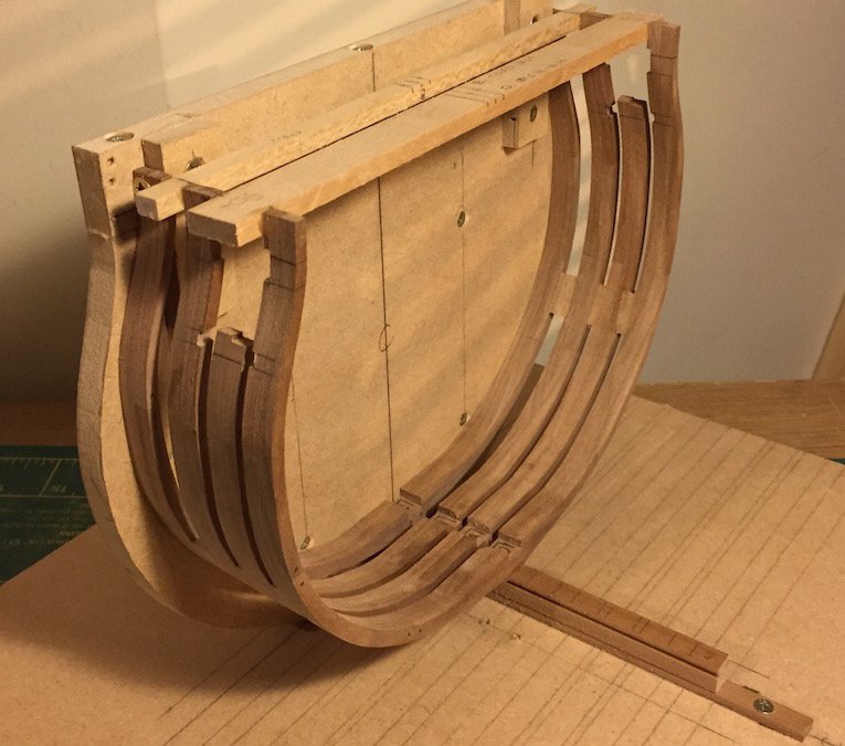
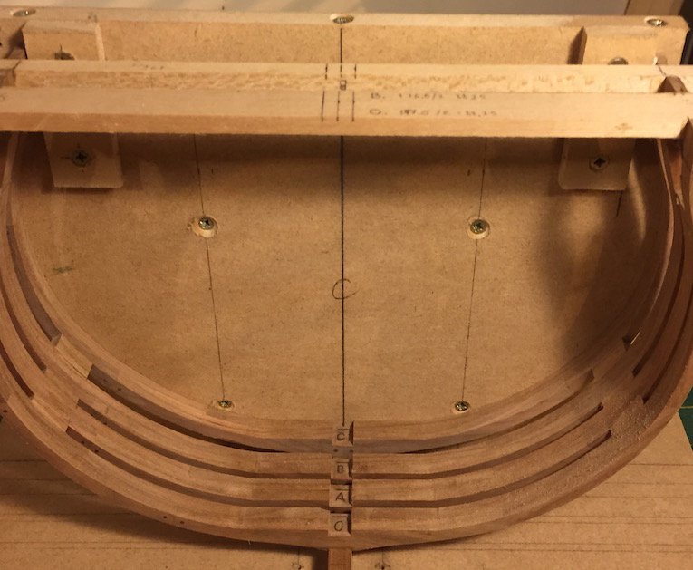
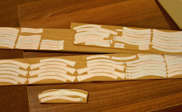
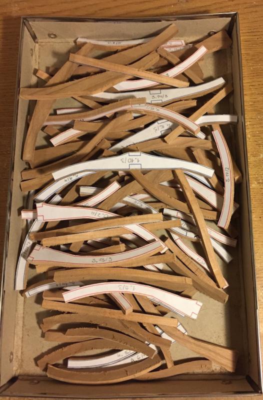
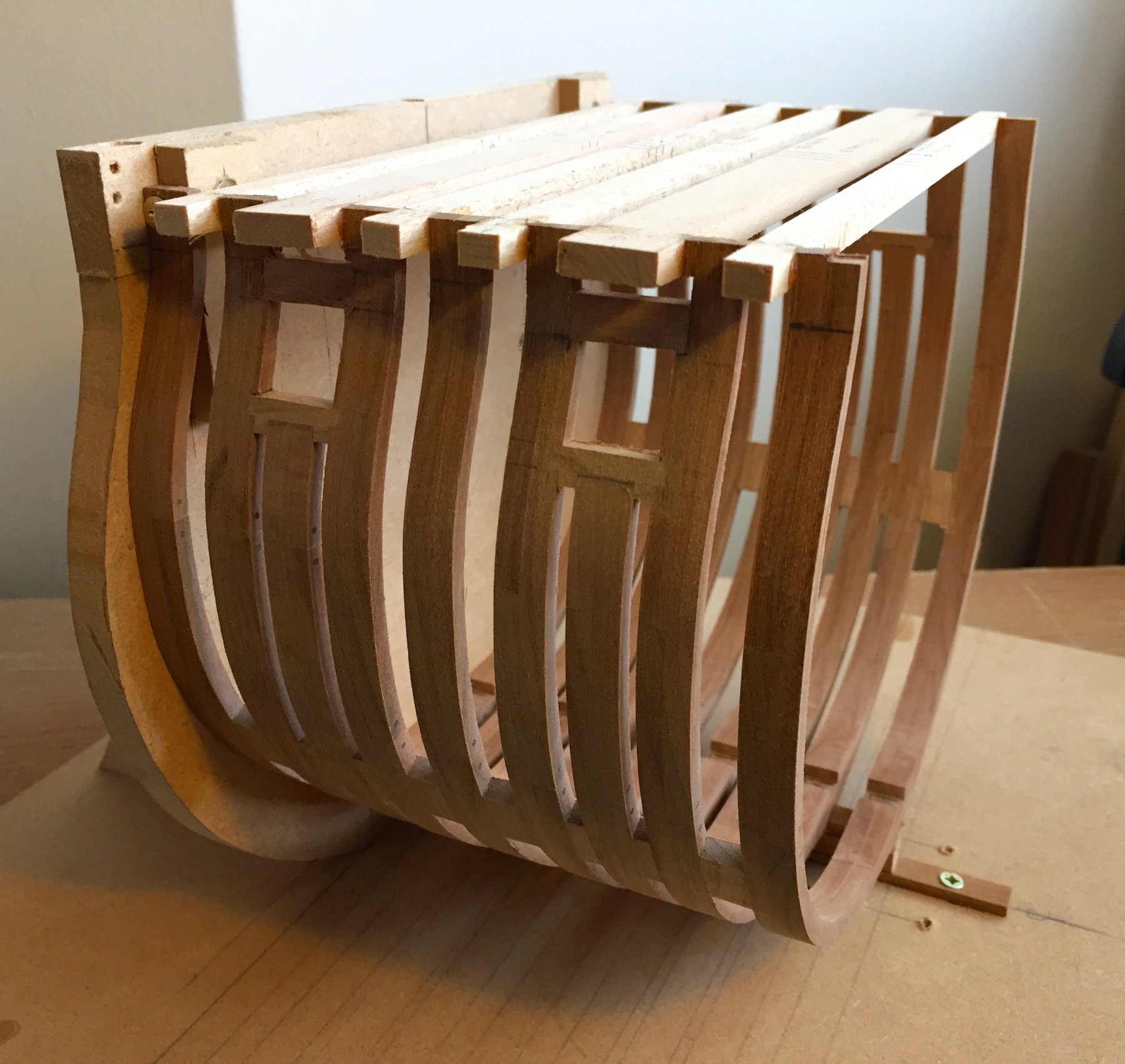
I glued the first top plank to hold together all frames. And cuts off all frames in the right-size.
And only then start sanding inside of hull.
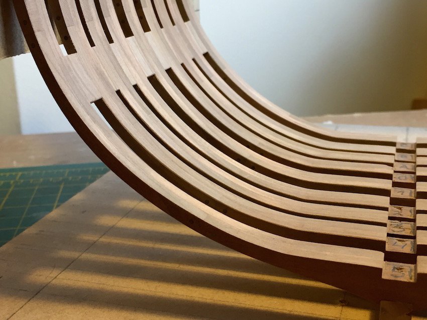
Step by step I stars planking.
First planks I made a slightly curved. To keep straight part in bottom of inside hull. As well pre drill holes in keelson for hold pillar.
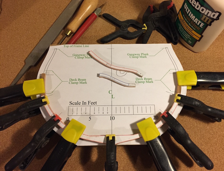
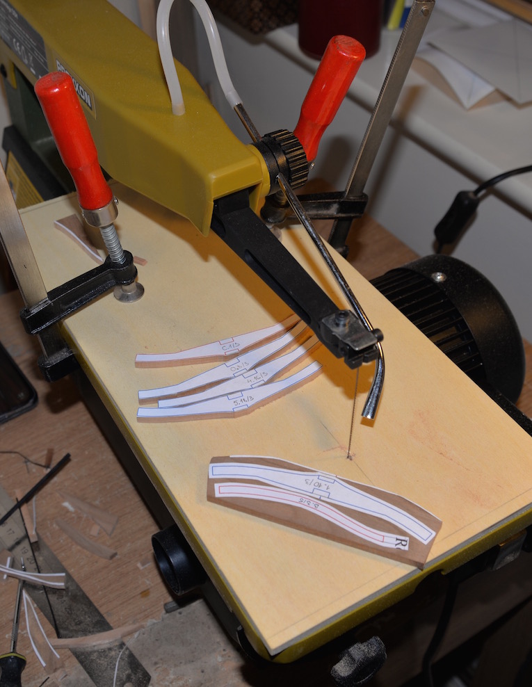
Next I made a couple of clams for planking. To make future work easier.
It works pretty well.
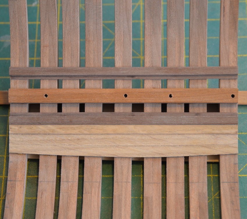
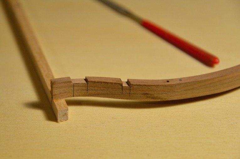
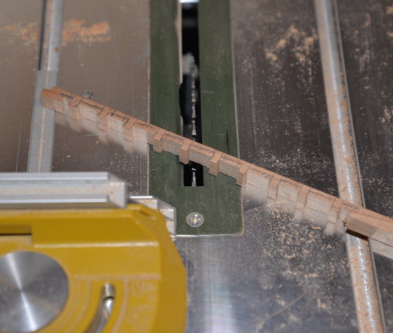
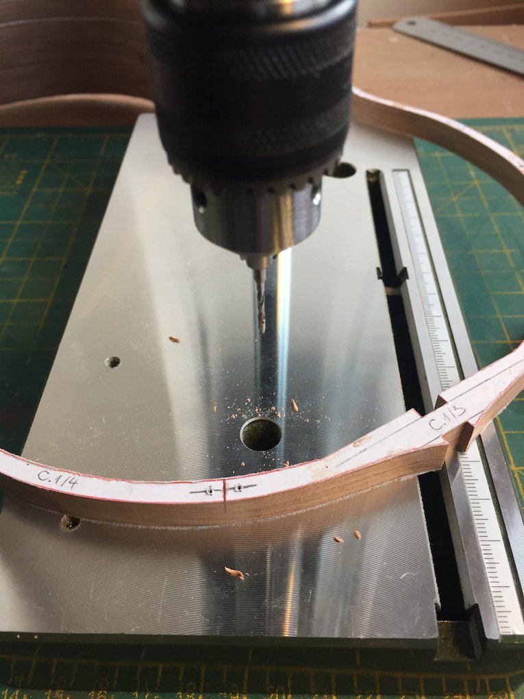
Cut out limber board in right shape. And cut it by small parts.
Then folded again all together and drill holes between.
By individual pieces I glued it In place. I leave only place for pump room.

It's all for the moment.
I hope so will have more free time to keep going.:)
Ainars
-
Hello all again.
Still I wanted to ask.
When I look at the other cross section models. There is also the added middle mast. As an example ChadB. For me it seems a great idea.
But where could I find more details?
Of the mast and the "walls" around him.
Part can be understood from the full-Build drawings.
But if it were possible that maybe someone can suggest something.
-
-
Thank you all.
Now I want to start hull planking.But just do not understand one thing.
So from the outside. Many model makers form joints between planks. I think if you look horizontally.Which in my opinion would be correct.
But it is with the inside? Here, I look at the other built models. All planks make a full-length.
Do not also be the joints?
Please someone suggest that it is more appropriate.
P.S. And once again I apologize for my English. I try as I can:)
-
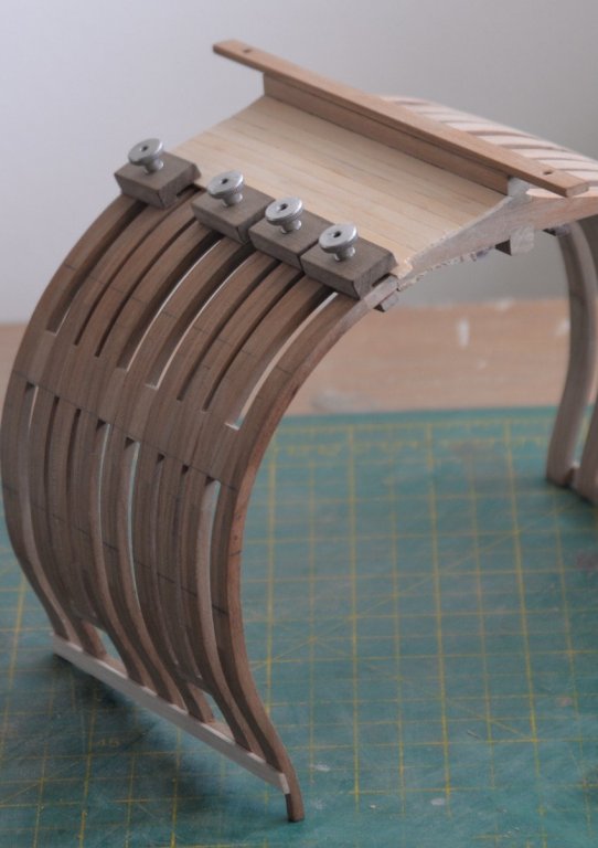
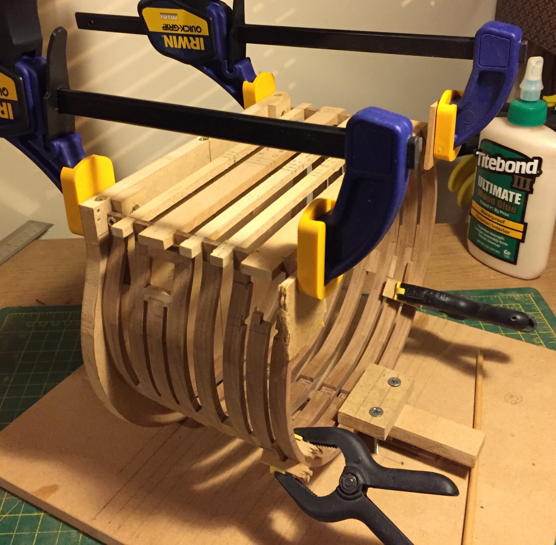
Hi.
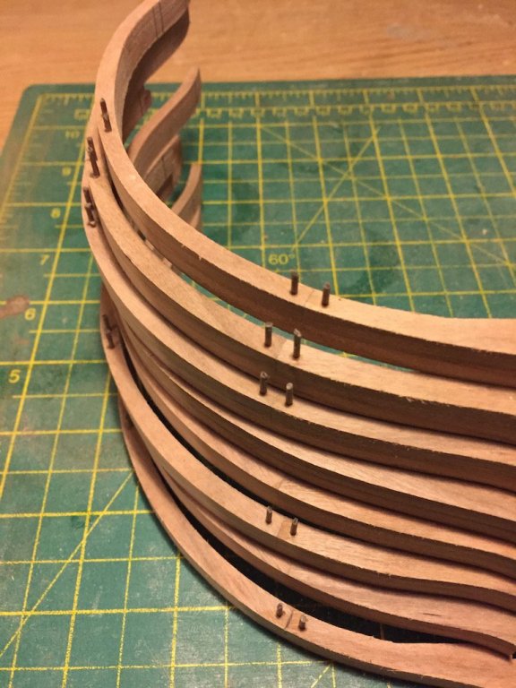
Well finally I have gone a few more steps forward.
And glued together all frames.


Finally, also is ready for sanding.
- Captain Poison, Canute, MEDDO and 15 others
-
 18
18
-
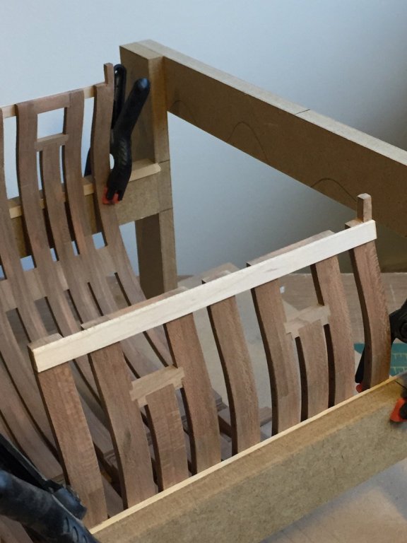
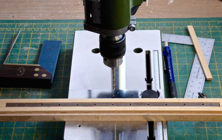
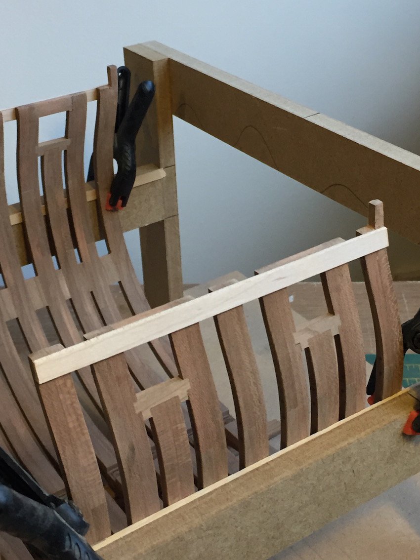
Hello everyone.
Decided to slightly update my work.
I made Tree nails for frames
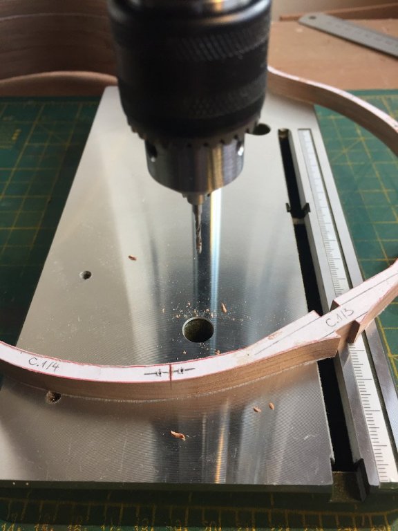 .
.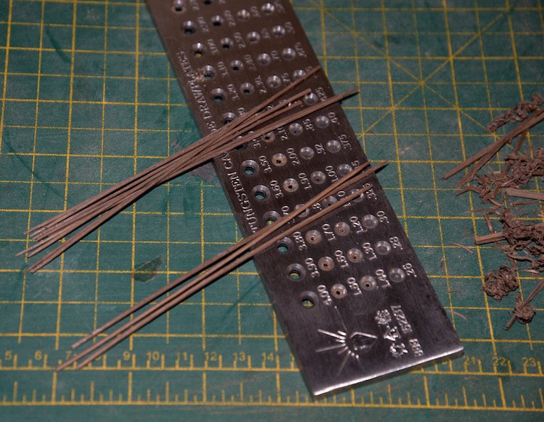
Clean all the paper. And recommendation of using Fixo gum glue had perfect.
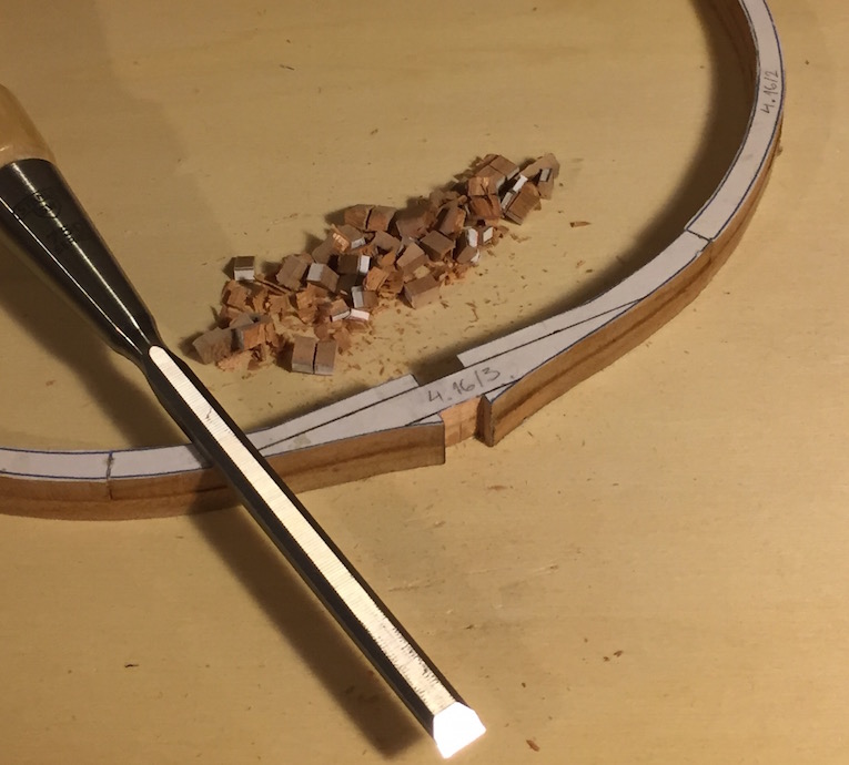
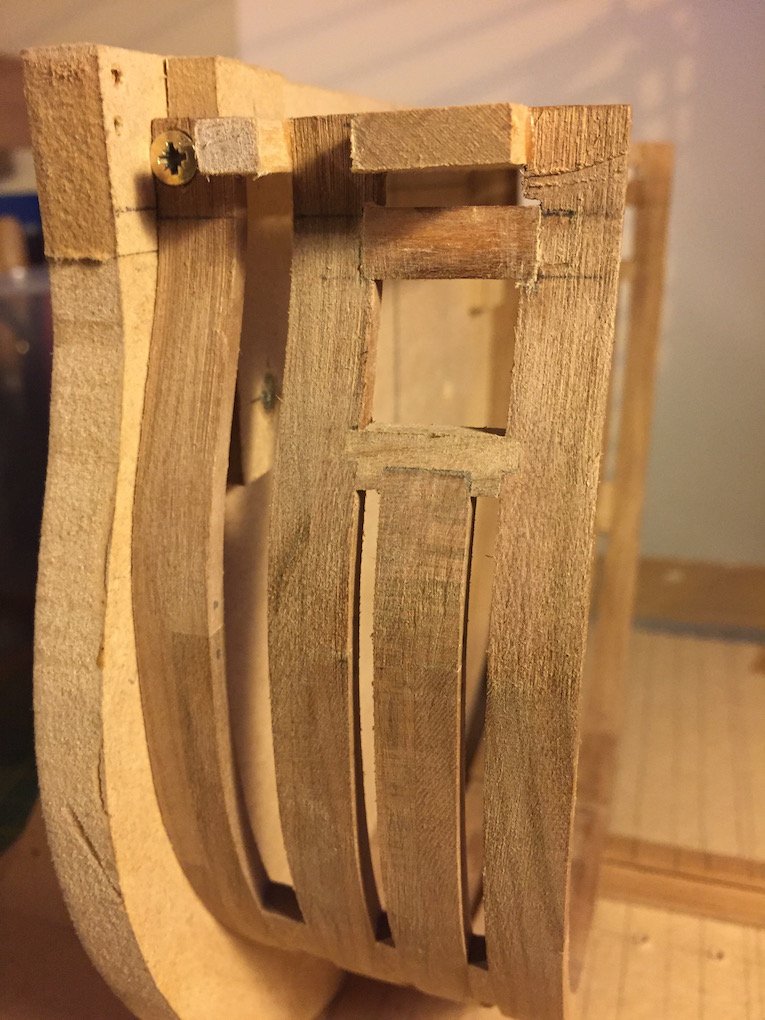
Before assembling cut out recess for gun ports.
And finally start assembling frames.
I slightly redesigned Gun port sill. To create more stringent joint.
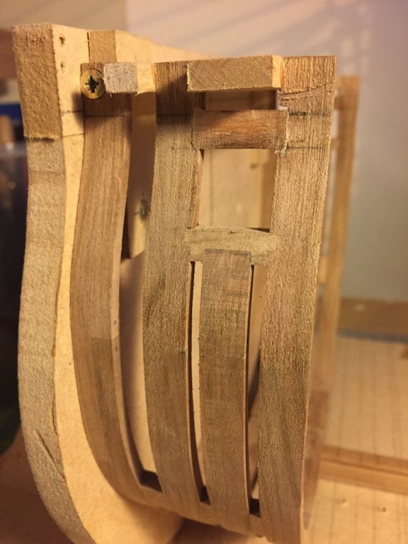
At the moment it would all.
But to be continued.
- Ondras71, MEDDO, shipcarpenter and 12 others
-
15
-
Thanks Chad.
Talking about treenails .I just wanted to know if there are any specific dimensions where they need to bee located. How many their really are on frame?
In any case it is too late. Because I decided to improvise.

Then next project i will found out how to do it more correctly.
Yup. About set filling / spacer block i think that on the component between frames. Do they also have any specific dimensions and sizes where they need to bee located? Did real ships had them If not is it necessary to use them?
-
-
Happy new year every one:)
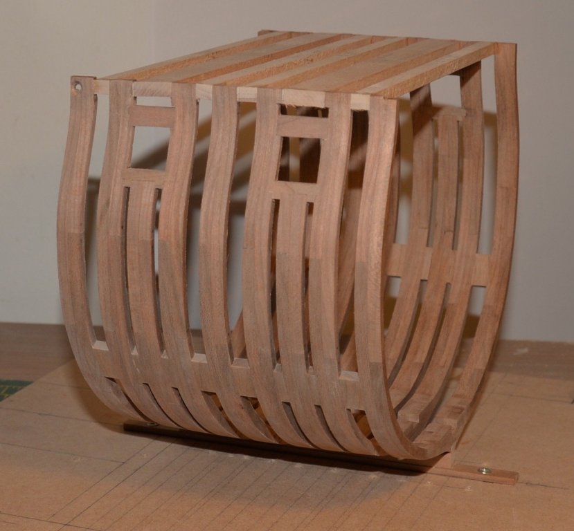
I also wanted to show the my progress of H.M.S.Triton .
For me it all happens slowly. But not going to give up.

When all the parts were cut. Glued it together I had no problems.
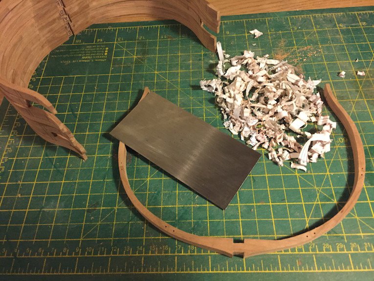
Once the frame had glued together. Cut out recess for Kell and Kellson
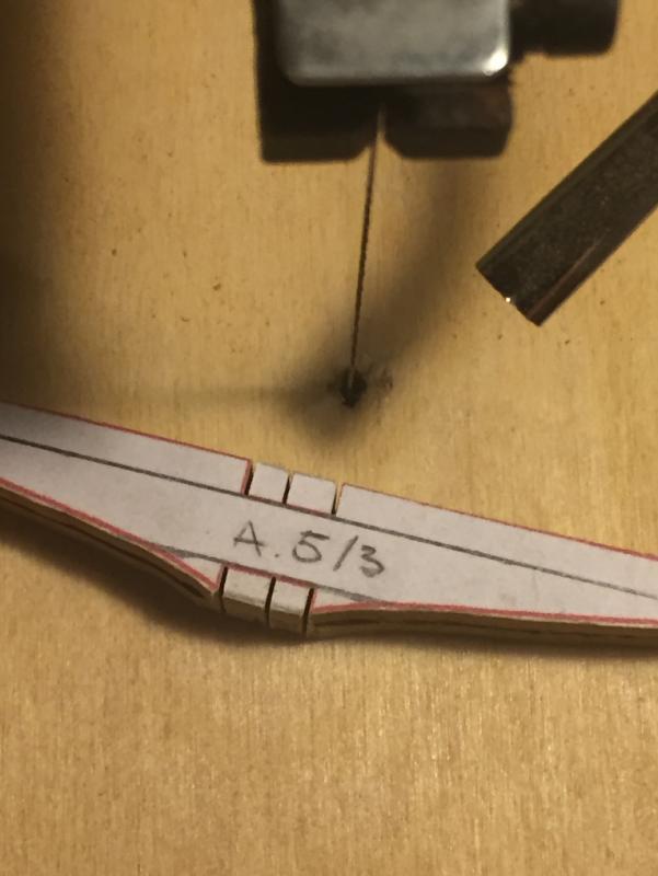
With file mace good frames straight part and recess for Kell.

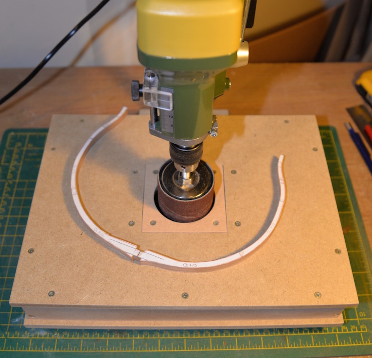
With Drum sander sanding inside the frames.
At the moment that's all. I started working at the tree nails for frames.
But I wanted to ask. Are there any direct information about that?
In looking at the work of others. It seems that everyone is doing it differently.
P.S.
Sorry for my English. Because I do so just learning, as ship modeling
-
-
-
Hi All.
Finally I chose to start this project. Like many others this will be my first attempt to scratch building. But I hope that I will have enough skills and have time to finish it.
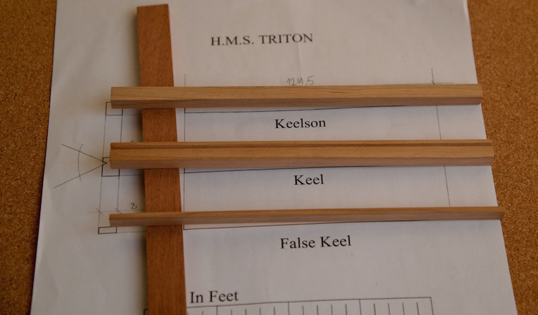
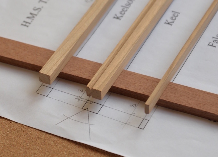
I completed the all kell parts, and ready for next step.
Like to ask for the rest of the plans


H.M.S. Triton Cross Section by Ainars Apalais - 1:48
in Cross Section Build Logs for HMS TRITON
Posted
Thanks Mtaylor for the reply.
I just looking for example more information about pump room measurements. Of course I can also copy other build models. That I think are going to do.
Because I can not find it in full-build plans:(
Of course A good option would be a kind of reference book.
Maybe you can recommend something...