Chuck
-
Posts
9,701 -
Joined
-
Last visited
Content Type
Profiles
Forums
Gallery
Events
Everything posted by Chuck
-

Sail design for 18th-century longboat?
Chuck replied to Cathead's topic in Masting, rigging and sails
That is correct. It is a very faithful representation of the tiller horse arrangement but just a little later than the contemporary model I used as inspiration. Both are correct. I guess at some point they said to themselves...."this arrangement with the sheet and tiller is stupid. Why do we insist on using it when all we have to do it make it go over the tiller" One can only speculate why they used it in the first place and why for so long when it seems pretty clear it was in fact not a smart thing to do. -
Sail design for 18th-century longboat?
Chuck replied to Cathead's topic in Masting, rigging and sails
Gregory...because that was the way it was done. Guys, my final word on this for those who are interested ....its just my opinion. The horse above the tiller is also correct as I mentioned. But having it below the tiller is very historically accurate for the period. if you read Lavery in the same book Page 228, and this is very important. ... It becomes clear that this arrangement as well as the alternative I drew based on the same illustration in May's book are both correct. You cannot dismiss the primary contemporary models. Even if the rigging isnt original...the horses were. Here is the quote from Lavery. I posted it once before when folks insisted the illogical arrangement was somehow fabricated by uninformed restorations. Or that I just made a horrible error based on lack of knowledge. But if you are building a mid eighteenth century longboat that is rigged, inspired by a contemporary example....the sheet arrangement is correct for the period. To alter it would mean you are correcting the problem, but this was a later development. Lavery said "The sheet, which controlled the outer corner of the sail, presented a problem, for it had a tendency to get in the way of the tiller. After the mid-eighteenth century this was solved by putting the horse across the transom to lift it clear, and allow the sheet to move from one side to the other without interruption." Lavery clearly agrees that this arrangement I used on the longboat kit ....however illogical....was used, and corrected later. Just as I do. But hey, its your model and you can always use a 20th century solution like the ones posted by Frank....or any others but that would just be a fanciful error based not on research but something else. I dont know what that is....but I prefer to stick to the period as faithfully as possible and always use primary sources along with the opinions of noteworthy folks who have spent their lives studying this stuff. You can always argue the dates....when did they make this switch-over? Were both configurations used and for how long before the earlier was abandoned. Lets examine the hard contemporary primary evidence.....or we could just make stuff up instead. When Frank writes, "What it suggests ( if these are not artifacts arising from folow-on restorations) is that contemporary models can't reliably be used as 100%faithful examples of actual contemporary practice." This might be true in a one-off incident but when you see something over and over again and then dismiss it readily, I think it might be more about cherry picking the facts to support ones own false theory. This is a dangerous road to go down in my opinion. For example, I am currently researching my next project (Chebacco Lion) and there are very few contemprary models of this early type of American fishing schooner. The windlass on the three models known to exist and several half hulls of the period is placed on the fore side of the foremast. There are also some drawings and paintings that show this detail. This was later changed to abaft the fore mast as can be seen on schooners like Hannah and Sultana. Rather than just dismiss this fact because as Howard Chapelle stated "the windlass would be very difficult to work and it isnt the best place for it".....I am going to place it where the contemporary evidence says it should be. Chapelle came to the same conclusion as did william Baker. Two very prominent naval architects and historians. Or I could just say that all of those contemporary examples are somehow just wrong and instead make something up that sounds good. Baker writes in his book about Colonial vessels and I find this particularly suitable for our conversation here "I sometimes wonder about these early designs, many of the fittings, including those that serve the functionality of the rig seem to be contrary to effective and efficient sailing practices. This can be seen in both the locations and materials used for them. There ineffectiveness can certainly be determined by comparison to modern-day fishing schooners throughout New England. The factual contemporary evidence however supports there widespread use despite the availability of better choices for material and examples of more effective designs predominant along the southern shores at the same time. One can only conclude that these practices were used because of local shipbuilder traditions and the willingness of these fisherman to faithfully follow regional customs and practice despite advancements elsewhere." Chuck -
Sail design for 18th-century longboat?
Chuck replied to Cathead's topic in Masting, rigging and sails
Roger There are exactly two contemporary models that show the horse over the tiller and that would certainly work. I mention in the instructions that a model builder could always show it that way. The horse is bent in a bell shape so it rises above the tiller and is a perfectly viable option as I mentioned above. I have never said that configuration isnt viable. You can see a wonderful drawing of that configuration in Lavery's Arming and Fitting on page 226 I believe. I have also attached a drawing of that contemporary alternative below. The other more widely seen contemporary option is shown on the contemporary model examples I posted in the previous post. Their are dozens of examples shown that way including contemporary paintings and drawings and is more prevalent however. Yes to all of us today it may seem illogical but there is so much proof available that it was indeed set up that way. It is absolutely NOT wrong. But even more problematic are the examples posted by Frank. There is ZERO contemporary evidence that any of the modern configurations shown were ever used in the eighteenth century. It is just plain wrong for the period. However ... Based on all of the contemporary evidence the two other configurations are good to go. The later is absolutely more prevalent although to us today very illogical. But just because we dont understand it.....doesnt mean that using 19th or 20th century practices on an 18th century longboat is a better idea. It is just all-together wrong and as mention there is ZERO evidence to support it..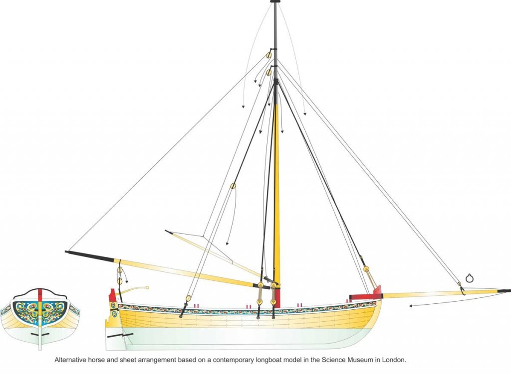
-
Sail design for 18th-century longboat?
Chuck replied to Cathead's topic in Masting, rigging and sails
I know it sounds impossible and by most modern standards and practice it is. But that doesnt negate the fact that 90% of contemporary long boat models (some with original rigging like this one) show the sheet configured this way below. There are fewer examples showing the horse over the tiller......but as far as historical accuracy, this is not incorrect as it is a primary source. I dont pretend to disagree for arguments sake but I have seen folks understandably realize the difficulty that Frank brings up. BUT, the contraptions and configurations the model builders then place on their 18th century long boats as a logical fix have no basis in historical fact. In fact they are just plain wrong for the period. To rig an 18th century long boat as described in the photos above would not at all be correct. This may not make sense to us as pictured below but it is very clear that this is indeed the way it was configured on many if not most occasions.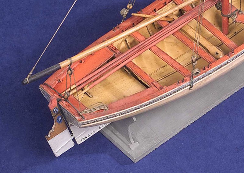
-
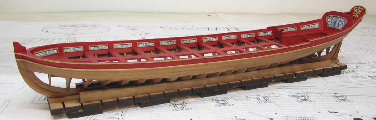
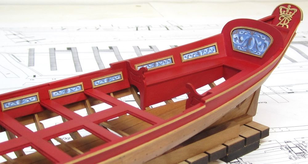
Thanks guys....this last iteration will do fine. It takes a long time to create these friezes. I am very happy with the latest results and dont wish to paint another set. But for those who are thinking about buying the kit.....the possibilities are endless. I am looking forward to finishing up the inboard details real soon. Then its the home stretch.....for the hull anyway.
- 269 replies
-
- 12
-

-
- Queen Anne Barge
- Syren Ship Model Company
- (and 1 more)
-
Right there with you Greg. I guess I couldnt fight my Italian urge to be extra bright and gaudy. But yes, after a day or so I re-did the friezes making them a more subdued blue gray. This is more in keeping with the contemporary model I used as a reference. Comments are welcomed !!! Any thoughts ???


- 269 replies
-
- 38
-
-
- Queen Anne Barge
- Syren Ship Model Company
- (and 1 more)
-
Thank You Marvin at Scale Hardware for sponsoring our forum. I am sure everyone will love what you guys have to offer. Tiny bolts and nuts.....rivets and everything in between. Visit there online store and website and browse around. Join me in welcoming them www.scalehardware.com
-
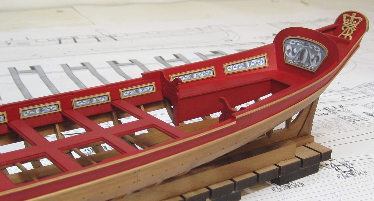
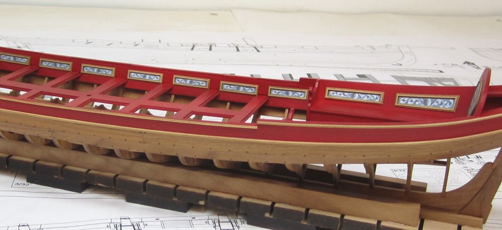
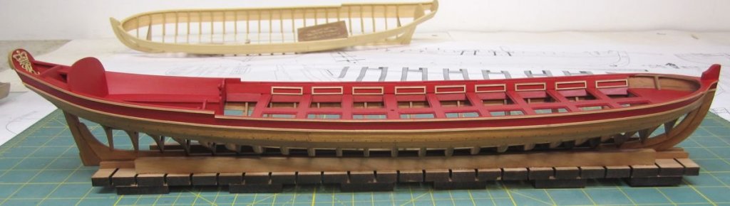
Thank you very much for the likes and comment. The panels were completed and glued into position. You could leave them like that with just the empty panels which has been seen on many contemporary models. In this case I chose to insert printed friezes into them like the contemporary model shown above. I actually patterned the same same frieze design from that contemporary model and used it on my prototype. What do you guys think. I will be working on the step into the stern sheets next and then started on the outboard details again shortly after. Chuck
- 269 replies
-
- 40
-
-
- Queen Anne Barge
- Syren Ship Model Company
- (and 1 more)
-
Mystery Model - Question for Moderators
Chuck replied to David Lester's topic in Wood ship model kits
Sure thing....I am pretty sure someone will recognize it. -
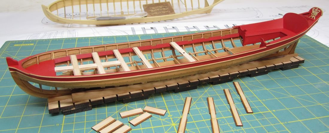
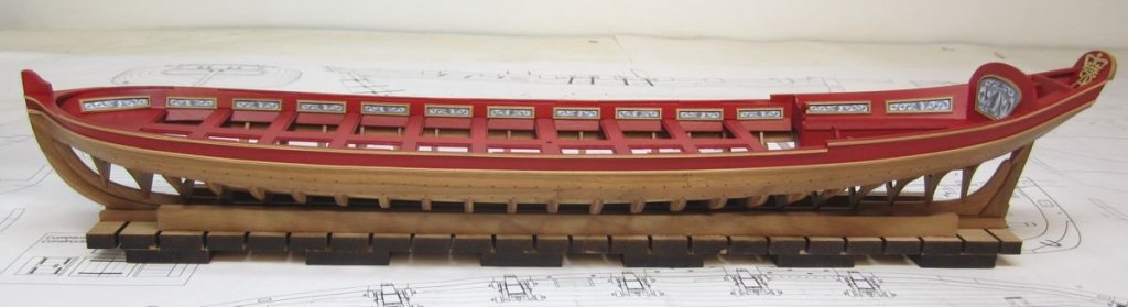
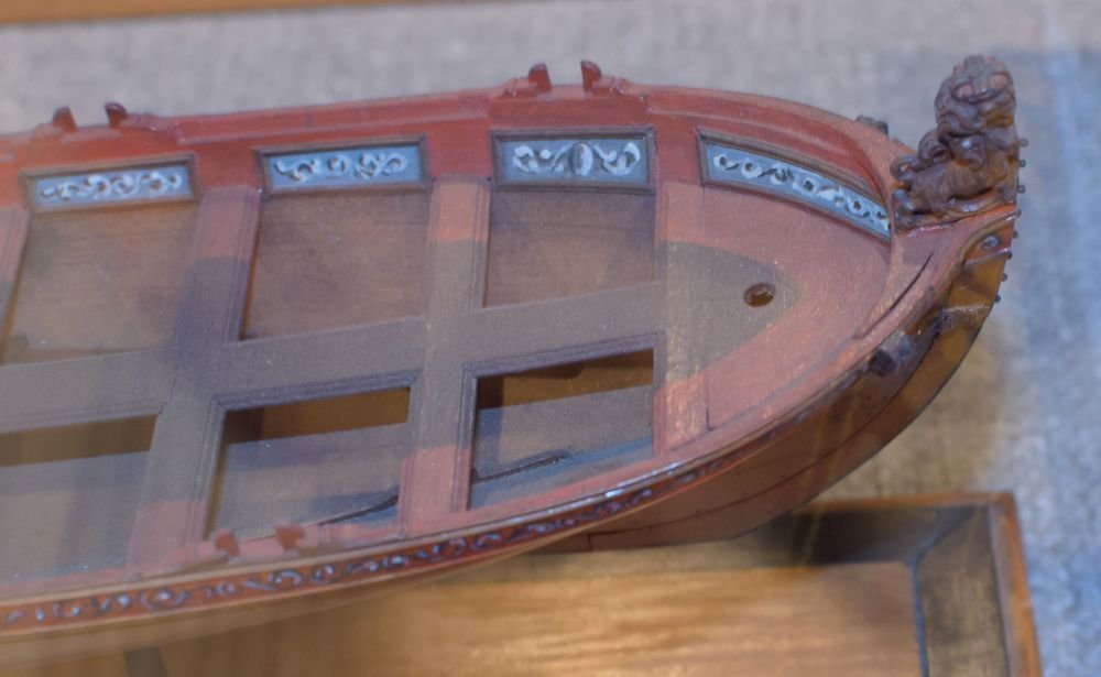
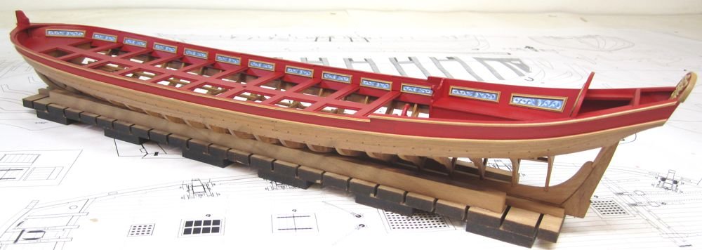
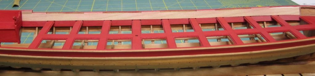
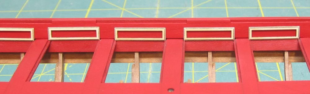
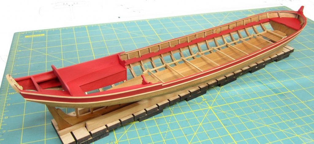
Thank You Gentlemen.... I installed the thwarts and painted them. Then I began planking the area above them. I glued one laser cut, pre-spiled plank above the thwarts. The interesting thing about this plank is the fact that it doesnt extend up to the shear. It in fact is only wide enough to just touch the bottom edge of the caprail. This leaves a consistent rabbet or ledge all around the caprail. Then smaller lengths of laser cut wood the same thickness of the planking are strategically placed on top of this plank. These small strips do extend to the sheer and are sanded flush with the top of the cap rail. These pieces are ONLY placed where an oarlock (tholes) will be located. And they alternate port to starbord as is typical with single banked barges. This can be seen clearly in the photograph supplied of a typical contemporary model of a barge. Once Painted I couldnt wait to try out my laser cut panels. I didnt even wait until all of the interior planking was completed. This was a real pain to do on the pinnace model and those of you who have built that kit can probably agree. For the pinnace kit, in order to create the panels you had to first scrape some molding strips to create the fancy profile while keeping the strips very thin. Then each panel was made by hand where you had to miter each corner of every square panel. It took dozens of hours over several days. To alleviate this pain I tried to design laser cut panels with a fancy molded edge. It was of huge importance that this work and look good, in addition to the time savings I was planning on including the friezes in this kit. If they were laser cut and a consistent size I could include them no problems.... I was pleasantly surprised at how well they turned out. What took dozens of hours over several days on the Pinnace took only a half hour to do on this barge. I have just tested these in position and they are not glued into place yet. That will be done later after I finish the inboard planking. The panels are very delicate at only 1/32" thick. So I sanded the top surface to clean it up and make it bright. I used a light touch with 320 grit paper. Then I lightly sanded the outside edges only. I didnt bother with the inside edges because the panels are too fragile. I also didnt bother trying to remove the laser char from the etched fancy profile. After sanding the edges lightly the darker char actually emphasizes the profile and looks rather good. I would hope you all agree. They are made from boxwood and once finished with wipe-on-poly they look quite nice. Friezes printed on paper will be inserted into each panel much like the contemporary model shown above.
- 269 replies
-
- 38
-
-
- Queen Anne Barge
- Syren Ship Model Company
- (and 1 more)
-
Based on the size of your jollyboat it looks a tad large for its use on a Brig like Syren. This is probably why it may look awkward along the transom and not line up properly to be hanged. I would have made one about 15% smaller. Although Brigs like wasp were known to carry an 18 ft Jolly or Yawl, I probably would have gone with a 16 footer, if not for anything else but asthetics hanging from the davits. But there are several examples of how to hang such a jollyboat off the stern. Here is a simplified version on a model of Syren. You might do a google image search for the Niagara as well because if memory serves me correctly the Niagara routinely carries one stored back there on its voyages...I am talking about the replica.
- 227 replies
-
- 5
-
-
- syren
- model shipways
- (and 1 more)
-
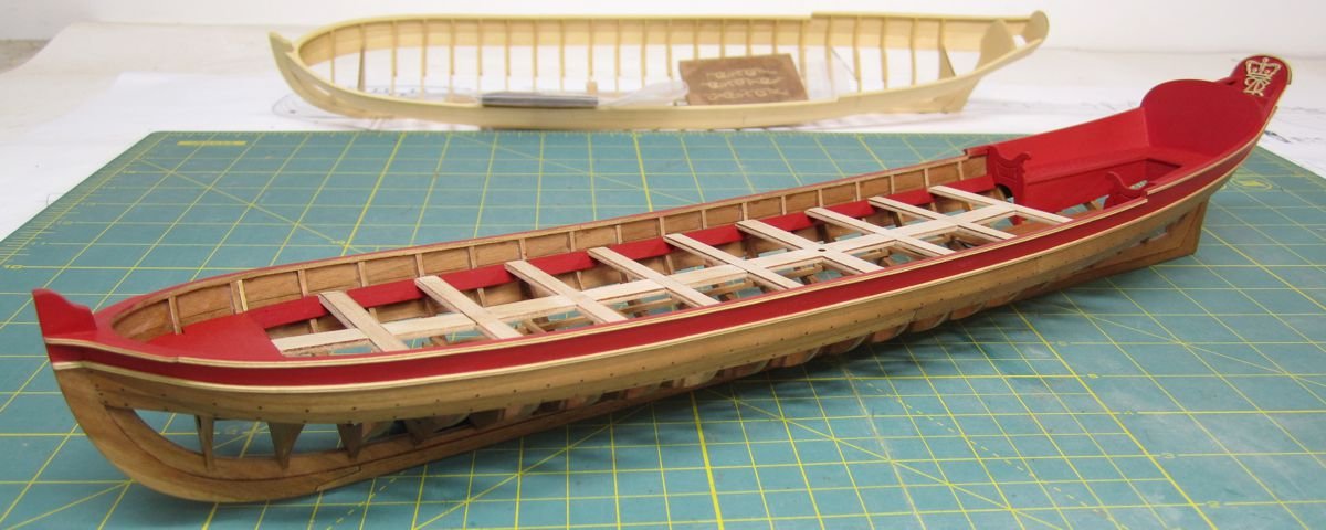
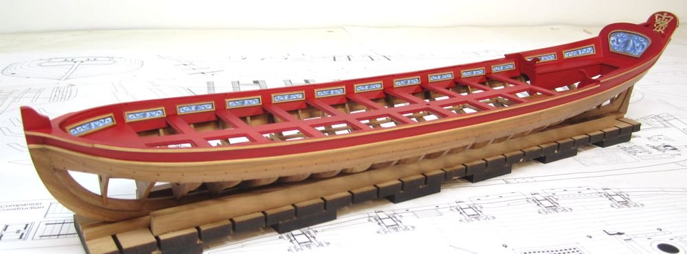
All of the thwarts are now in place. But no glue yet. These are all just test fit. The tweaking is completed and all of the pieces seem to fit together with nice tight joints. I will glue them into place next and paint them. She is finally getting there.... Once these are done the only major construction left is the remaining inboard planking. After that its just the fancy bits and little detailing which makes it all come together. The paneling and carvings ect.

- 269 replies
-
- 27
-
-
- Queen Anne Barge
- Syren Ship Model Company
- (and 1 more)
-
Thats pretty neat.....use the groups name in your title. I am sure there will be many interested.
-
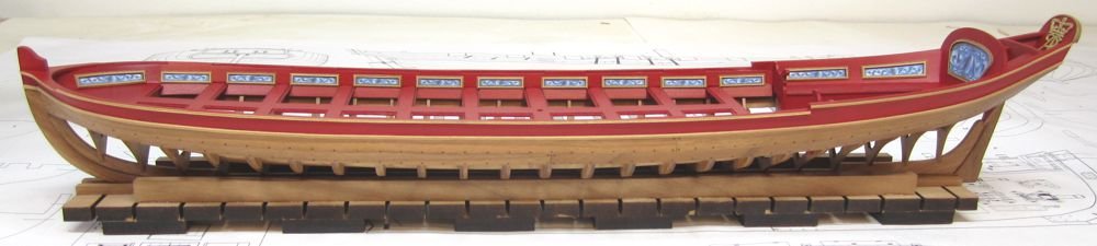
Just an update on the barge prototype. Work has continued since I got back from Annapolis. It was quite inspiring. Compare some of the images of the contemporary barge model. It was very helpful being able to examine it close up. The riser and stretcher timbers have been added. All are laser cut. Then the forward platform. I am now test fitting the thwarts in position. These are all just dry fit. No glue.....yet. The thwarts are all laser cut with etched trim. There are little notches laser cut on both sides to accept the center board between each thwart. I will dry fit them all together and then glue them in afterwards. I want to ensure a proper fit with thaat center board going straight down the center. Once I know that is OK I will glue them in and paint them. Or paint them first...I am not sure yet. Chuck

- 269 replies
-
- 38
-
-
- Queen Anne Barge
- Syren Ship Model Company
- (and 1 more)
-
Nicely done Russ. Planking is shaping up. The run of planks looks spot on.
- 420 replies
-
- 1
-
-
- captain roy
- lugger
- (and 2 more)
-
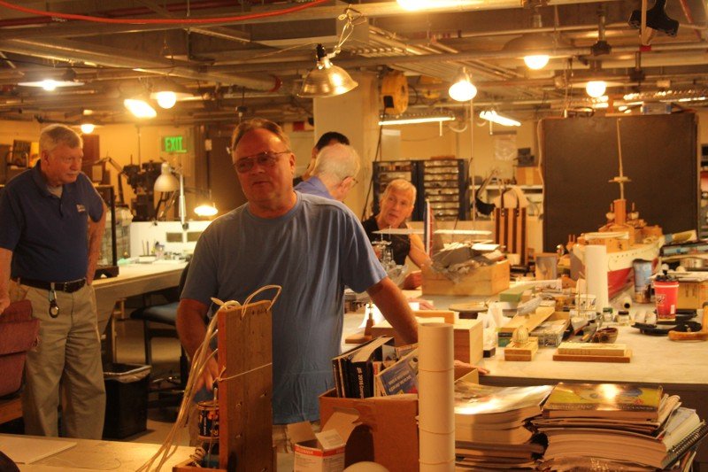
Thanks guys. Greg, Grant wasnt there that day but Don was. He spoke to our group for a while and we hung around the shop with the other guys who volunteer. He was off to Europe to visit the NMM that afternoon. Most everyone had been there many many times before but we took our time and some of the other guys accessed other buildings and models too. A very nice time had by all. Here is a view of the guys in the shop with ongoing restorations at the Academy. I believe that was a builders model of the Maine on the right. Chuck
- 269 replies
-
- 22
-
-
- Queen Anne Barge
- Syren Ship Model Company
- (and 1 more)
-
All you really have to do should you want a size I dont have listed is let me know before you order....I can always make the sizes you need. I just dont stock them because only a few people actually build that large and it doesnt pay to stock them as regular items. If you need them laser cut without the sheaves so you can replace them with with your own metal working sheaves that is also possible. I will just omit them. And by the way....for those that do need externally metal stropped blocks like cathead blocks for anchors, all you have to do is flip the orientation of the outside shells of each block. With a bit of creativity these will serve many purposes. I just cant stock them in every variation but hope that everyone can easily look at the parts and build them as they need them. These are easily turned into working blocks by removing the laser cut wooden simulated sheave before assembly and inserting a brass sheave in its place. Chuck
-
I just returned from a weekend in Annapolis at the Naval Academy. About 20 of our NJ club members went down and it was a wonderful time. Several of us brought our wives and girlfriends. We enjoyed lunch and dinner and a nice tour of the academy including its workshop where several models are being restored. Its always a pleasure to see my friends at Preble hall and they were spectacular hosts. I went down with one important goal besides enjoying the great company. I knew of a barge model that I wanted to photograph in detail from the same period as my Syren project. I am about to get back into the shop to work on my prototype. Here are some photos of that contemporary model. Note that it is NOT Clinker planked and it is completely planked. There are many other details of interest which will be pointed out as I continue my project. Here are some of the folks from our motley group ship modelers. A bunch of the other guys are missing from this photo, including my wife who was walking around the academy (probably shopping in town) at the time and in the museum. We are so fortunate to be such close friends and try to do this type of thing as often as possible. Where are we going next guys?!!!! You know many of these guys too. They are active MSW members. and some of the photos of the barge below....I have many more (thanks Mike) and will post them in an album and in the kit instructions. This model is circa 1705...Just beautiful!!!

- 269 replies
-
- 32
-
-
- Queen Anne Barge
- Syren Ship Model Company
- (and 1 more)
-
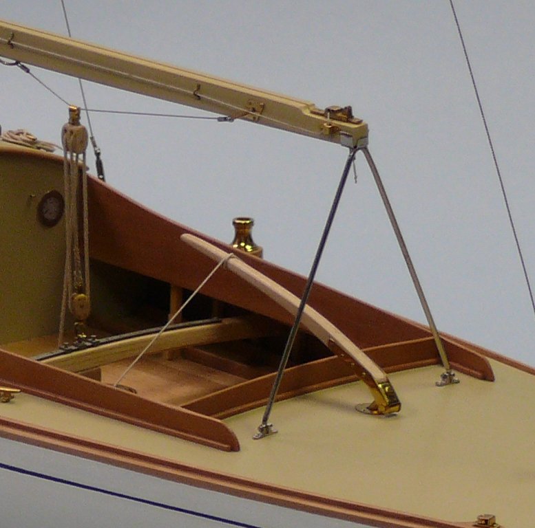
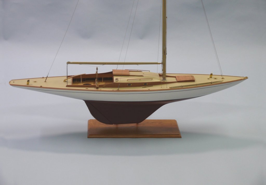
Here is an image of one of my blocks in use on an early yacht model. The model was built by Steve Wheeler. Its quite beautiful. Steve is a master craftsman with these models. It shouldnt be too difficult to make the number of blocks you would need. Its a far cry from the hundreds of blocks required on a typical "sticks and strings three master"
-
We sell plenty of internally strapped blocks at syren should you choose to go that route. Syrenshipmodelcompany.com Chuckj

-
Yes indeed....it is impossible to bend that severe a curve on the end of the strip. The curve was made closer to the middle and then the excess snipped off and discarded. If you achieve the proper curve you will need very little pressure if any to make the plank rest against the frames without any lifting. If it lifts at all your curve is incorrect. With such thin planking, you may not have to apply much heat to bend it the other way and also give it a bit of a twist. I have written a very detailed instruction for the barge here. http://modelshipworldforum.com/resources/Barge instructions.pdf on how I bent and twisted each strake. Maybe it will be of some help.
- 156 replies
-
- 9
-
-
- pinnace
- model shipways
- (and 1 more)
-
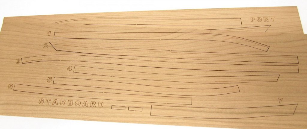
Planking these small boats is a challenge. Keep in mind that the curve on these planks was rather short and abrupt. I dont know if this helps but the shape for my latest barge is almost the same and these pre-spiled planks are a good comparison to the shapes you will need on the pinnace. Look closely at plank 1 and 3 and 5 which show the curved end for the bow quite well. Note how its an "s" shape overall. Because the curve needed is so tight at the bow being over only 2" or so it is probably easier to find and spile the shape and then cut from a sheet. You should give it a try on those strakes at the bow at least and for the first four down from the sheer. Keep in mind that this is a clinker hull but the shapes of the planks are the same. Chuck
- 156 replies
-
- 8
-
-
- pinnace
- model shipways
- (and 1 more)
-
Anyone can always contact me if the need some clarification.....and PDFs.
-
Now you know why I am doing my own kits and projects.....LOL I feel so bad about this guys, I hope you guys get it sorted out with Expo. Chuck