Chuck
-
Posts
9,701 -
Joined
-
Last visited
Content Type
Profiles
Forums
Gallery
Events
Everything posted by Chuck
-
 The stuff is back......scale hardware was bought out by model motorcars https://model-motorcars.myshopify.com/collections/small-parts-hardware/bolts Greg you can take a deep breath now!!!!
 -
There is a preview.....In the editor as you are typing your post.......the very last icon. The one that looks like a piece of paper with a magnifying glass. In fact, just hover over every icon in the editor bar to see what you can do. Chuck
-
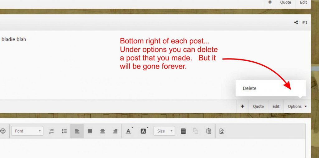
Yes indeed......trust me we now understand.......... OK....to delete a post you made (NOT A TOPIC). click the options dropdown on the lower right of your post. You will see delete......it will NOT be gone forever. It goes to a holding bin for one month and then it goes away forever. It will ask you if you are really really sure...... Most important...when you want to delete a WHOLE TOPIC you started. See the four buttons above each topic .....at the top of your topic, these control your whole topic and NOT just a post. You can ignore a topic etc. But if you select Moderation Actions, you will see "delete, be very careful". This will delete your entire topic, including anyone elses posts that were made in it. You will see a pop up that ask you if you are really really sure about this.... If even after all of that, you deleted it by mistake, the topic can be restored within a short period of time if you contact an admin. Be sure to tell them the name of the topic and what forum area it was originally in so they can put it back there. But after one month if you dont contact us it will be gone forever.

-
Will do......and give me a moment to do some screen shots and show everyone what is what. Remember......delete a topic and we can save it if you let us know soon. Delete any individual post and its gone forever. Back in a few minutes with some screen shots. Chuck
-
OK....as you guys know, we turned off the ability for members that allowed you to delete your own content. We did this because two or three members deleted their build logs by accident. They were not recoverable. However, by turning off this feature, it also disabled a members ability to delete the last post they made if they made it in error. Whether on their topic or someone elses. These two features are not separate in the software. So to be clear, either you can delete both topics and the last post you made or nothing at all. I understand how this can be a pain in the butt. If you post something and want to delete it, you cant right now. You can only edit your last post and remove the content. Leaving a blank post. Then you would have to contact a moderator or staff member to have us delete it. Or we would have many posts that are blank or that you write..."removed content". This is not ideal and quite sloppy Why am I repeating all of this here? We may have a solution. We have mitigated this somewhat. We have created up a feature currently only available to mods and admin. When we delete a whole topic, it doesnt actually get deleted any longer. It will be moved to a new "trash can" topic hidden from view. Only a moderator or and admin can delete topics that end up in this trash can. Until we do delete it forever it can always be moved back to the forum it came from. I guess you can call it a restore feature. BUT...this feature only applies to complete topics. NOT individual posts. So when a post (like one you had second thoughts about making on a topic is deleted) it will be gone forever. This also applies to us mods and admin. When we delete an individual post....its gone forever. SO.....what I am saying is.....we can now turn the feature back on that will allow you delete your own topics that you started and posts you have made. But remember....individual posts are gone forever. Only complete topics are sent to this "recoverable trash can" Should I turn this feature on for members????? Pros. You wont have to worry about deleting a complete topic or your build log and it will be gone forever...... you wont have to bombard the staff with requests to delete topics or individual posts....which judging from past activity happens very often. When you dont tell us to remove a post you made in error we will have useless posts emptied by each member hanging out on the site. This prevents that. Cons.....if you do mistakenly delete one of your topics, you must recognize soon that you did delete it by accident and tell a staff member to restore it.....we wont leave topics in this trash can forever. We will empty it from time to time. So you cant ask us 2 months later to restore a topic. Once again......posts are gone forever....but a staff member will be able to restore your accidentally deleted topic. Do you guys feel comfortable with this. If so I can turn it back on for a trial run. And I will post some screen shots of where you can go on a post to delete it vs. deleting a full topic. But I fear even with instructions some of you will mistakenly delete something..... and once again....posts are gone for good. BUt a complete topic you delete will now be restorable. this is something we set up as a direct fix after several members mistakenly deleting their build logs with no easy way to recover them. Now they will be recoverable.
-
It makes the ship look larger from a distance.....plus just plain old decorative as well. Chuck
-
Hull plank length
Chuck replied to Mau's topic in Planking Techniques's Click Here for Topics dedicated to planking!!!!
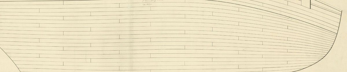
We are actually fortunate to have many planking expansions for royal navy ships. The original drafts of such inboard and outboard expansions are available and have much of the info you need. For Cheerful in particular, both the inboard and outboard expansions exist showing the width, thickness and length of every strake. The plans I developed for Cheerful are an exact match using that info. Its one of the reasons I chose Cheerful, the original documentation is so complete. Here is the outboard hull beneath the wales for Cheerful as an example. Finding the measurements is a snap. The length varies from 23 - 25 feet mid ship. There are however a few when needed that are longer but its an exception.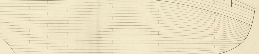
-
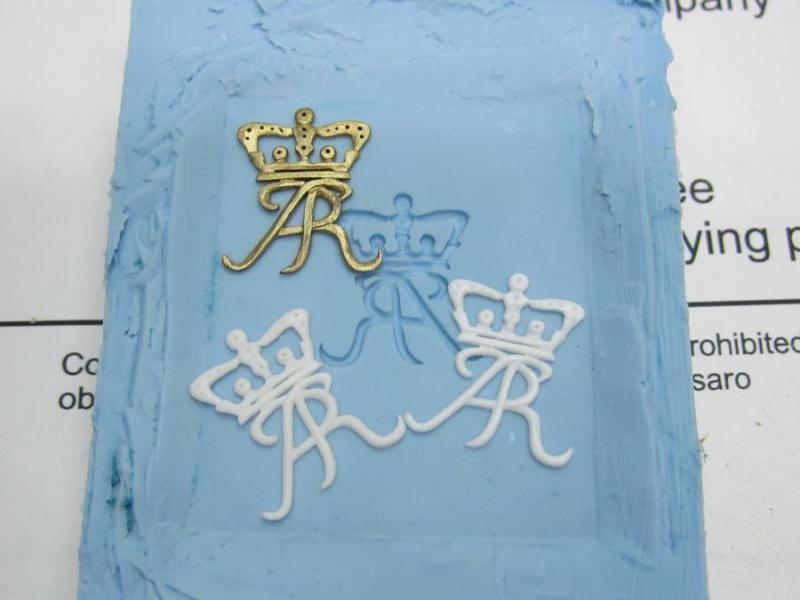
Just an FYI, This tutorial was about making simple one piece molds for flat-ish small decorations on ship models. Like gun port wreaths etc. There are also more complex two and three part molds for making fully round parts like cannon or a figurehead. When time permits I will make a similar tutorial based on my experiences. I will also continue to try new material and brands. For example, as soon as my gold dust gets here I will try and make a gilded example of the monogram used in this experiment. I am just waiting for it to arrive in the mail. But everyone should add there experiences here for simple one piece molds so we can start compiling more content and info for everyone. We will try to bring everyone more tutorials like this for other things.....maybe soldering, or blackening, or very soon I will be sculpting additional decorations for the barge kit prototype from Sculpey and will create a similar topic about that. Chuck
-
Thank you. The resin gets pretty rigid in larger pieces. The thin pieces are fairly rigid but have some flex if you want it to. For a day or so after de-molding....certainly for a few hours after they are somewhat flexible and can be bent to conform to some bend. But they will firm up. There are so many different kinds of resin that you can buy some that is extra rigid and some that are extra flexible. This stuff I used is just the regular stuff though. Chuck
-
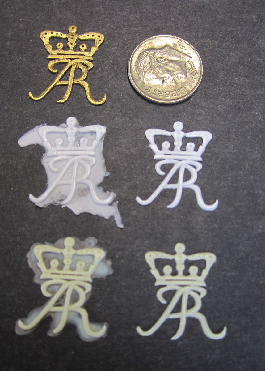
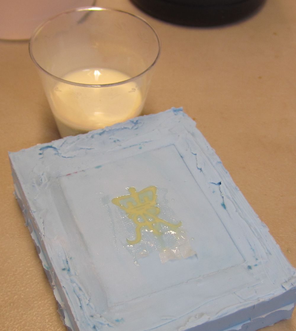
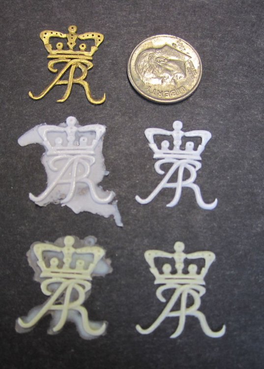
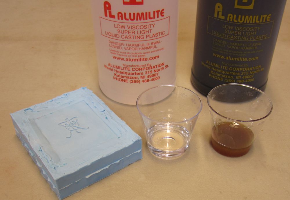
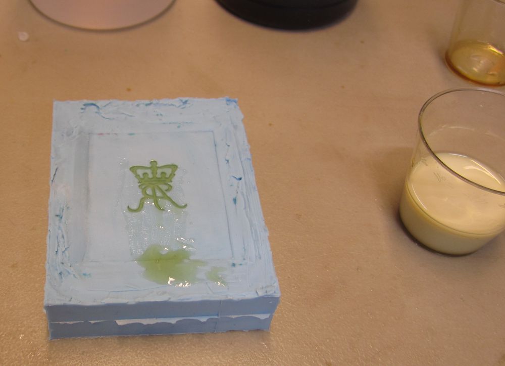
Prepare your mold for pouring There are many ways to do this but let me write about how I was taught. Before you pour the resin in the mold, I usually dust it with talc or in this case baby powder. This gives the cast part a nice finish and prevents bubbles from forming along the molds surface. The bubbles will slide away to the surface or the back of the casting. I will brush off the excess talk and make sure there isnt any clumping in the detailed areas of the mold. The photo above shows the baby powder after I prepared the mold. Next to it is some Alumilite casting resin. There are many different types. This is their regular stuff. It has an open time after mixing it of 90 seconds and cures in about 15 minutes....usually....I will explain this more later. I also made some castings using the Micro-Mark resin which has an open time of 3 minutes but cures in 40 minutes after pouring it....normally. Both are the same as far as being a two part mixture 1 to 1. Equal parts of A and B. The Alumilite cures tan while the Micromark cures white. There are many other colors and many other open and cure times available. Just pick one that you are comfortable with and like after giving it a try. I will say that short open times before pouring are tough.....you do feel rushed. But then you will have to wait less time while it cures. In the photo below below you will see that I have poured equal parts into disposable plastic shot glasses. They are just 2 oz. Our parts are very thin and tiny and using larger containers is problematic and wasteful. I have a wood scrap strip to stir it up after mixing the two parts together. A few points or tips worth mentioning. Make sure it isnt very cold where you are working on this stuff. The resin should be room temperature. This is true of the mold you are pouring it into. Good at room temperature or even better yet....warmed up a little. It cuts down on the cure and demold time. If its winter and cold I might sit the mold on the radiator for a minute or two. I do gently stir both parts before pouring them into their sep. containers. Make sure you dont agitate them to form air bubbles. Pouring the resin Next I pour one part into the other shot glass. Stir it up well but again be careful not to form bubbles. Remember that I only have 90 seconds before it starts to really harden up. So you must work quickly and stir for 20 seconds and then pour into your mold. Pour is not the correct word....these decorations are just 1/32" thick or deep in the mold. The design has small thin 1/32" wide elements. You just cant pour it on top of the mold. You have to carefully drip it into the mold as best you can. You will no doubt over fill the mold. But then take a wooden scrap stick and squeegee the excess to one side so it is mot a huge puddle. The parts would be too thick otherwise and require lots of sanding and cleaning. The photo shows the resin poured.....note how I squeegeed the excess to the bottom. Also note the dark color in the mold. It will cure to a light tan. Also note in that same photo how the shot glass has already cured lighter and is hard. This is less than 2 minutes after mixing both parts together. You will also notice that the resin in the mold is not cured yet. You see, thinner parts like this will take substantially longer to cure than the larger volume in the shot glass. In fact, it took a full 40 minutes for these thin fragile castings to cure in the mold. This is true even though the resin is sold as a 15 minute cure. As ship model parts are so small and thin they will take much much longer than they advertise. The resin heats up when it cures and that is why warming the mold up before pouring will speed the process up somewhat. It is also why a cold mold and a cold resin will take a very very long time to cure. So you have less time to pour knowing this but will need to wait longer to de-mold small parts. Keep this mind when you are selecting which resin to buy. After 40 minutes.....see below Ready to remove the casting The resin is very hard to the touch with a toothpick....ready to de-mold. Forty minutes later. Flex the mold a bit and carefully pry and work the casting out. Now when the casting is released it will look messy because unless you are pouring a huge part, these little ones will over flow a bit. So looking at the photo below, you can see the two tan castings on the bottom row (Alumilite) and the two white ones above those (Micro-Mark) The first of each pair show how they look right out of the mold. The flashing and excess should be removed. I usually rub them on a flat surface over some medium fine sandpaper. This will at least take the majority away. It doesnt take long to do but imagine if I didnt squeegee the excess away after I initially poured the resin into the mold. The example next to those in each pair is after I cleaned it up. Above them both you will see the master which was painted gold leaf next to a dime to show the thickness and size. The ones shown below are the MicroMark resin along with the master..... Both brands of resin show great detail.....even fingerprints. I cant say that either is better than the other except that I enjoyed the longer open time of the Micro-Mark resin. But Alumilite has different resins with more open time as well. So does Smooth-on mentioned earlier in this topic by some members. Like the mold rubber, this resin will not keep long. It doesnt have a long shelf life so after 6-9 months test it in your mixing shot glasses without pouring it into a mold....just to see if it still cures. Keep it in a cool and dry place. Moisture is bad for resin.....put the caps on tight.


- 18 replies
-
- 11
-

-
Thanks Ken I am very familiar with smooth-on products. They are very good as well. The tutorials are really good to.
-
HM Cutter Cheerful 1806 by Erik W - 1:48 scale
Chuck replied to Erik W's topic in - Build logs for subjects built 1801 - 1850
Beautifully done!!! I cant see any issues at all. I love the color and the photography is top notch. -
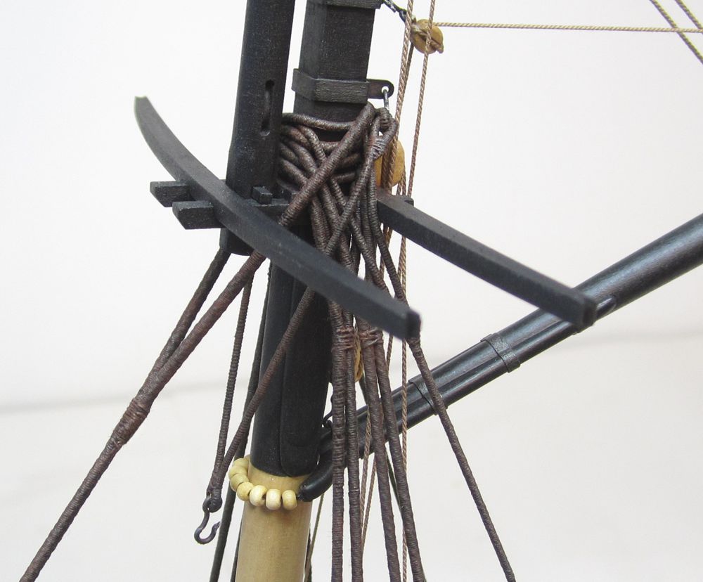
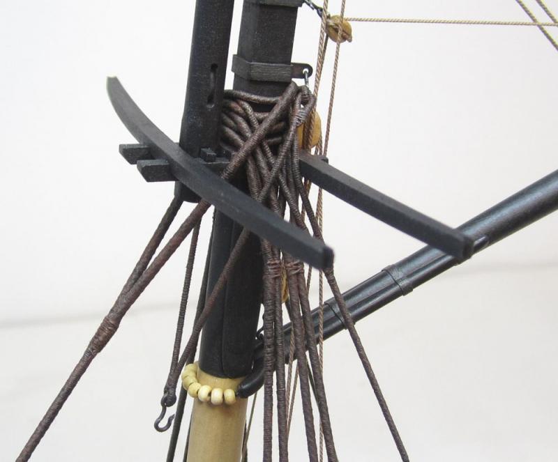
With regard to the lifts....you will often see a cutter rigged with the lifts going through the shrouds. Here is a contemporary model with original rigging..... Note that the lifts pass between both shrouds. Others do in-fact have them in front of the shrouds also but this is NOT always the case as you can see here.
-
Common blocks & the like for 1:64 scale ships
Chuck replied to FlounderFillet5's topic in Masting, rigging and sails
Thank you very much. -
Common blocks & the like for 1:64 scale ships
Chuck replied to FlounderFillet5's topic in Masting, rigging and sails
I am not really sure as I havent built them all but those I have worked on were OK. Its just that all MFGs of commercial blocks in kits come from Europe. They are metric so the sizes are off from the start when looking at an MS kit. So when you build an American ship or an English one where the plans show the blocks the correct size...you get whatever the closest MM metric block made in Europe. So if it calls for 3/32" you will get a 2.5 mm block. Which was made slightly bigger as well and not even 2.5mm. If a block called for should be 1/8" long on the plans you will get a 3.5mm European made block which is too large....etc. Its not intentional when they are placed in kits but there is only two suppliers of those square blocks from europe (as I was told) and all of the kit MFG's buy from them. So they have to use the closest equivalent metric size no matter what the plans call for. -
That actually works quite well Greg. The finishes can vary however but yes I have used that technique. Its actually easier than using the dies that you mix with the resin before pouring. BUT for cannon and black items there are better alternatives. Several black resin and plastic products are available that cure black. http://www.reynoldsam.com/product/smooth-cast-onyx/ and http://www.alumilite.com/store/p/928-Alumilite-Regular-Black.aspx These work great for casting and afterwards you can use some weathering powders to really make them look like black metal. Here is a link with something like Greg was referring to about making parts look like metal...its a powder rather than a spray or liquid application. I have used these and it works well. For example...if you use the pewter powder with black resin it looks pretty awesome on a cannon casting. But you have to experiment. I prefer the powders. http://www.alumilite.com/store/p/1082-Alumidust-clone.aspx http://www.alumilite.com/store/p/953-Alumilite-Metallic-Powder.aspx The monogram for example which is usually shown on a barge gold leafed...would look rather nice with the casting made using the gold powder. Just for giggles I will order some so you guys can see how it works and looks on these cast carvings for the barge. They come out much cleaner than painting them. the downside is they remain on your mold somewhat and you have to have a dedicated mold for that finish....more mold prep before casting subsequent copies is needed to make sure the mold is free from left over powder that might clog small details and textures the next go-around.
- 18 replies
-
- 11
-
-
For something like that it might work out OK....its hard to say. But for sure, the traditional route would work. But give it a try. Oh and feel free to openly discus this topic here....lets present all of the info we can. I think thats always better.
-
Dont no why but it seems as though John removed his question....above. It was a question about that instant mold putty that you push your masters into. I think it was a good and important question so hopefully leaving the post above will still make sense. if not let me know and I will delete my response above. Here are those links to the instant mold stuff questioned....maybe you could use it to cast cannons but I dont trecommend it for delicate masters with lots of detail. https://www.amazon.c...ds=instant mold Here's a link to the YouTube video on the Blue Stuff:
-
John, I dont like those at all. You mean the clay instant mold stuff that you press the master into??? Our masters for ship model parts and decorations are VERY VERY fragile. They are also very intricate. If you want the smallest of details to transfer to your mold, stick with the poured type shown. Rather than use that stuff which will break or distort your master, Better control is achieved when you can isolate the master and pour the mold material over it so it seeps into all the small details...as it is less likely to damage the delicate masters. It replicates the small details and textures a lot better as well. That clay stuff wont replicate the details and wont work its way into the crevices etc. When you pull the master from the reusable putty the molds are almost always distorted. Especially if you have deeper cavities and undercuts. That is a cheaper type of mold intended for larger and less intricate masters than we deal with. If you have lots of small detailed texture or undercutting it is very hard to press that cheaper mold putty around your master so the mold replicates the most intricate of details. I know that it is a lot more expensive but in the long run its just plain better all around to stick with a pour type compounds of good quality. After spending many many hours carving and creating a master I really dont want to risk breaking it by saving a few bucks or a few minutes when making a mold.
-
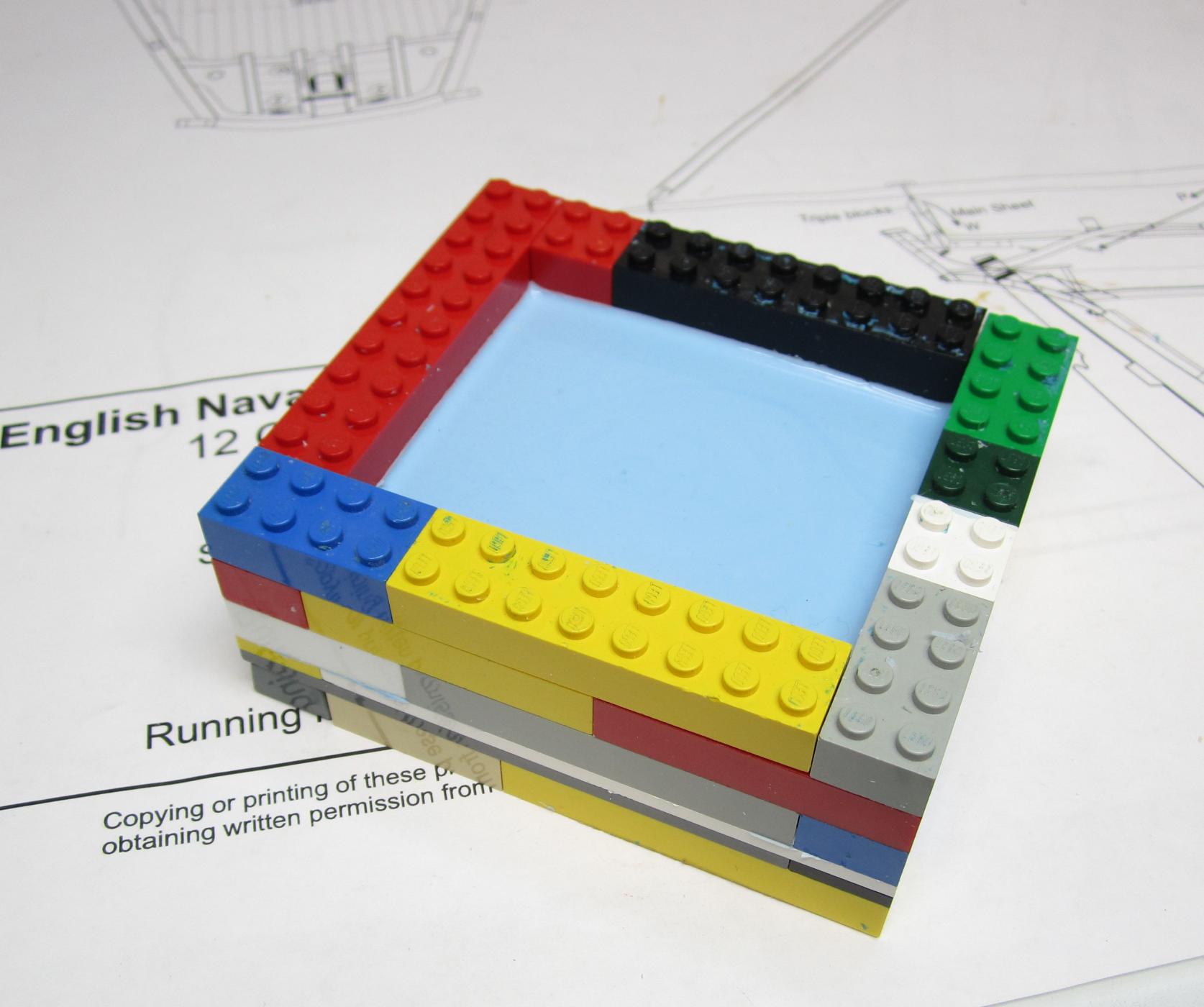
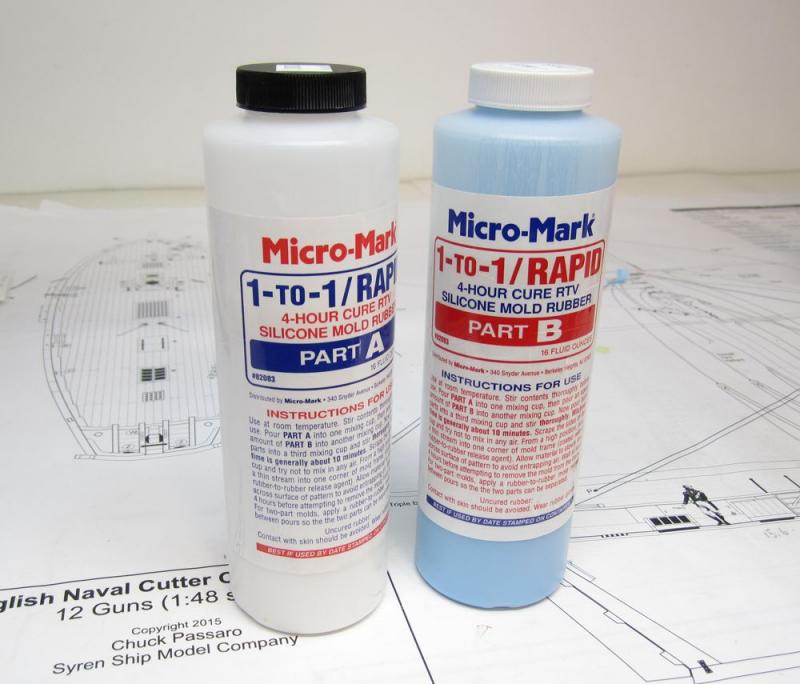
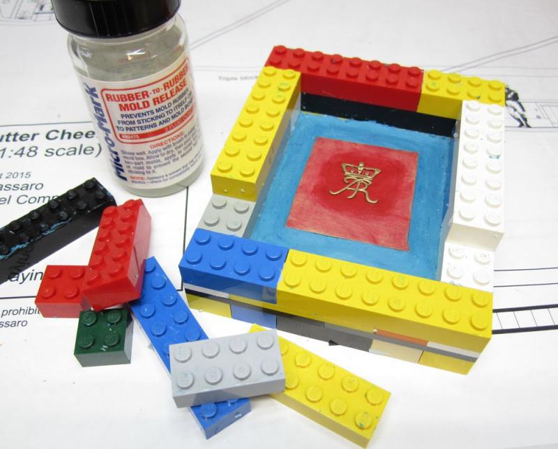
THE MOLD BOX There are many ways to make a mold box. Some folks even use disposable plastic containers. Some make them out of wood. I prefer to use toy build blocks...LEGOS. This gives me more flexibility and I can reuse them to make any size mold box. Because you can remove the blocks one at a time after your mold cures it also makes removal of your mold easier in my opinion. CLAY ON THE BOTTOM In the photo below you can see the master already in position. Surrounding it is blue clay. This is the type of clay that never hardens. It stays soft and pliable. The clay is important for making both simple one piece molds like we are making and two or three piece molds which are more complicated. The clay is usually sold where you can buy the casting supplies. In this case it was from Micro Mark. PREPARING THE MASTER Some tutorials will instruct you to place the master in the clay directly. You would push the clay all around the part so no rubber from your pour will seep under it. This is OK for larger really simple parts....BUT In our case, the tiny intricate pieces (often made from thin fragile boxwood) would certainly break. If your clay isnt perfectly flat it would be problematic as well. That makes it more susceptible to breakage. If it doesnt break it will certainly flex and your mold will produce distorted castings. So I recommend that you adhere the piece to a flat section of wood. In this case a small piece of cherry painted red. Normally it wouldnt be painted but it wont have any effect on the mold making process because its acrylic paint. This gives you a great flat surface all around the master. As you can see in the photo above, the master is leveled in the clay and the clay is smoothed out all around it so no mold material will seep under it when you pour. Note that the master is also painted....not recommended but I really didnt want to carve another one....it did work out just fine in the end. It is also really important that you do your best to ensure the master is level in the mold box. You dont want it sloped one way or the other. This is important when you start pouring resin into the mold as you want the resin to flow properly into the mold. Remember that this is for simple pieces with a flat surface....once they master gets more complex you should think about the best orientation for the piece based on how the resin will sit in the finished mold. Hope that makes sense. BEFORE YOU POUR YOUR MOLD... The master and every surface of the mold box needs to be treated with a mold release. This is also readily available where you buy the casting materials. I am using what came from MM. It is shown in the photo above as well. Brush it onto all surfaces...but dont let it pool up anywhere. Just give the inside walls, the master and even the clay a light coating. It makes it much easier to remove the mold after it cures. This step is crucial when you make more complex two and three part molds. Some places recommend a spray on mold release but this is fine and you have more control brushing it on. Remember no puddles. MIX YOUR MOLD MATERIAL In my case I am using rubber mold material from MM. There are many varieties. Some are extra strength for longevity...tear resistant for masters with complex undercuts and small details...or heat resistant for making metal castings...the explanations are usually very clear on reputable supplier websites. In this case its just ordinary basic rubber mold material for resin casting. Unless you need to make hundreds of parts this is just fine. I have used the extra strength stuff though at times and it works well when you have to make 100 plus castings with small intricate features where the mold might tear. Most of the mold compounds available to you these days will be a two part 1 to 1 mixture. It is important that you stir the contents of both parts A and B before use and before you mix them together. Also make sure they are at room temperature. Too cold or too hot and it will affect the strength and longevity of the mold. It will also take longer to cure. I pour equal parts of A and B into separate plastic cups. They are clear plastic cups so you can see the level of material in each. You can see in the photo that one part is white and the other is blue. This is done on purpose so when you mix the two and stir it you can tell when they are thoroughly mixed. Pour them together in one plastic cup and stir (or fold) together. Try not to agitate it so bubbles form in the mixture. Easy and gentle stirring or folding. Once you see no streaks in the two colors and a uniform light blue color is achieved you are ready to pour. Most good compounds these day are self gassing. Meaning the trapped bubbles will dissipate after a few seconds. But if you were careful it wont be an issue. POURING THE MOLD When pouring the material into your mold box do it slowly at first. Either pour it into the lowest spot of the mold box or in our case, one of the corners of the mold box. Never pour directly on top of the master because you will trap air bubbles around certain areas and end up with a bad mold. Better to start in a corner of the mold box and let the material slowly FLOW around and over the master to ensure no air is trapped. This mold will usually take 5 hours to cure. BUT I always let it cure overnight. At room temperature !!!To de-mold...simply remove the lego blocks and carefully pull the mold away from your master. Try not to break the master if it is intricate. This is also why I prefer to mount the master on a sheet of wood because if it was directly on the clay it is more prone to breakage. STORING YOUR MOLDS Your molds wont last forever but one trick is to place them in a plastic zip-lock baggie and place them in your freezer. Otherwise they get dried out and weak over time....and it doesnt take long for it to happen. Just make sure the molds are room temperature or even warmed up before you use them again. The mold making parts A and B also have a very short shelf life. This can also be extended by storing them in a cold place. But anything of good quality will have a use-by date on it. The worst thing you can do is try to use old stuff you have laying around to make a mold.....it will be impossible to remove from your master and mold box if it doesnt set up and cure. Trust I have been there.....its a gooey, bloody mess. So better to get fresh stuff and use it sooner rather than later. Buy only what you need although its tough to buy less than 16 oz. containers. You can see the finished mold above ready to make some cast copies in resin....that next installment will come very soon. Hopefully I covered everything. Any questions????


- 18 replies
-
- 14
-
-
deck planking shift
Chuck replied to Kurt Johnson's topic in Building, Framing, Planking and plating a ships hull and deck
You are correct....best not to show seams between hatches or fittings. They werent needed as one length would do teh trick and be much stronger. -
Common blocks & the like for 1:64 scale ships
Chuck replied to FlounderFillet5's topic in Masting, rigging and sails
The list of blocks and sizes are correct for syren....you can use the materials list. But yes, when you see a 3/32" block called for, that is the correct size. The problem is that what the kit gives you for a 3/32" block is closer to a 1/8" block. So its not the list that is incorrect but the product that is supplied. You will be safe making the block sizes called for in the materials list. Chuck -
I will be doing a demo at my local club as a follow up to the carving exercise we had. I will also create a photo essay of sorts here on MSW. I have already created the test mold for the live demo and made a few test copies....but will be making more molds of other elements. I will demonstrate one method for making simple one part molds for these flat carvings as it is something that comes in handy for ship modeling. Especially for things like gunport wreaths etc. So look for the demo to commence in about a week. I am just waiting on newer resin and rubber mold material to arrive in the mail. It has a short shelf life. Using old rubber mold materials is also not good because it could ruin your master. I will be trying a few brands so I can talk about and review each of them. I hope you will find this a useful addendum to the carving section as it is somewhat related. I hope its OK with you folks that I post here in this area. Below is the first mold....a master carving....and two cast copies. Casting thin parts is problematic but its what we do as ship modelers so lets give it a go. Chuck
- 18 replies
-
- 27
-
-
The main stay isnt situated on top of the shroud gang....just slide it over and around the back of the shroud gang...This is actually more stable and typical. Take a look at this contemporary model... although it is not a cutter, it is still typical of how the stay appears around the shroud gang rather than stacked "next in line" on top very neat. If that makes sense. It need not be stacked. Although mine did seem to fall that way naturally.

- 452 replies
-
- 17
-
-
- cheerful
- Syren Ship Model Company
- (and 1 more)