HOLIDAY DONATION DRIVE - SUPPORT MSW - DO YOUR PART TO KEEP THIS GREAT FORUM GOING! (Only 27 donations so far out of 49,000 members - C'mon guys!)
×


Chuck
-
Posts
9,660 -
Joined
-
Last visited
Content Type
Profiles
Forums
Gallery
Events
Everything posted by Chuck
-

question about waxing thread
Chuck replied to ford34tom@comcast.net's topic in Masting, rigging and sails
I dont use wax ever. My rope doesnt need it at all. It just obscures the detail of the rope and attracts dust which sticks to it like a magnet. Unless your rope is a fuzzy mess. Dont use it. Instead, run your rope through a alcohol flame rather than a candle flame because it wont leave soot. That gets rid of the fuzzies. But never wax. Best thing to do is buy better rope. No stretching, wetting or waxing needed. Just use it out of the package. Rope of Scale or Syren makes perfect rope. You just have to pick the one that you like better because the color tan and brown is slightly different from both sources. Chuck
-
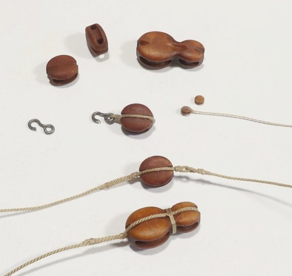
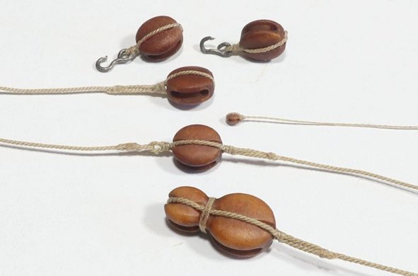
Thanks guys for saying. I am quite happy with the finish and color. And not just the darker Swiss Pear color blocks. The Boxwood 3D printed blocks are just as good and this is a much harder color and texture to pull off. I dont know of any other source for 3D printed blocks of this color . Here you can see the difference in the two colors. Chuck

-
After a weekend of busy sales...rest assured I should be restocked with blocks by tomorrow afternoon....You guys must be building a lot of ship models. Actually finishing up more 2mm single blocks as I write this. Then onto rope.
-
Lovely work Chris.
-
Oh my!!! That was sure some kind of machine, LOL. The plans are still out there if you can get parts. Google it!!!
-
You could easily use the Model Shipways ropewalk. Its flimsy and pricey for what you get but at $50 it will do the trick for just your own model. My more robust version of a ropewalk will hopefully be back soon and it is also easy to make your own. I used the MS ropewalk for years before I went into the rope making business. Chuck
-
As it seems many of you noticed, I opened the store yesterday around 3pm. Its all going quick...at this pace in another day or two it will be all gone again. I am very thankful as always. But I wont shut the store down again. Whenever I get around to restocking the items I will get around to it. Its just too much....so it will get done eventually. Sorry in advance for the wait times. Its gonna be a slog. Chuck
-
Actually my head stock and tail stock are 43 feet apart when I make my 30 foot lengths of rope. You were pretty close. LOL
-
Ok let me get this other group going for the capstan first and once I get caught up and running smooth with store again. Chuck
-
Yours would be just as good really. Its kind of hard to make bad rope actually once you get the feel for it. I think I mentioned this once before, we had a blackout a few years back and I was still able to make rope in complete darkness by feel. Once you learn it is absolutely like riding a bike. I think it took me slightly longer, LOL....maybe 8 minutes per package rather than 7, LOL.
-
Not at all. You dont have to make 30 foot lengths. You could easily make a 12 foot length on demand when you need it in about 10 minutes or less. Is it a luxury to have more space to make longer lengths....absolutely. But the beauty of some rope walks is the ability to make ropes of any length or thickness on demand. When I was making rope for just myself, I made 12 foot lengths. When I opened the store I started making 20 ft lengths and then increased that again to 30 ft for the same price to give folks more product for the same $$. So it was very economical for people to buy way more than they actually needed. But making it on your own, your costs will only be for the ropewalk and for the materials. The material cost is ridiculously low. Its the labor costs you guys are paying for. You can buy one spool of Guttermann Mara thread for $4.50 From that one spool of thread you can make 15 packages of .025 tan rope 30 feet long. Its all just the labor costs. So it is well worth giving it a try and even making shorter lengths. Chuck
-
Glenn, I dont think so. In this particular case, I think there was just an unfounded rumor floating around that I was retiring and shutting down the shop. That is far from the truth. I will repeat that I am going to be around for a whole bunch more years. Only two things will make me shut down earlier , I drop dead, or I hit the numbers. So there is no need for hoarding and I think folks will realize that when they see things stay the same once I reopen. But I will revamp my effort to teach and encourage folks to make rope on their own. I will make more video tutorials and even maybe a workshop or group project of some sort. I might possibly release my plans and files for my ropewalk and we could have a group build. You could make it without a laser cutter. I could work up a material list and the sources to buy the stuff needed. Would you guys be interested in that? Glenn I am curious...have you ever tried making your own? You would be good at it. You get to pick your own material and the color and even the infinite number of sizes you would be able to make. More than any store could sell. And make rope on demand the moment you need it. Chuck
-
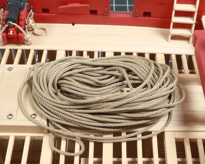
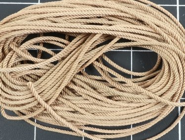
That is an option but for now I am good. I will just do my best and if folks have to wait a little bit for me to restock once in a while then hopefully it will be worth the wait. I used to have help with rope making but my son in law has moved on to other things. Ropewalks may be back in stock soon as well so hopefully more folks will try and make their own. They really should try it. Making rope for just one project you are working on, at the moment when you need it is just too easy...it takes less time than waiting for the mailman to deliver the stuff you buy from me or anyone else. This 30 foot length of rope literally took me 7 minutes to make and its perfect. Its only when you have to make 2500 feet of rope per day...every day... that it makes you want to stick a fork in your eye. Chuck

-
Thank God!!! I am on my last size of rope for restocking... Shouldnt be long now.
-
Lovely....so elegant!!!
-
People are sending me requests to join the group. Dont do this. This is just a quirk of the software. This is the way it will work. Once I finish setting up the tutorial topics. I will announce it is ready for folks to join. The NRG will add a store item to its online shop. You will have to go there and buy your access to the group for five bucks. We are still setting that up. Mary will contact me with your information and I will send you an invitation. You will see your the invation and will be able to click a link to accept it and join. Basically its the same way it works for the Winchelsea group build. Thats when you will gain access to download the files. If you are not 3d printing or laser cutting your parts, its free to join as you will be able to buy a kit and start a build log without paying $5. You only have to pay the five bucks for access to the files if you are making the parts yourself. Chuck
-
Yes that is so true. I never charged enough and I give too much away for free. And I work way too much. Life is too short. I hear that from her every day lately. LOL... I guess this is a good post to give an update on the capstan project. Another brilliant business decision. I have completed the build log and added all of the files for download. I just have to write a few topics of instruction for the materials I am using and the techniques I used...all of my secrets and methods. Then folks will be able to join this project area and download those files and make their own kit. If you dont have a laser cutter or 3D printer, thats OK too. J.J. (scrubbyjoe) has agreed to produce these kits for sale so folks can buy one and join the group to start a build log alongside the others. That is free and you could a tually start a topic in that area right now if tou wanted to. I dont suspect we will have a lot of people who will be laser cutting their own stuff or 3D printing their own stuff yet. But I do think that this number will increase in the future. And yes I am giving this project away for free and J.J. has my permission to produce these and sell them. If anyone else wants to, they must get my permission first or you can just use the material for your own personal use. This is all new territory and we are testing out a new way to bring projects to our members. Having said this, We will be charging a small fee to join this club area for the downloads only. Not so MSW can make a killing off it, but so we can keep track of those with access and manage the release of the files out to the world. The cost to gain access and be invited to download these files is just $5. Just five bucks, LOL. So yes, please dont tell my wife that I am giving away something else, LOL I will never make the Forbes 500, LOL But everyone have fun. Chuck
-
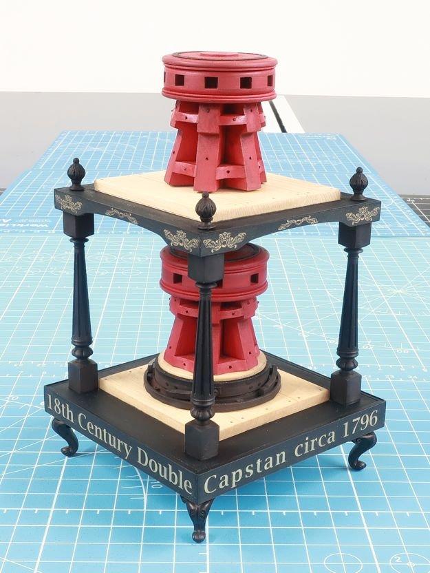
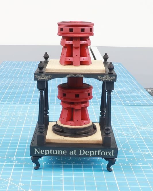
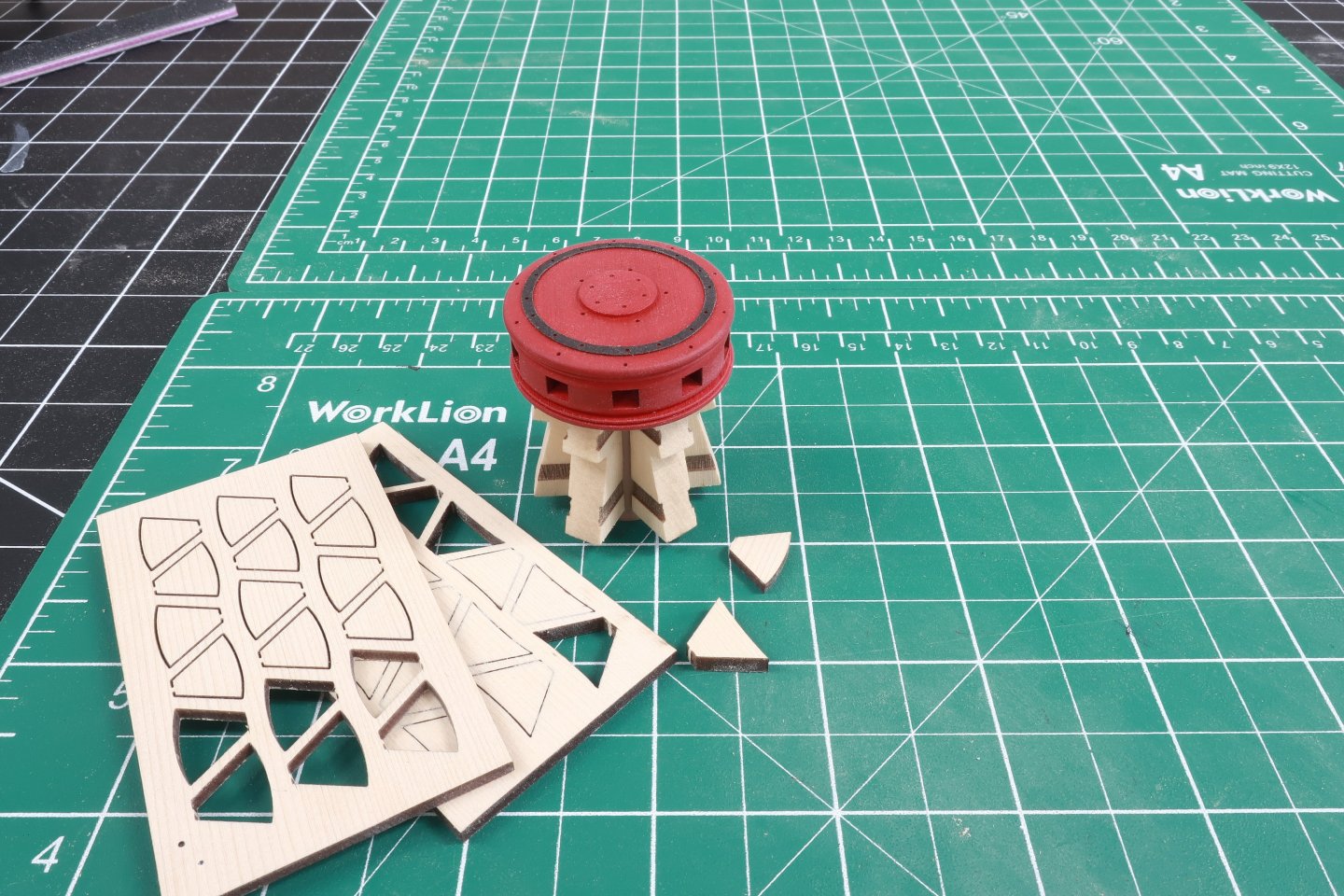
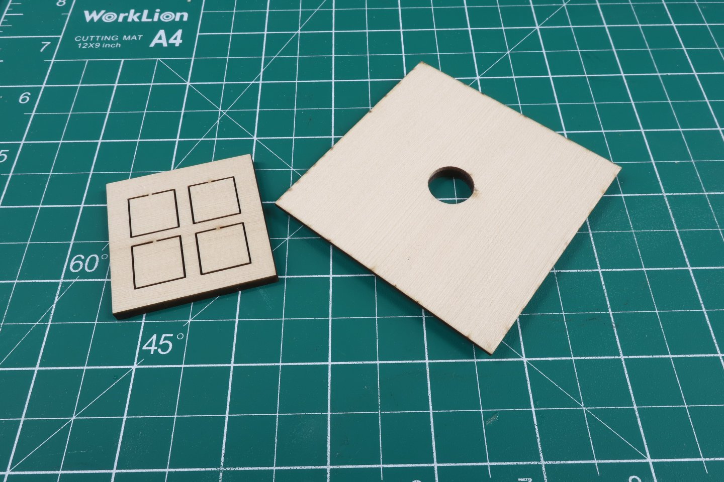
You should add the chocks just like you did for the lower capstan. They are the same sizes and from the same laser cut sheet. From this point its all the same. Paint the capstan red and add the bolts on the whelps and chocks. Not to rush this in the instructions but it is literally the same as you did for the lower capstan. That finishes it all up. With a tiny stick glued into the center square hole on the bottom, sit the upper capstan in position. The square stick should easily slide into the square hole on the lower capstan. Hopefully the two center shaft parts actually meet and touch each other so you can glue it into position permanently. But if you need to use an optional spacer...this is the time to try it. You dont want the upper capstan marking up the upper capstan partners when it rotates. If the upper capstan is too high however and there is too much space between the bottom of the whelps and the partners, sand down the center shaft until it fits better. I hope that makes sense. This leaves only one more step before you complete the model. You can add the four 3D printed finials to the corners. Just sand the bottom of these flat so they sit nicely on the surface. Make sure you glue them directly over the columns so they look like they are supposed to look. They should look like an extension of the those four columns. Thant completes your model. Note how the chocks are positioned differently on the upper and lower capstan. This is pretty typical and an interesting detail. Also note how for these later capstan designs there are no pawls onthe upper deck at all. Again very typical and why I chose this later design as the subject of this project.

- 23 replies
-
- 10
-

-
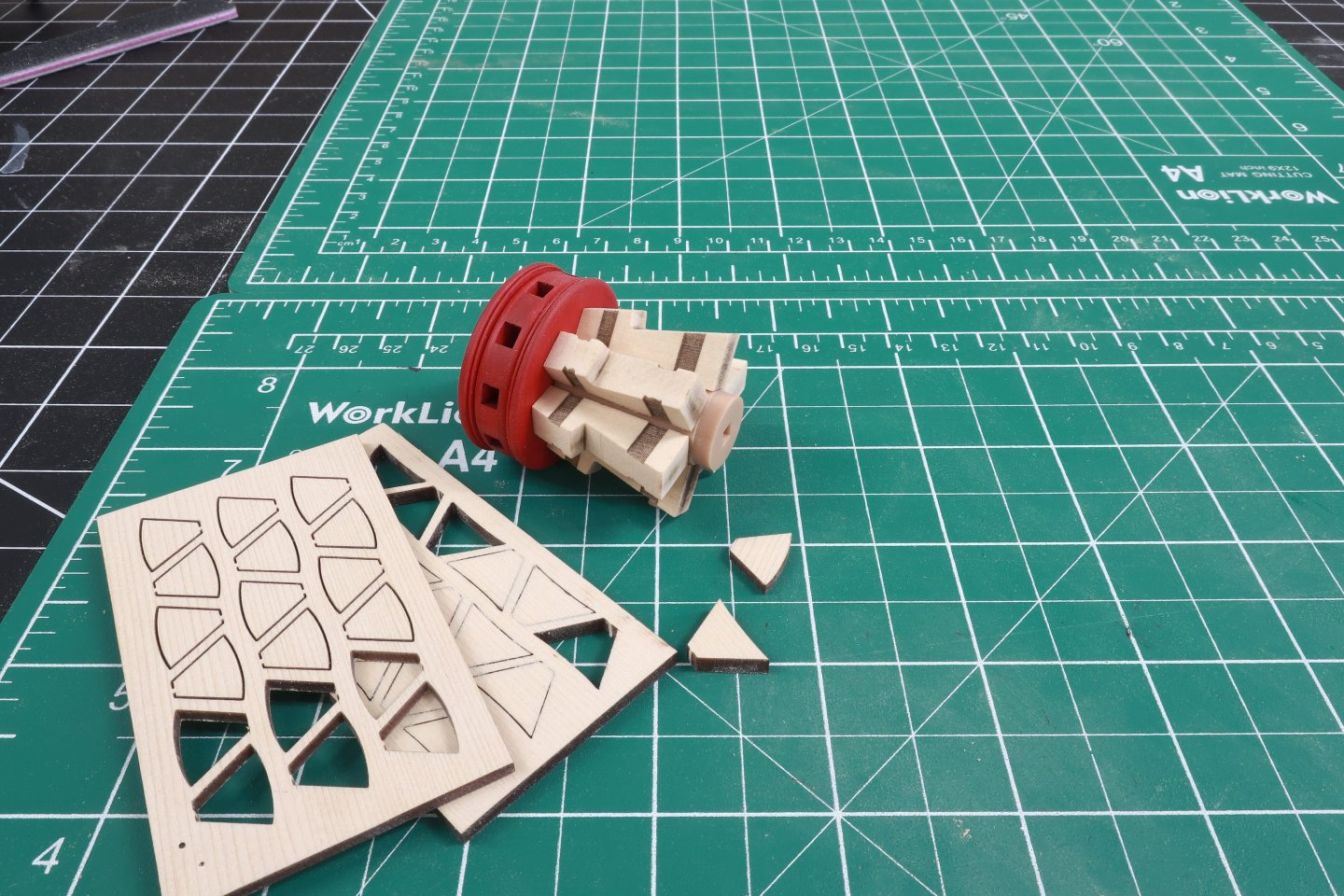
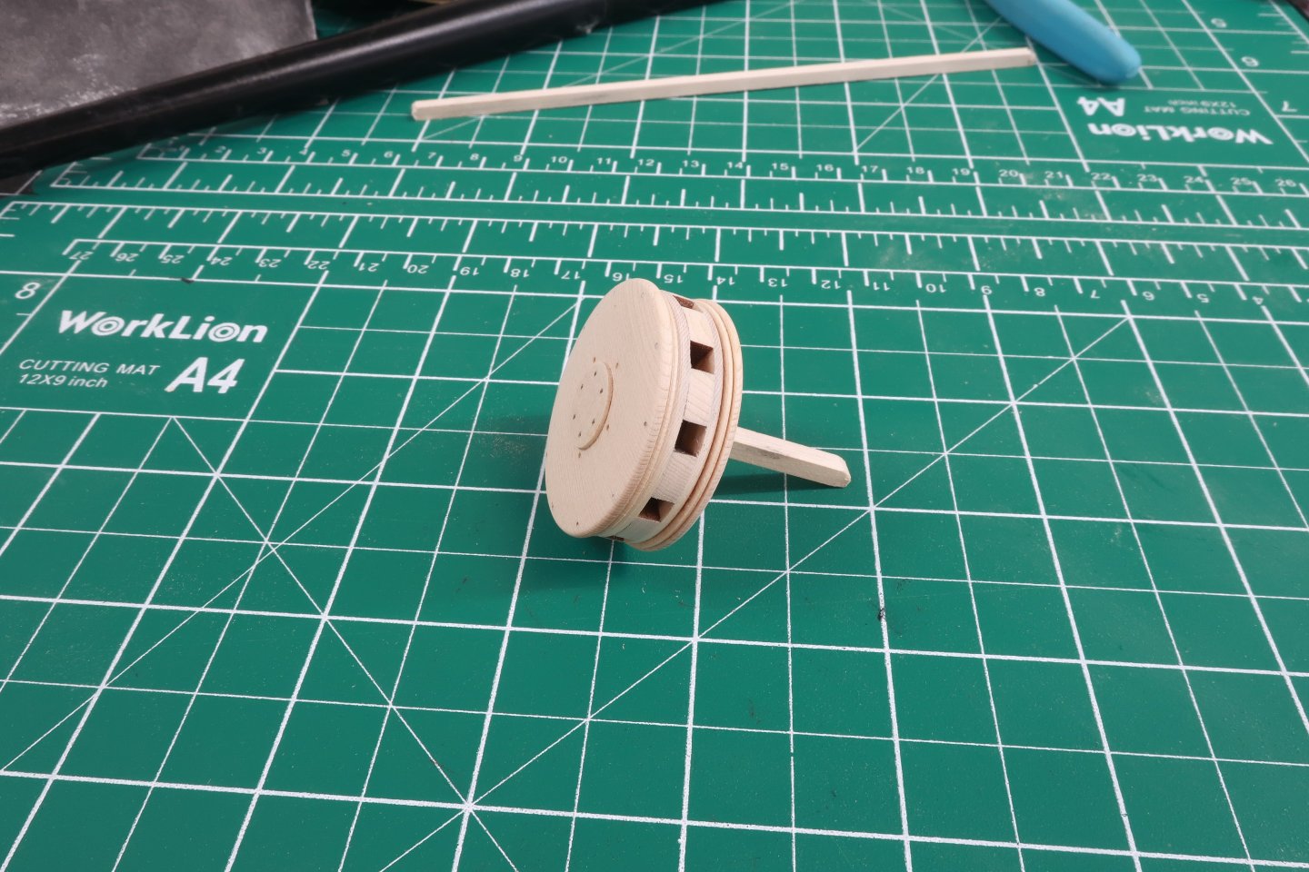
OK, the center stick you have pushed into the hole on the bottom of the capstan drum can be glued in there permanently. It doesnt have to be very long at all. Maybe even just 3/16 - 1/4" long. It just has to be long enough that you can glue the last 3d printed center column section onto it. The circular end is the bottom. Glue that onto the stick. Make sure the ends are sanded flat before you do so to prevent any gaps all around when the two pieces are pushed together. You can see below that after the whelps for the upper capstan are sanded free of char and glued onto the center shaft, the round portion of that shaft is visible. This will be slid into the hole in the center of the upper capstan partner. Test it in position. Note where the bottom of the whelps fall in relation to that circular part of the shaft. Once you have the whelps all sanded and glued onto the shaft, test its fit on the partners. There should be just a little bit of space between the bottom of the whelps and capstan partners. It should sit right on the capstan partners. It shouldnt be touching it. It should be just a hair off the surface. Now when it comes time to place the finished upper capstan on the model, you will push another 1/8" stick into the hole on the bottom of the capstan. Then this is pushed into the cenetr hole of the lower capstan making a nice solid connection. But maybe for whatever reason, you will need to raise your upper capstan a bit more so it doesnt rub against the upper capstan partner. There are laser cut optional spacers you can add between the upper and lower capstan so you can adjust its height if you need to. But I get ahead of myself here. We still have to add all the chocks between the whelps for the upper capstan. Yes I also painted the upper capstan drum to get ahead of the painting and also added the laser cut iron ring which is made from black laserboard.
-
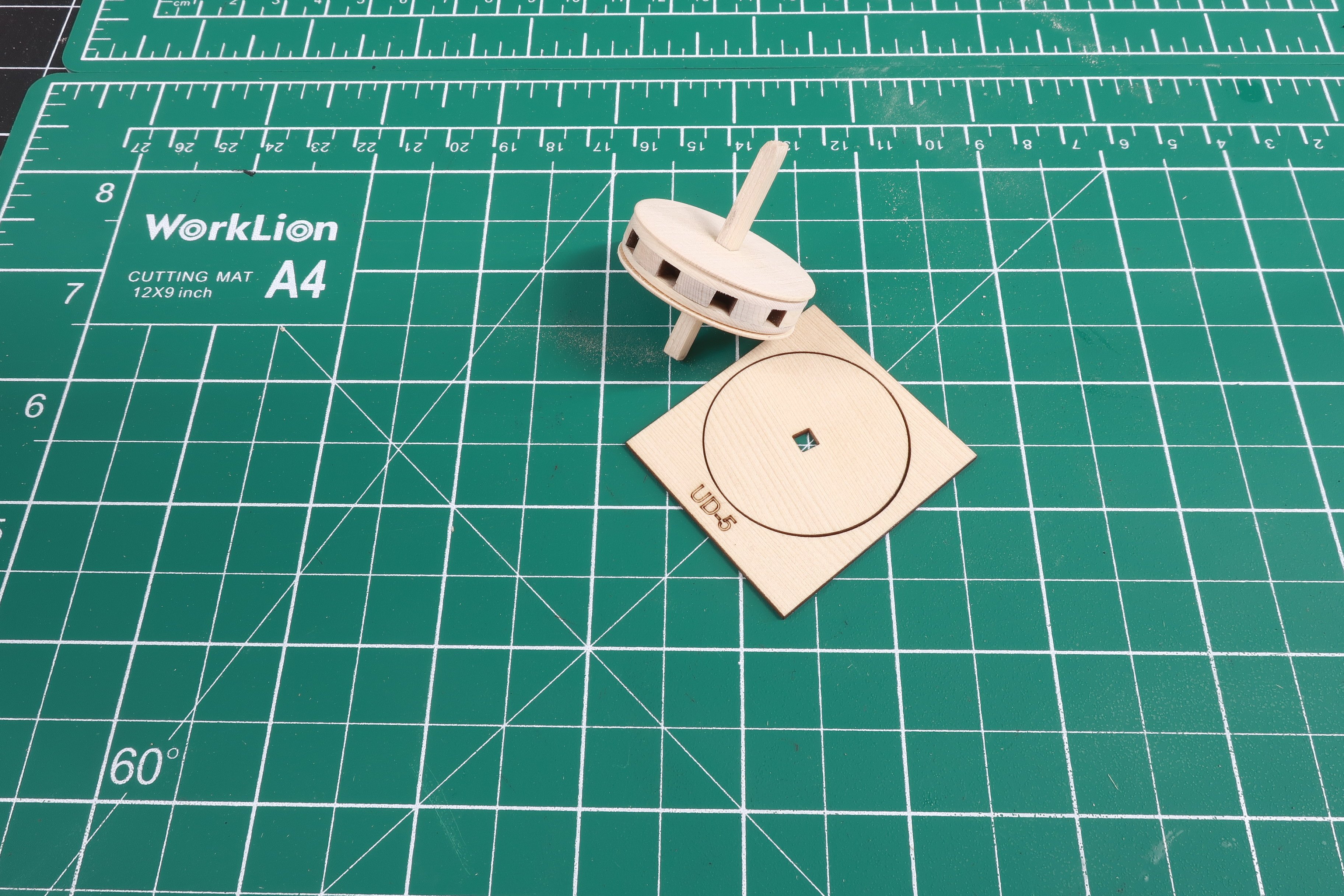
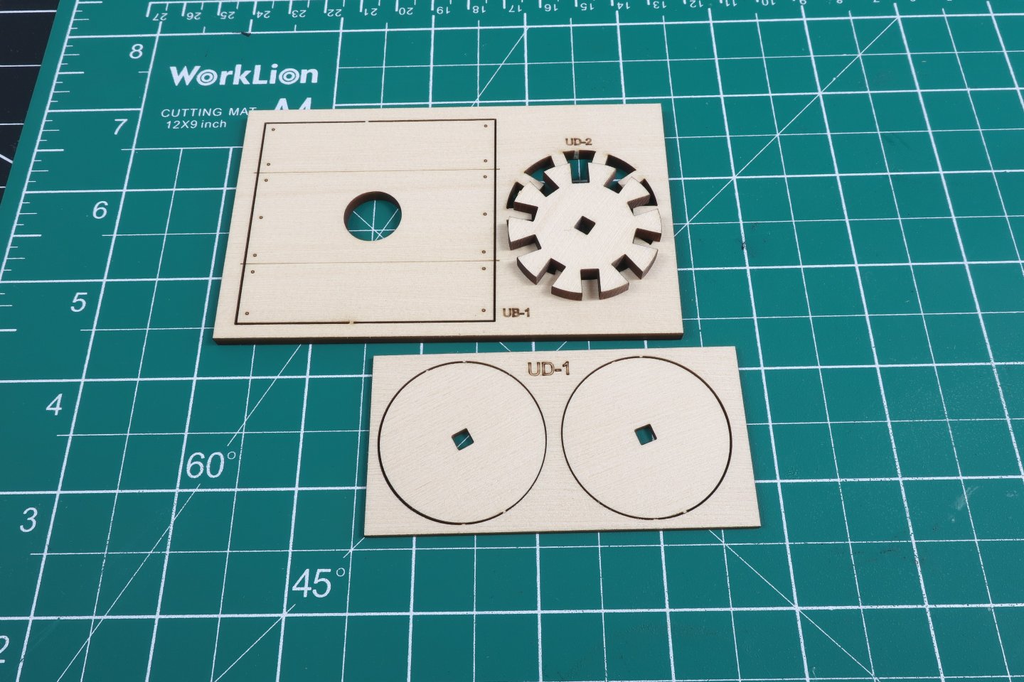
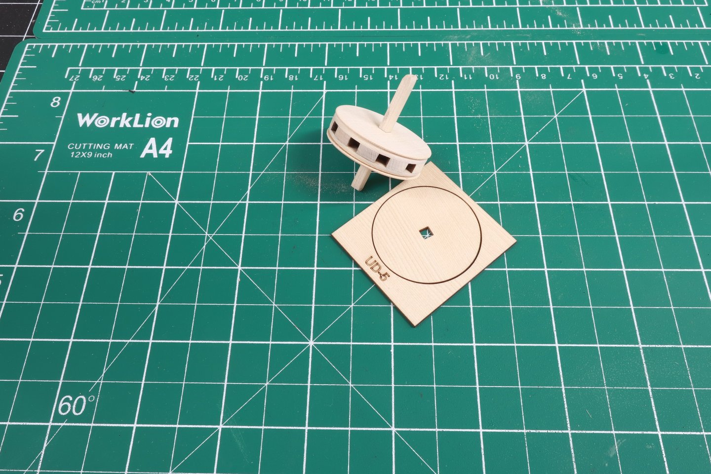
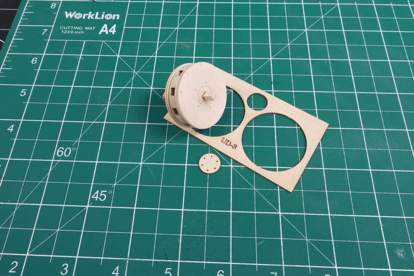
Ok I am going to run through the building of the upper capstan quickly. Its basically a repeat of the lower capstan assembly. Take the center sandwich of the upper capstan drum along with the two slices of bread (UD-1) You know the drill. glue them together and slide them onto the 1/8" stick. Chock it up and sand the sides to shape as you did with the lower drum. Then add the next two layers (UD-3) and sand them in the drill...so far so good. See below. Then add UD-5 which will be the bottom of the drum. The photo above shows it at the ready. To finish up the main work on the upper drum, Use the thicker UD-4 which will be the top of the drum. But dont forget to line up the holes for the capstan bar pins with the notches in the drum for the capstan bars!!! Chock it in the drill and sand away. Shape it like the lower capstan drum making the profile thinner along the outside edge. Dont sand away that laser etched circle in the center of the drum head. You will be gluing a tiny circle just 1/64" thick there. It also has holes to simulate bolts. You could technically add some black fishing line in these holes and cut them to simulate the bolts later. But for now, just remove the 1/8" stick and glue that little center circle in position. It should look like this. I put that stick back into the hole from the bottom of the drum and gave the whole assembly a sanding in the hand drill. I used some fine grit sandpaper to give it all a nice finish. I even sanded the top of that center circle so it was even thinner. But that is just a matter of personal taste.
-
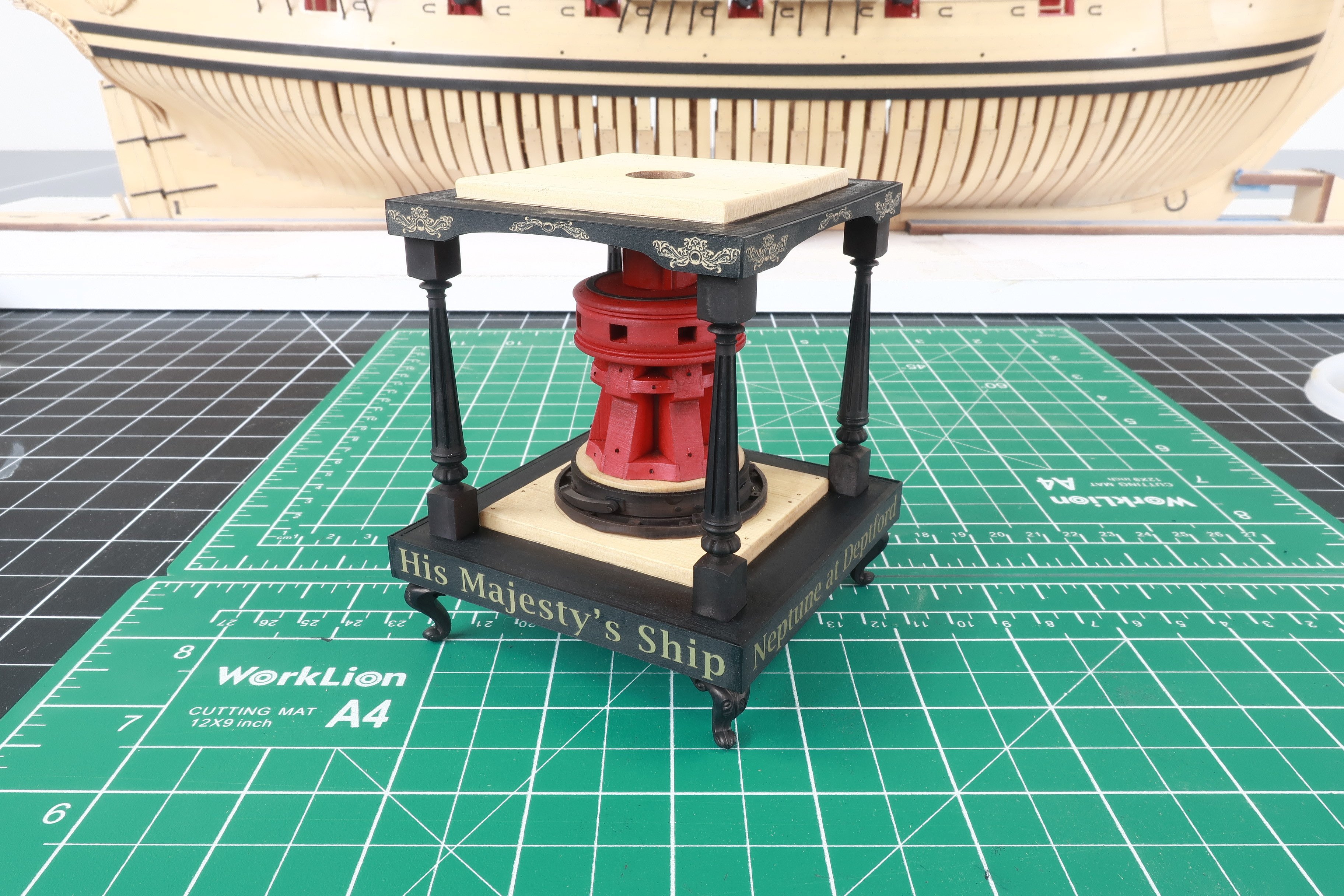
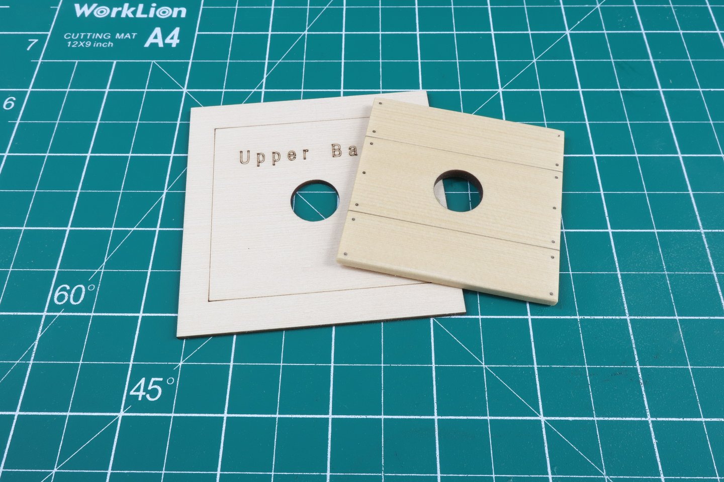
Paint the top of the platform around the partners black. Then adhere the fancy etched gold and black sides. Do this exactly the same way that yo did on the bottom base. Do two opposite sides first. The top of these side pieces are flush with the top of the upper base. Carefully trim back the ends and then apply the remaining two sides. Repeat.... They are self adhesive. They will stick really well to the sides of those little squares on each corner and the sides of the upper base. Now its time to test the upper platform on your capstan with the four 3D printed columns glued onto the lower base. Try and keep those columns vertical as you glue the top platform onto the columns. I placed some glue on the top of each column and while it was setting I adjusting the angles of the columns by eye until I was satisfied. You can of course use more precise methods. I just eyeballed it. I made sure the top of each column looked to be in the same place in relation to the corner squares under the platform. You may find it easier to flip the model upside down also. The center drum of the capstan should slip into the center hole of the platform. It should not be too tight as you want it to spin...but not too loose either. Just a little play within the center hole. Once the glue dries, rotate that lower capstan to check its movement. Make any needed adjustments so it rotates freely.

-
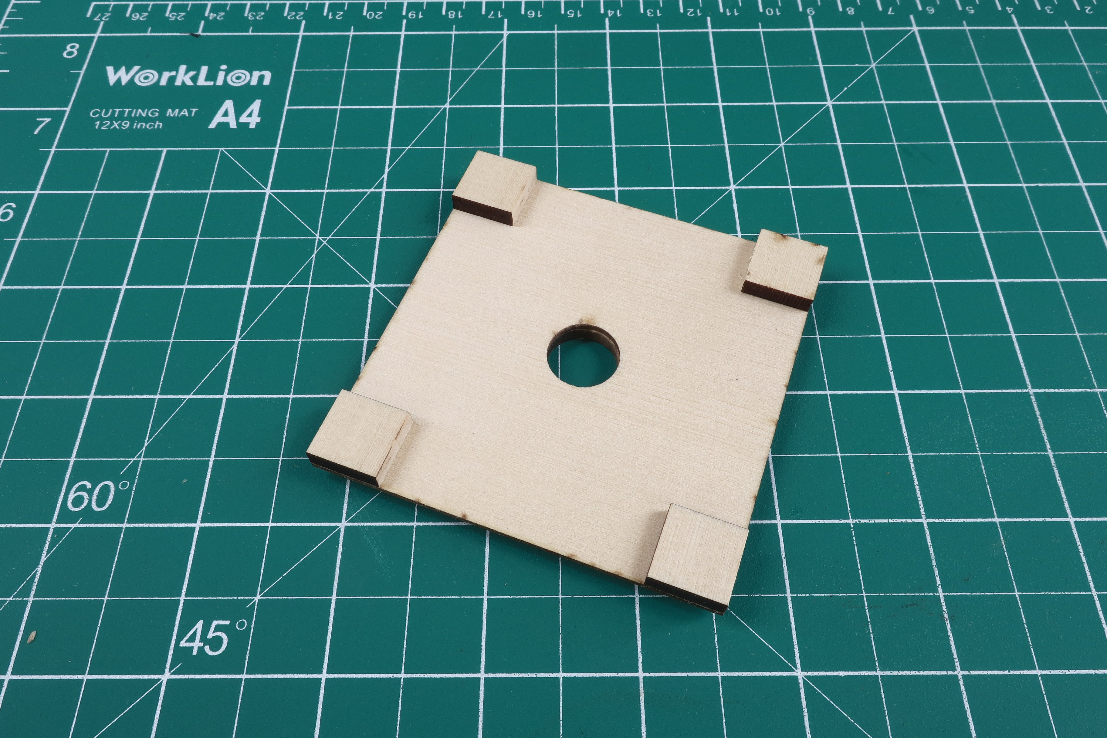
Continue by starting to build the upper platform or deck between the two capstans. Take the laser cut upper base (1/16") and glue the upper capstan partner to it. It will fit between the etched lines . Of course sand the char off the edges of the capstan partners and soften the edges a bit too. Then flip it over so you can glue the small laser cut squares into each corner of the underside. Just glue them in each corner flush to the edges of the upper platform.

-
LOL....I can see me at the ripe old age of 85 making 75-100 packages of rope a day!!! 7 days a week. It has to end at some point. Ben makes a great rope too!!! Or as I have mentioned. Its so easy to make your own and it will cost you pennies. No waiting on the postman either. Give it a try. Its funny actually. I have sold a rope walk to a lot of people (probably 6-700 or more) and I still see those same guys buying my rope instead. I have to scratch my head. It is so easy with a little practice. Its not rope rocket science. And it will be just as good if not better. I think I have to teach more folks to fish. Maybe I will release my rope walk plans/files so folks can make their own or go get them laser cut somewhere...more people should try and make their own. Chuck

-
Thank you.....but dont buy too much...LOL For rope specifically....it isnt Rocket science to make nice rope. Ben makes fantastic rope at ropes of scale as an example. I really wish more of you would try making it yourself. You really dont have to pay someone else for rope as it is so easy to make. It still surprises me how much of it I sell. I sold 30 foot long packages or 9 meters for $5.50 Ben sells the same length of rope for $9.50 US So in order to get more on par with that and others...I now charge $6.75 Still a pretty good discount. For 3D printed blocks, I was charging just $4.50 - $5 for a package of 25. To bring that price in line with others who basically sell the same thing....These will now cost $6. So we shall see how this goes. They other guys are up around $7.50 to $8.75 Maybe at closer to real market pricing the hoarding will ease up a bit. Once I actually did the comparison I realized how low my prices actually were and how it probably contributed to that phenom. Because I really dont want to stop just yet if I dont have to. I think I have a few years left in me churning out rope, blocks and fittings. Chuck
-
Because as I have found out...it really doesnt work. I have had folks just ask their wives or neighbors and friends to order and they brag to me about how they "beat me". So only the honorable folks actually get burned in the end by complying with a reasonable request like that. The guys who dont care are obsessed about getting what they want no matter what. Working retail can be stressful sometimes. I am just going to try and keep up and make more until it hopefully settles down. But let me tell you, it aint fun making rope every day for 8 to ten hours. Sadly there is only one method that truly works....I hate to do it but folks have been telling me for a decade that my prices are too low. I took a long hard look at what other companies charge for this stuff and its crazy. I think my stuff is the best by comparison (I am biased) and I was still 30 to 40% and sometimes 50% cheaper based on the lengths of rope and blocks I offer. So yes when I reopen, my prices will be 50 cents to 75 cents per package more expensive than when I shut down to restock. Not a huge amount but maybe enough of a deterrent against buying 12 packages at a time of everything. Sorry guys...between my costs going up and the hoarding...I have no choice. I am tired. Its either this or I just shut it all down and find a part time job where I am not churning out rope and blocks at a very low margin.... working 70 hours a week, 7 days a week. The admiral might have a point except for the fact that I do love doing my small part in making the hobby more enjoyable for folks. But like me, its getting old fast. Chuck