HOLIDAY DONATION DRIVE - SUPPORT MSW - DO YOUR PART TO KEEP THIS GREAT FORUM GOING! (Only 24 donations so far out of 49,000 members - C'mon guys!)
×


Chuck
-
Posts
9,660 -
Joined
-
Last visited
Content Type
Profiles
Forums
Gallery
Events
Everything posted by Chuck
-
 There are actually more possibilities. There is free software out there that takes a 3d in the round stl file and converts it to a relief. That is the next installment. You see, what happens when you ask AI to make a sculpture from a drawing or photo doesnt always result in a bas relief carving. It will generate a fully in-the-round sculpture. For these you have one additional step. You must take that fully 3d sculpture and convert it to a relief. I wasnt taught any of this. I was just curious and started doing online searches for different techniques. Just search google “3D file to bas relief”. There is so much out there from folks more knowledgeable than me. There are so many Yourube videos. A lot of them show software you must pay for though so be sure to add “Free” in search. Or you can try and get all your sculpture done during the free trials for the software then cancel them. A lot of folks do that but its not really nice as everyone needs to earn a living.
 -
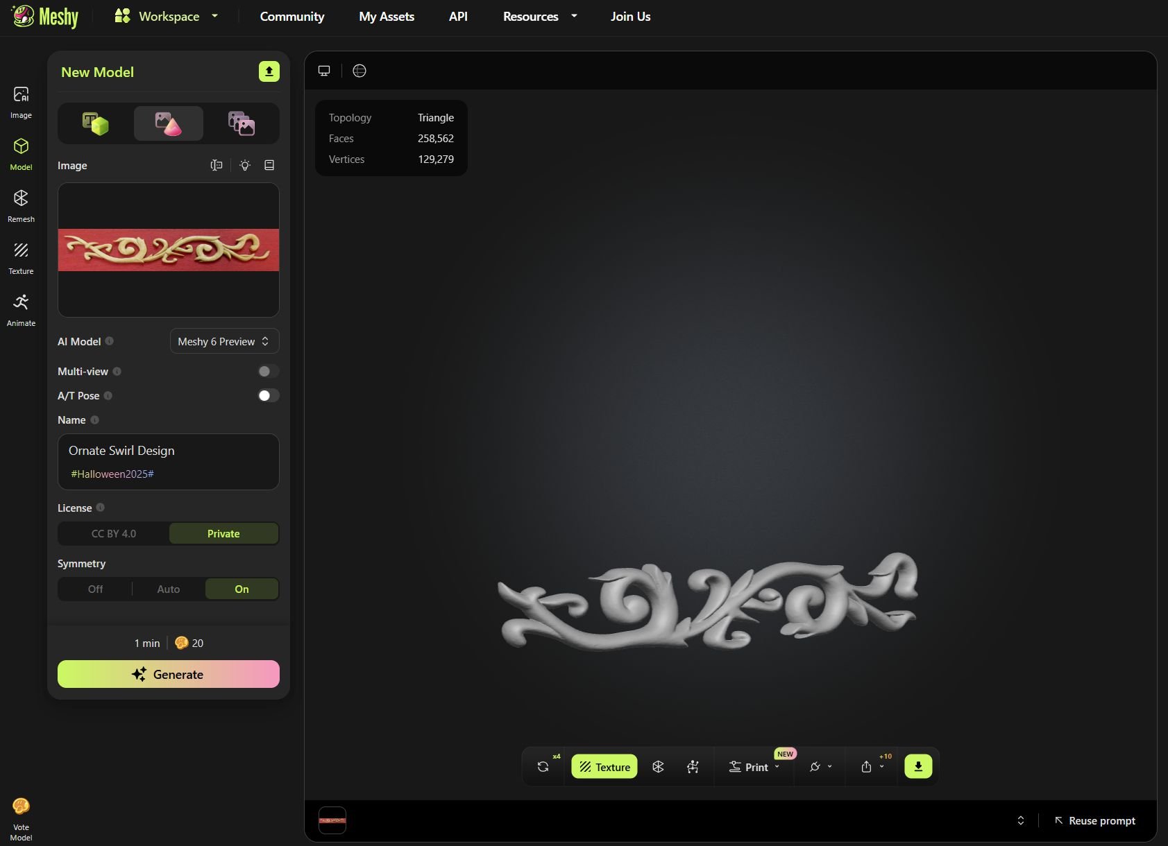
Continuing the conversation...a more complex carving Using drawings...I really hate how easy it has become to steal stuff but it doesnt take a rocket surgeon to figure this stuff out. If you are using it for your own model its fine. It is just another tool. If you use it for commercial purposes then its not cool at all. Here is my drawing, a very bad one done for one of the speedwell transom carvings. It is right from my plans. So if you have decent plans for your model....you are good to go. If you can draw even better. All you need is a good line drawing. Plugging this rather doodle like drawing I made into Meshy. I wanted to show you what a line drawing would turn into. Or from a plan drawing. You get this. I couldnt carve this. You can adjust the relief thickness in other programs as well. If you are curious and ask it to try again....you get another version...can you spot the AI weirdness. I m not saying it is perfect yet. But I couldnt come close to carving this thing. And certainly not in 45 seconds. By the way I paid a CAD guy to create mine and this figure or any one figure like this would cost me $250 to $300 to have done. I feel sorry for those guys in the next few years as the programs get better and better.
-
That is exactly why I am taking the time to add as much info here as possible within reason to help motivate folks. Dont be intimidated. Give it a try. I am always amazed by how few models from a Seawatch book are actually made from scratch. All of the info is there but when people see the carvings they just say...no way. If you want to take the time to embrace the technology you can absolutely build those beautifully designed models. Like the Pegasus for example. Now the downside to this is of course the ease that someone can rip off somebody's work. And yes that will probably happen with increased frequency now. But hopefully I am just being negative and there are more hinest people out there than dishonest. But yes this opens up so many possibilities. The scanners arent needed really. They are getting better and cheaper for larger objects but if you have a small object (ship model parts are tiny) they really dont work well at all. Unless you have an object 10 times the 1/4" scale version you are out of luck with scanners. But photos and drawings work really well now if you are willing to be satisfied with the small peculiar details the AI adds to a model. But give it another six months and it will be even better. The programs are improving that quick. Chuck
-
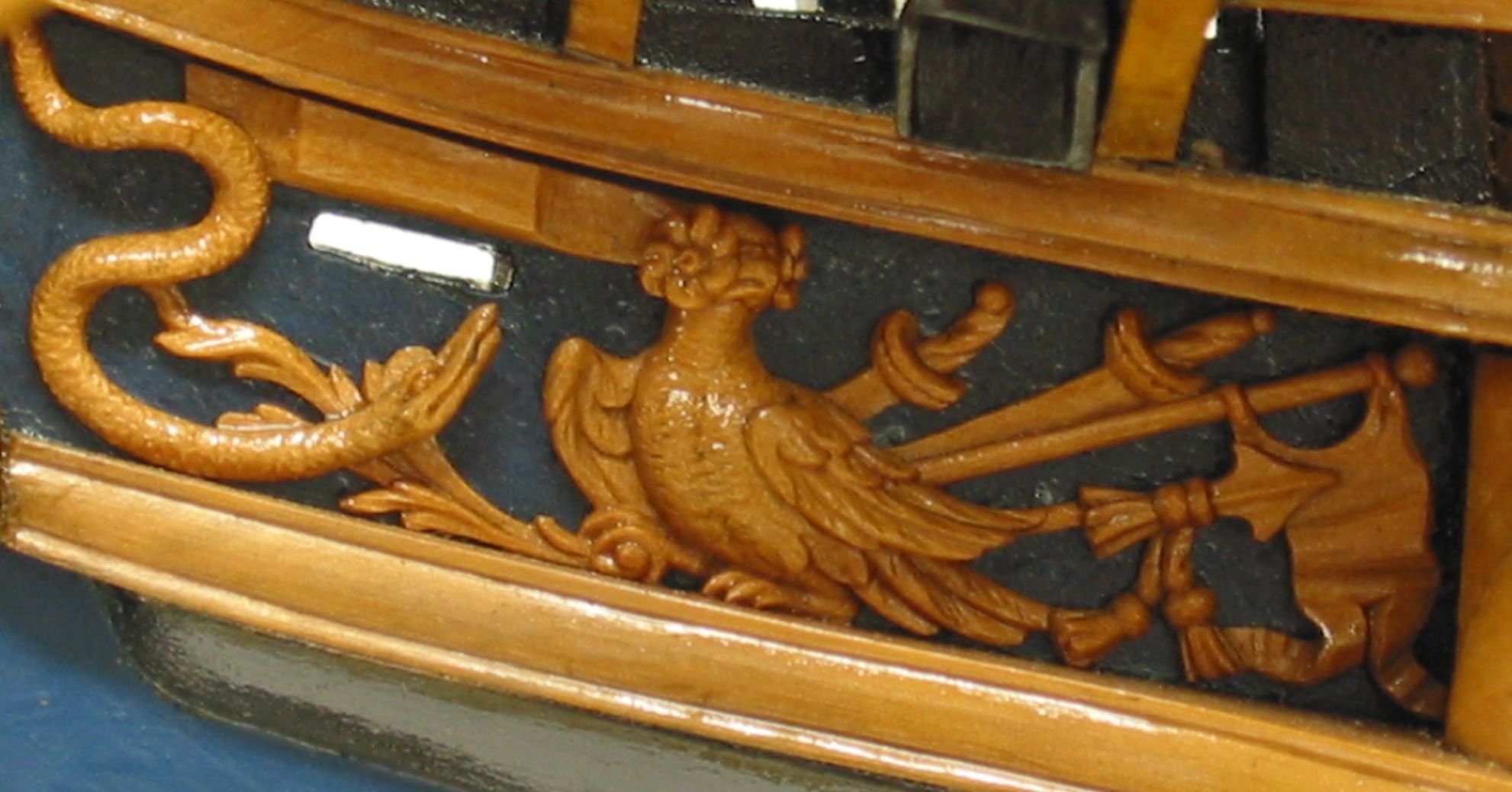
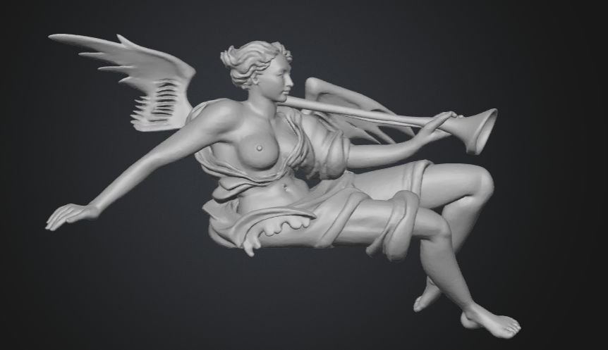
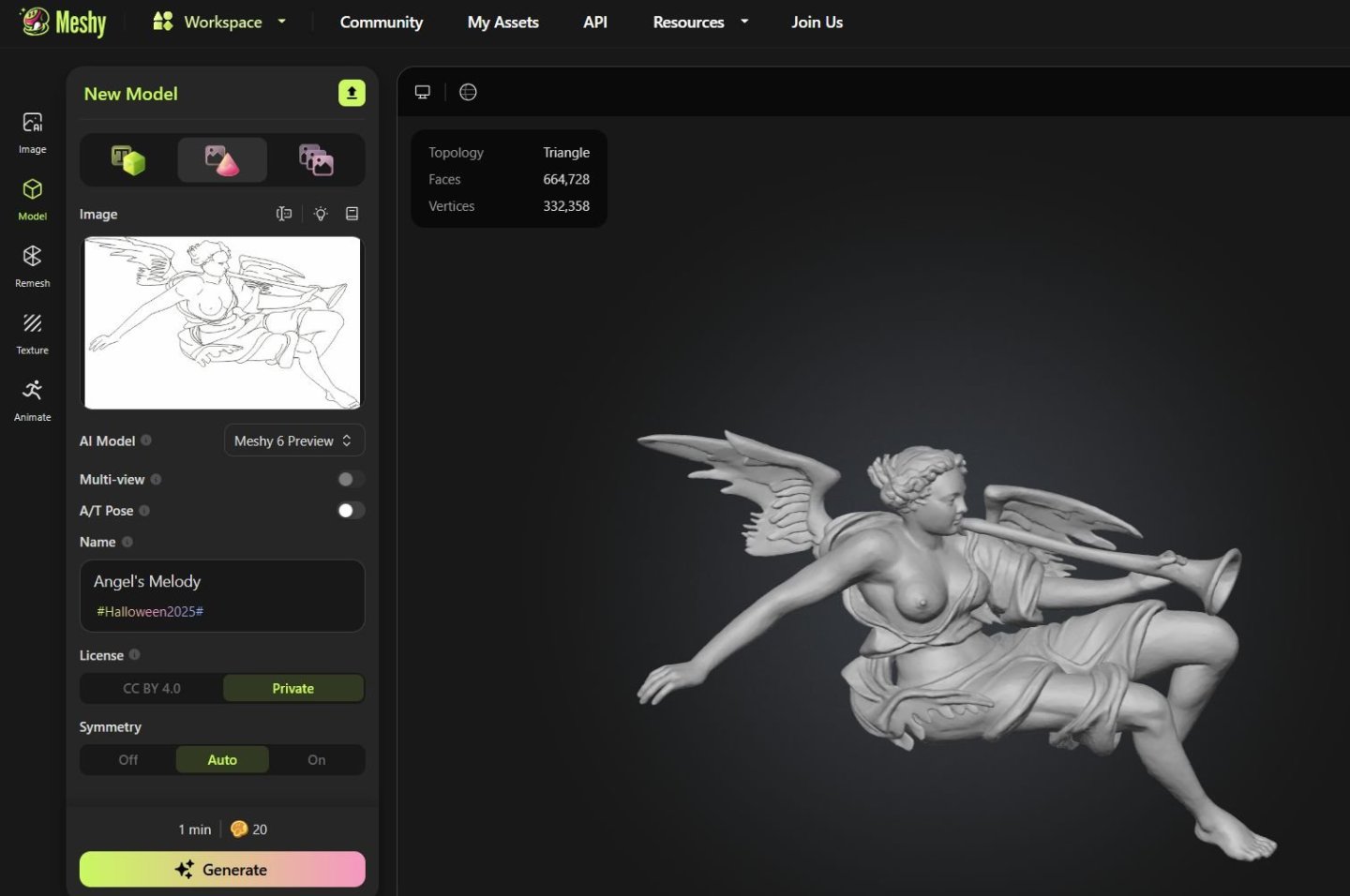
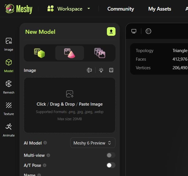
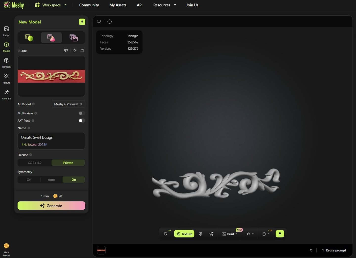
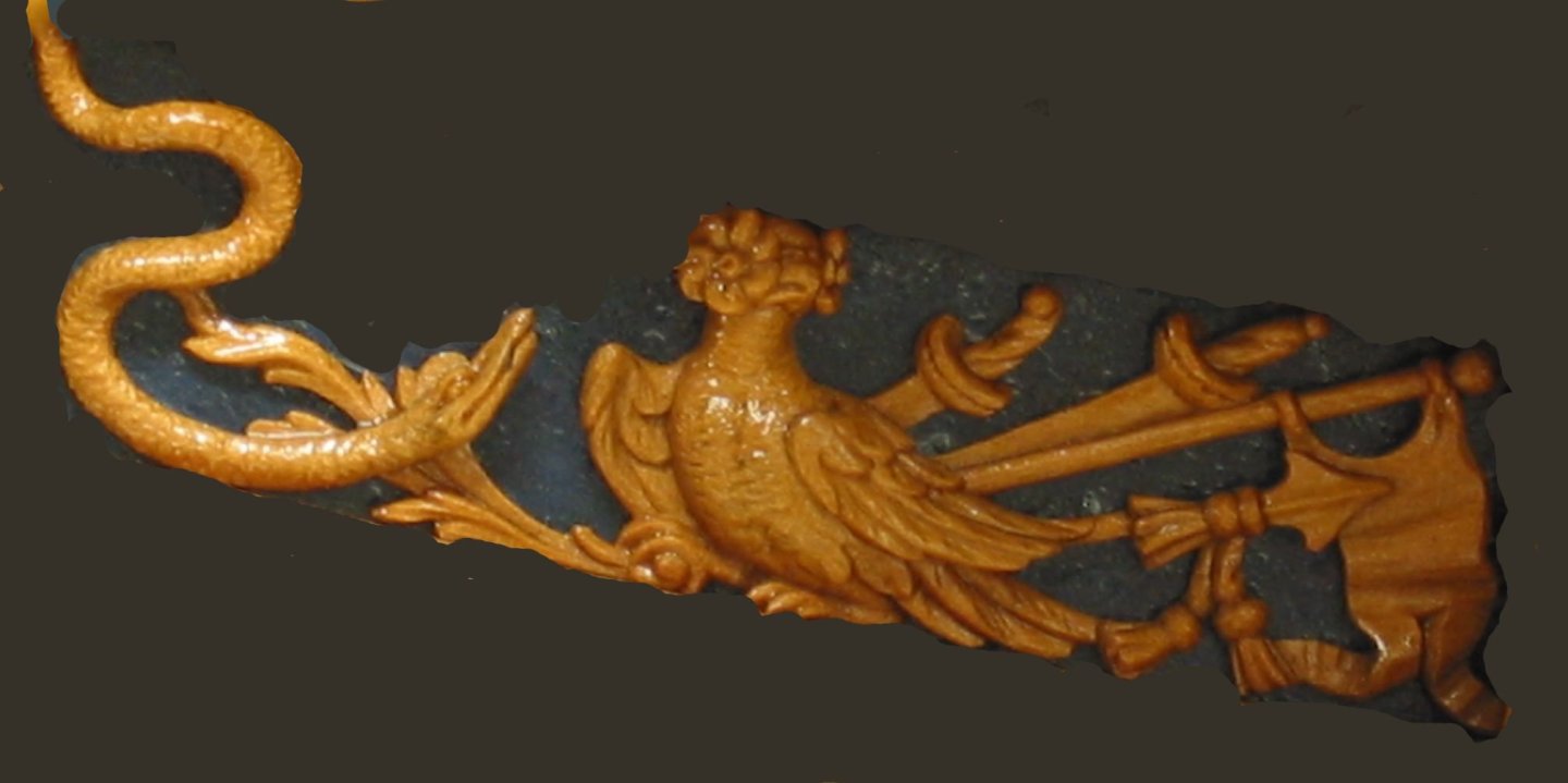
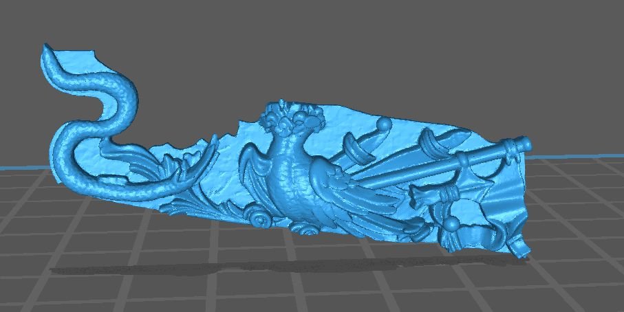
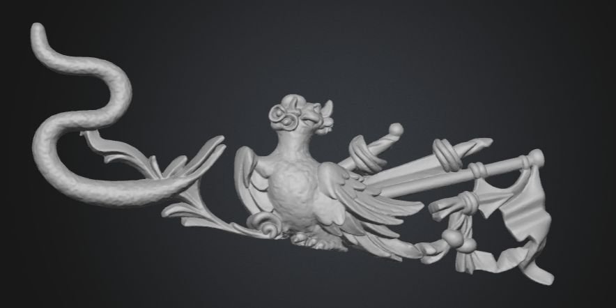
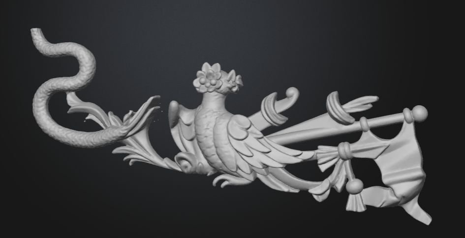
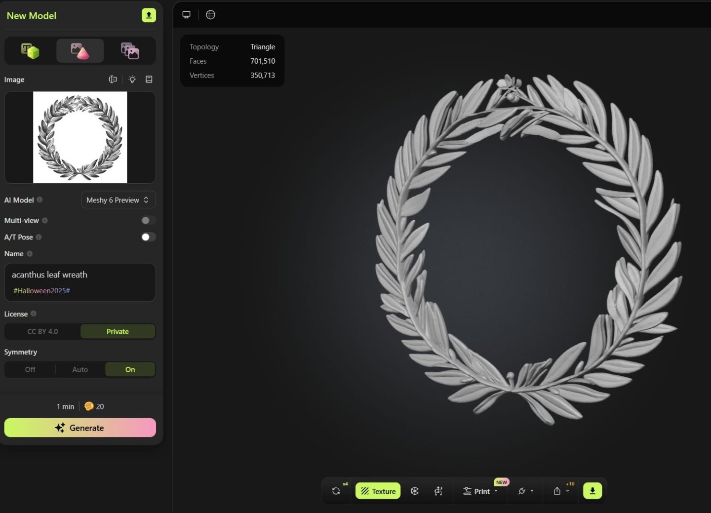
Now I am not a CAD guy at all. I know enough to be dangerous but really cant design a part to save my life. But thanks to the new idiot proof tools and software out there it really is easy as can be these days. Many are free and if they are not it really isnt expensive to use. So using really common software that folks are very familiar with one can create excellent 3D objects for a ship model, even somewhat complex carving. I will start with a rather simple 3D part. I need to redo my carving set for the Queen Barge. Its Acanthus leaf carvings are too difficult to carve as many of you know. I included Boxwood blanks to do just that in the kit along with resin cast versions. Those castings were done the old fashioned way and not 3d printed. So rather than hire someone to make them with CAD expertise (because I cant CAD, LOL) Here is a good, almost perfect way to accomplish the same thing. These tools cant be used for everything just yet but it gets better every day. First my original wood carving. Have a really good photo at hand. It is important to remove the background from these to isolate just the carving. A white background works well but a darker background works just as well for light colored objects. This method works best for bas relief carvings but has reasonable success for fully in the round sculptures. Here is one element of the three part carvings for my barge. I did these by hand. Now think about this for a minute....If you can manage really good photos taken of any contemporary model of the carvings, and remove the background it will work great too. Then sign up at Meshy.ai You can use the free tools available but it isnt expensive to sign up for the upgraded tools. They have a new "Meshy 6" version that takes images and converts them to 3d files. Now 6 months agao this didnt work nearly as well. For some things it still doesnt. But I think the results will pass for most model builders. The real secret is removing the background and the extra noise that will really screw with the AI brain...LOL You cant just crop that first photo of the model and upload it into Meshy. It wont know what to do with the background. You must isolate the carving as good as you can. Here is the meshy workspace. You can select to describe what you want with text (not the best option for specific carving on your model or other features. Best to go with the image to 3D option. Meshy version 6 doesnt have the option to use multiple images yet for a one part. But how often do we have multiple images of a carving or part at different angles. Sometimes it is just not easy to get those. So one photo will work and actually has better results as what other images of this carving would you need. So select the Cone or red "image to 3d option. Drag in your image and upload it. In my case that single carving. Dont worry about the other setting if this is your first time. After uploading your image simply click generate. In about 45 seconds you can see what the program created. This can be downloaded as n stl file and its ready for 3D printing...Or if you are a little dangerous, you can upload this file into any free CAD program and tweak it further. If you dont love what the AI did on this first attempt, the program lets you try again another 4 times on this project to create another slightly different rendition. Here is the slightly different rendition after asking it to retry. Yes it is not perfect but absolutely useable and you would be surprised how good some of them actually turn out. Now I cant emphasize enough how important it is to isolate what you want them to model. You must erase the background or paint the background away in photoshop. To show you how important this is. I have taken one of my photos of the contemporary model for Minerva....the trailboard carving. This is a hard one for the AI as the bird doesnt have a face, LOL. I was curious what would it do. Also the serpent has a face that may not be to easy for it to figure out. But I mostly want to show you how important it is to remove the background. Being lazy I did a half -ass background removable....its not even and not the same color etc. You can see where I left a lot with jagged edges. Brought into a slicer you can see how it did....not bad but not good either. A little better clean up of the background on the original image. Better. After tweaking the contrast and brightness of the original image of the carving...remember this is a bizarre image of a bird with a flower for a head. And the serpant head wasnt super clear in the original carving. But I wanted to show this exercise to demonstrate that it really is super important to have a good original image. You must get rid of the background noise. Adjust the contrast and stuff so the details can be seen better if AI could actually see. I dont know. So dont be discouraged if you can do CAD....I cant but this gets you pretty close. You can tweak these or what the hay...use them as is and 3D print them. Its a lot better than most can carve from boxwood and it takes only as much time as you want to devote to your original images. But this is a good starting point for the discussion.... To continue.....no need for it to be a photograph. You can do excellent work with a good line drawing as well. If your plans have good drawings of the carvings you can use them. Run through Meshy.... Here are the results. You can of course adjust the thickness and level of relief. You can also manipulate this in other free programs like TnkerCAD to make a pretty convincing gun port wreath. But this was just an experiment to show you folks the possibilities. Chuck


-
Lovely coloring on those. They will look great. You cant also just use the thinner that pools on the top of the can to brush on the high spots. It wont deepen the color and will instead lighten it. But you must do that before it dries fully. In addition...using some wipe on poly for this also works a treat. You just have to experiment. My guess is any thinner or such stuff will work the same. Chuck
-
Its not a matter of repricing....Its a matter of sourcing the parts. I still havent solved that one yet. Sorry. Chuck
-
If Chris somehow decides not to produce those as a kit, I will absolutely do so. This way folks can laser cut their own parts or cut them out the old fashioned way. I would have to remake the carvings for 3D printing for the Barge though. I hand carved those and had them cast the old fashioned way. Chuck
-
Yes indeed...I will be continuing that for sure. If I free myself from mfg kits I can spend more time building models. Those that I complete will either have their plans released here or possibly a Seawatch book. Or even other mfgs who want to produce them can have the design. Its just the mfg I am giving up. Chuck
-
Thankyou…i wish everyone had that kind of patience. I will keep you guys posted with my progress. I should be nearly done with restocking blocks by tomorrow night. I basically have all of my 3d printers running around the clock. I even set them up before I go to bed and let them run while I sleep. I havent even started making rope yet. Maybe later today. That is the most labor intensive. Cant just hit a button for that.
-
Its mind boggling Glenn. I literally have one package of .095 tan rope left. All other sizes are completely sold out. Gone. Crraaazzzy!!
-
Seriously guys....LOL I have heard of DOOMSDAY PREPPERS before but I have never heard of "Ship Model Preppers". I am not shutting down and retiring next week for good...its going to be many many years. So absolutely, positively no need to order a thousand bucks worth of rope and blocks with each of your orders. And I realize the Canadian tariff situation has boosted my sales a lot...but this is crazier than during the pandemic. As of today, only 2 days after getting back from vacation, I am completely wiped out of rope and blocks and other things. Literally. Its all gone. Sold Out. Folks are buying a dozen packages of every size and I must say it is an irrational response to me not making kits any longer. I have several years to go unless I hit the numbers tonight. Although with the amount of sales since Monday I feel like I hit the lottery. Its actually why I stopped making kits. I just cant handle mfg both without having a heart attack or a divorce...or both. I will send out these orders.... but yes I dont have a choice, my store is now shut down for the next few days or even a week so I can make more stuff for you guys to buy. Hoarding is a love/hate thing for me. Sorry to folks who are needing just one or two packages for a model they are working on...everything is gone. When I returned from Canada I had exactly 4 products out of stock. Two days later and I have 63. I think I mentioned yesterday.... I am tired, LOL. This may take a while. Its a crazy but interesting reaction from ship modelers. Somebody should study this phenomenon. All kidding aside, I thank all of you customers who bought stuff...really thank you!!! But does anyone really need 12 packages of every size of 3d printed thimbles. You will never build enough models to put them on, although I hope you all live long enough to come close. Chuck
-
Not before but certainly after. Once I hang it all up I will create a Library here of all the parts and fittings I have made so folks can just make them on their own laser cutter or 3d printer.
-
No worries….but dont wait too long. you should buy them a little at a time. Chuck
-
Time to insert the chocks... These are different thicknesses. The upper chocks are thinner than the lower. But they are same for both the upper and lower capstans. So there are plenty of extras. The lower chocks are concave along the outside edge...with the upper chocks being convex or rounded outward. see below. These chocks are cut oversized both in length and in width. This is probably the most time-consuming part of the project. But it is also one of the most important. Especially if you plan on going with an unpainted capstan. You want to show nice tight joints here...and properly shaped chocks. It could start looking sloppy really quickly. So first, sand a chock on its small edge to knock off the sprue nub. Not a lot. but just flatten it out. Then sand both sides so its a nice pie shape and your chock can slide all the way into position. The back edge should touch the column. The two sides should be nice clean and tight fit in their whelp slots. No gaps. Take you time. There is plenty of meat on these. You will be sanding them and testing them and then sanding and testing more. Test fit them until they slide in with a nice fit. You will grow accustomed to how much to remove and where after the first few chocks are completed. Below you can see one of the chocks test fir in the slots. note how far it still sticks out. This is by design. Take a sharp pencil and mark the sides where it meets the front edge of the whelps. Do this on both sides. These are complex little buggers with some crazy angles. But if you proceed like this it isnt difficult at all. And it will look like it should, with the chocks mortices into the whelps. A detail at this scale that you cant omit. Remove the chock at this point and use your pencil marks as a guide. Sand that angle into the front edge of the chock. Make it concave or convex depending on if it is an upper chock or a lower chock. But dont sand it all the way to your pencil line. Just in case you remove too much. This is when it is a good time to test it again and glue it into the whelp slots. Then carefully finish sand the outside edge flush with the whelps...and create the final finished concave or convex shape. Use a fine 320 grit sandpaper or file. Be careful not to round off the bottom corners of the whelps. keep the whelps the shape they should be. Its all too easy to be impatient and rush this with sloppy final results. When you are finished....apply some wipe on poly and paint it red. Take your time. Its very easy to leave a lot of paint globs. Thinner coats and many of them. I used acrylic paint from a tube. Below you can see how I tested its fit on the base. Just slide it onto the stick you left in the base with the pawls. Note how the capstan still turns and the pawls engage.\ In the photo below you can also see the small bolts that I added. For the bolts on the whelps and chocks I used 40lb black fishing line. I pre drilled the holes so the fishing line was a press fit. No glue is needed. Just push in some fishing line and use a sharp #11 blade to slice off what sticks out. Slice off the excess so that just a small amount of the line stands proud of the surface. This does a great job of simulating bolts. The columns are being tested again just to see how they look as well. This is when you should examine the bottom of the capstan. Does it sit flat on the base. Note how the bottom whelps and chocks are all flush and even, I sanded the bottom of the capstan just a bit to make it all flat and even so it would sit right on the capstan base. No gap between the capstan and the base here. When you are satisfied, you can glue the capstan onto the base and the center stick used to align it.


- 23 replies
-
- 10
-

-
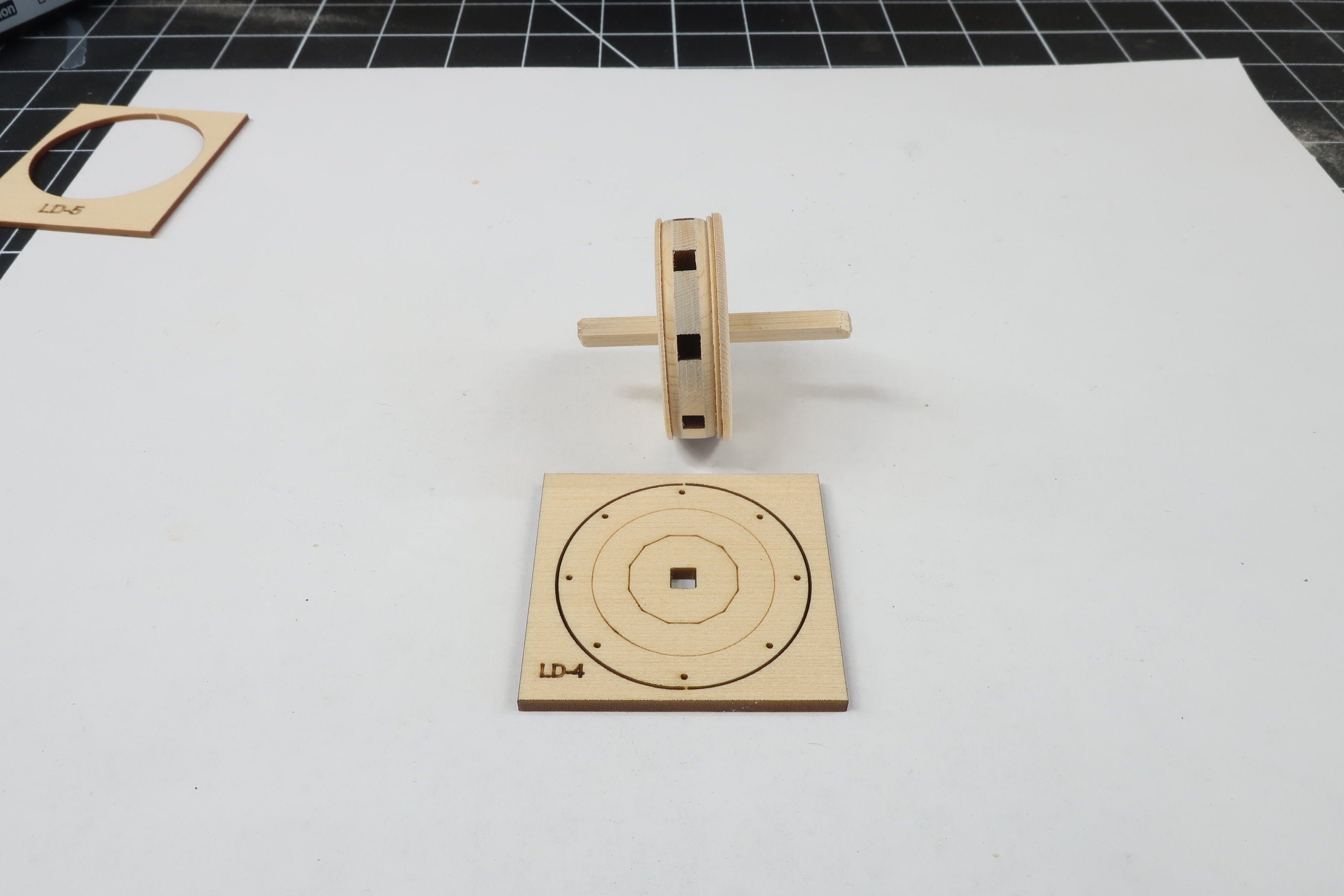
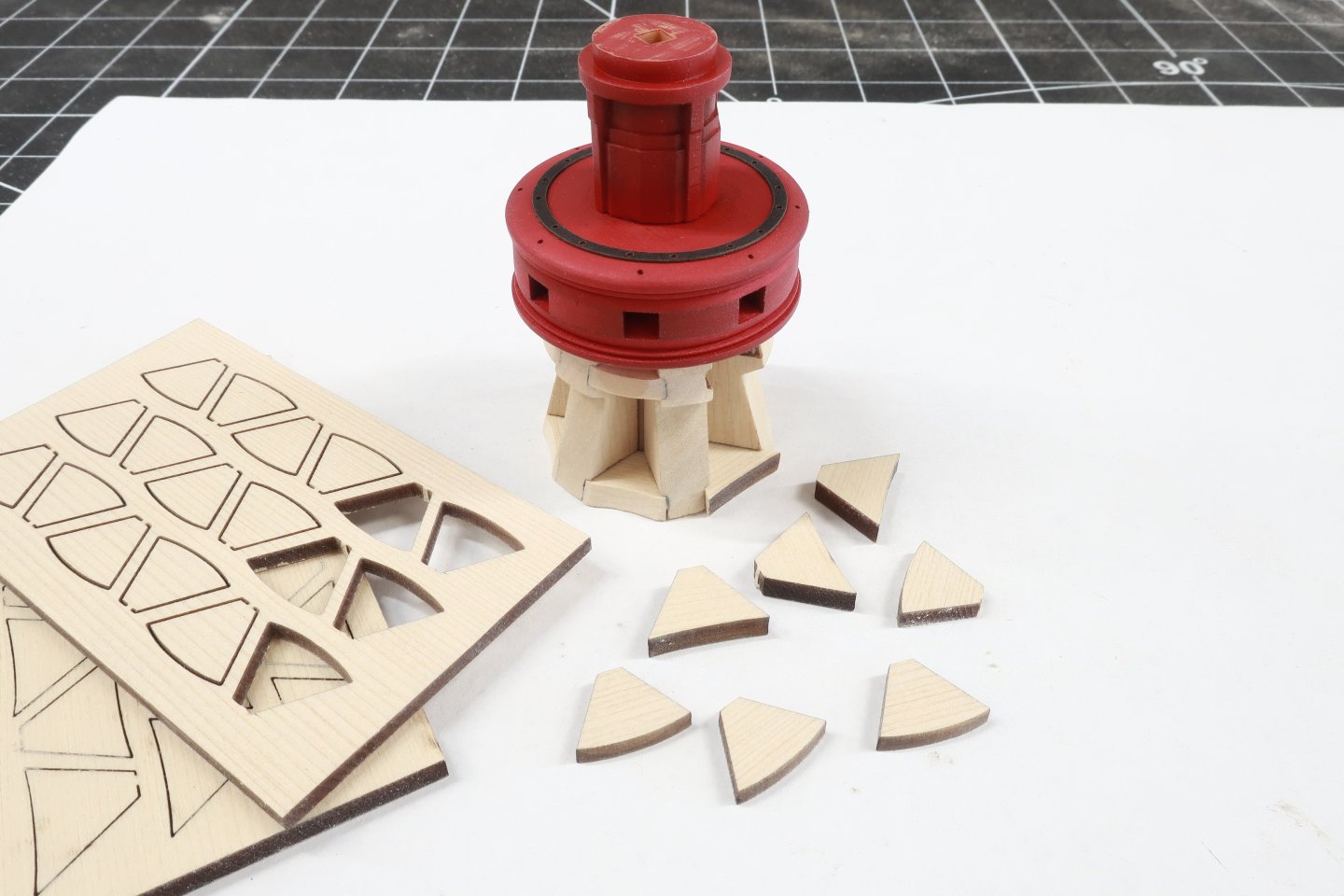
Time to add the whelps...Parts for the lower capstan. I mention this because the whelps for the upper capstan are indeed different. So take care when finding them among your laser cut parts. These are pretty straight forward. They are laser cut and 1/4" thick. They have engraved slots for the chocks on both sides. Before you even punch these out of the sheet, sand both sides with 320 grit to clean them up and prepare the wood surfaces for final finish. Then punch them out with a sharp number 11 blade and sand the edges free of laser char. Now the laser engraved slots can sometimes be a little rough. So take a file and just give them a few passes. You dont have to go crazy here. But sand the sides and bottoms of the slots a bit smoother. But dont make them any wider. That would be bad. I will also mention that although I am using 1/4" thick whelps, if you are laser cutting your own pieces, you could swap out the thickness with 7/32". The actual is somewhere in-between and after testing with 1/4" whelps I determined they looked just fine. But really, the same would be true if I used 7/32" thick whelps. Then glue them to the faces of the center column. They may be slightly wider than the faces on the center column but that is ok. Just add them all around the column and evenly space them. As you go, note how those slots should be even from one whelp to another. This is where you will be sliding your chocks into in the next step. If the slots are higher on one whelp then the one next to it, that is not good. It means you over sanded the top edge of the whelp. No worries there are extras. NOTE...the bottom of the whelps should be flush or nearly flush with the central column. If they are not. No need to worry just yet. Wait until after you add the lower chocks and we can access and move forward. Its not that big a deal. Especially if they are shorter than the column.

-
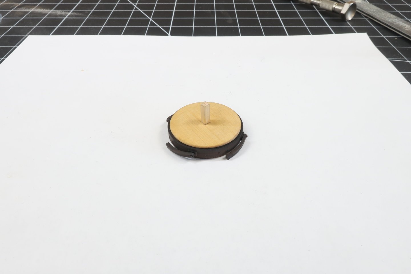
I have added the top central column piece and painted that red as well. you should have a small length of that 1/8" strip hanging out of both sides of the lower drum. The 3d printed columns simply slide onto it. The one I painted red is placed on top. The orientation doesnt mater. But make sure the top is correct and dont add it upside down. See pic below. Then I took one of the remaining 3D printed central column parts and glued it onto the bottom of the drum. Make sure you pick the right one. Its the one WITHOUT the small round section on it. Make sure that you sand the bottom of both sides of these 3D columns flat. Sometimes they have some extra cured resin on them and the small nubs from the supports. So use a sanding stick to make them flat. You can also glue the laser board black ring to the top of the drum. No laser etched reference for this ring. So just do you best to center it using the center column and outside of the drum as a reference guide. Its starting to come together nicely.
-
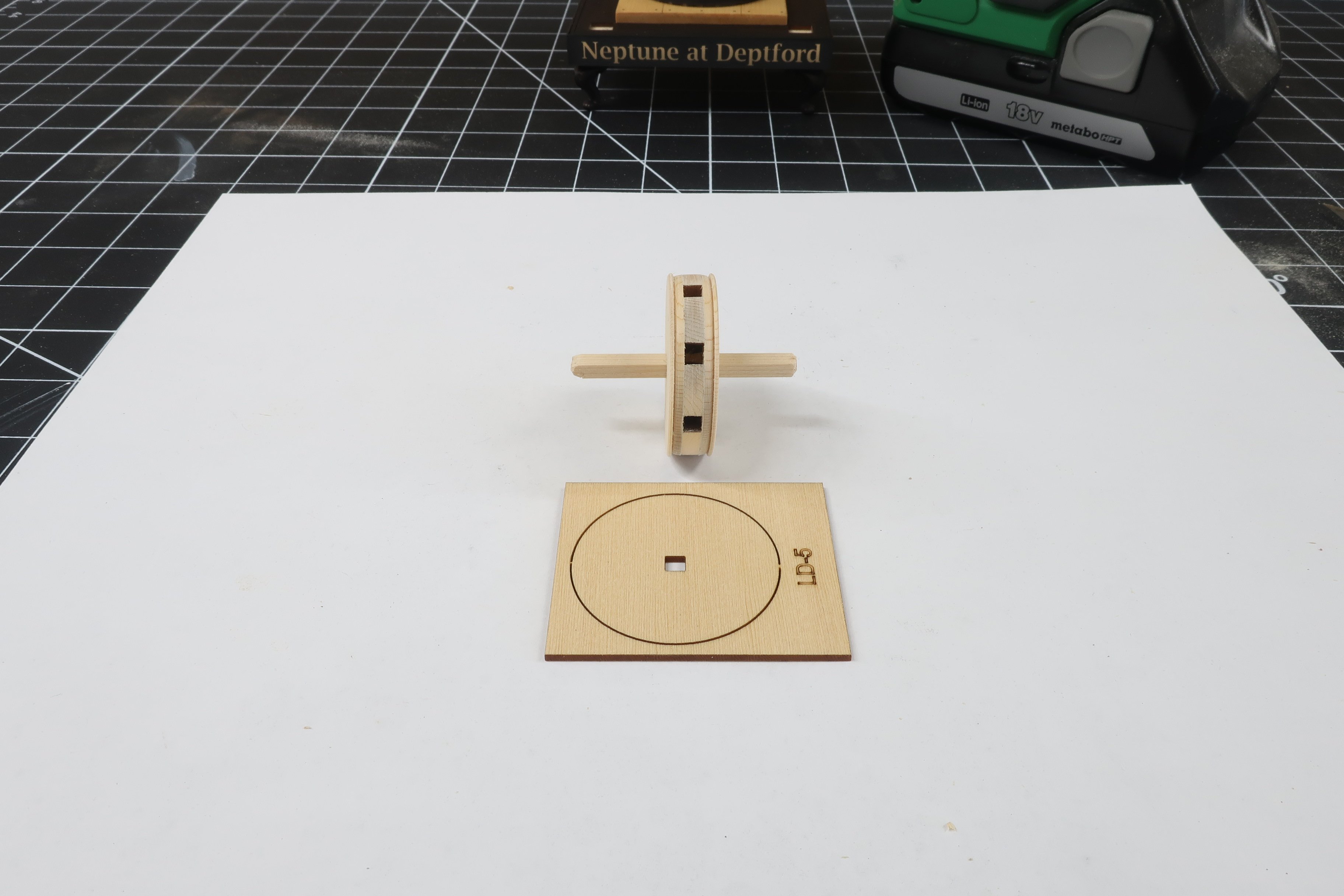
Ok lets start on the lower capstan... You will need LD 1 and LD 2 parts. There are two LD1 parts which are 1/16" thick. LD2 is the gear-like part (1/8" thick) that when sandwiched together will make up the center of the lower capstan drum. Slide these onto another short length of 1/8" strip as shown below. They can be glued together but once again, dont glue it to the strip. Chock it your drill again and sand away the laser char from the edges. But in addition to just removing the char, the profile of this assembly is rounded. Check the plan. You can see how the edges were rounded off. Now if you plan on painting the capstans red like I did you can rest a little with the sanding. But if you want to go with a natural finish, really make sure you get the char off. Especially remove the char from the end grain areas. You might want to apply a thin coat of wipe on poly just to see if it gets really dark. Then you know you have to sand more off. While still on the drill use some fine sandpaper (320 grit or even 400 grit) to give the wood a nice surface for painting and finishing. Then get parts LD3 ready. LD stands for lower drum by the way. Glue those onto the assembly. One on each side. These are very thin so dont force them or they will break along the grain. Then chock it up again and start sanding and shaping. These discs are larger in diameter with some extra size on them. Dont be afraid to remove the char and reduce the diameter. Sand the edges and soften them. They are indeed also rounded off a bit. Refer to the plan to see the profile of each layer you add as you proceed. Below you can see how the previous discs were sanded smaller and profiled. Next up is LD5. This is 3/64" thick and on what is the bottom of the drum. You know the drill...literally. Glue it to one side of the assembly and insert back into the drill. Sand to match the plans. Examine my progress below. Now its time for LD4. I since removed some of the reference lines but it looks pretty much the same. Glue this on to form the top. Only this time, you must make sure those small holes are lined up with the square opening in the drum. These are the holes for the capstan bar pins. Same deal with this layer. Glue it on and then chock it up and sand it. Dont be afraid to reduce the diameter. Check the plans to see the final profile of the entire drum. NOTE that the this piece is 5/64" thick. But as you sand it with your sanding stick, you can reduce the thickness along the outside edges. You need to create more of a slight dome shape to this layer. Use the plan as a guide to determine teh final thickness along the edge. This completes the lower drum. But I decided to paint at least the first few coats of red paint at this stage. Also get your 3D printed center column ready. You have 3 of these. This is the shortest and most interesting of the three.


-
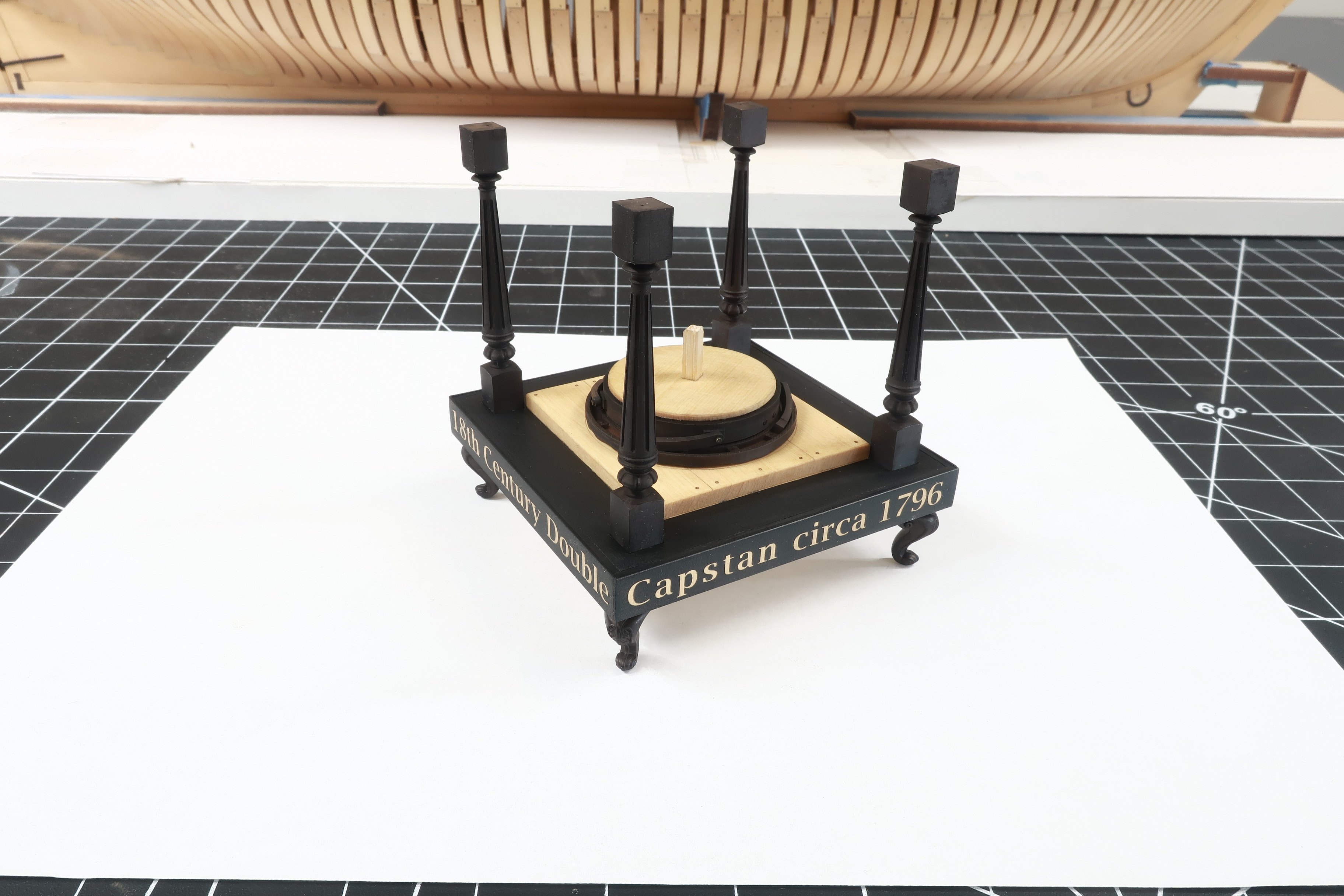
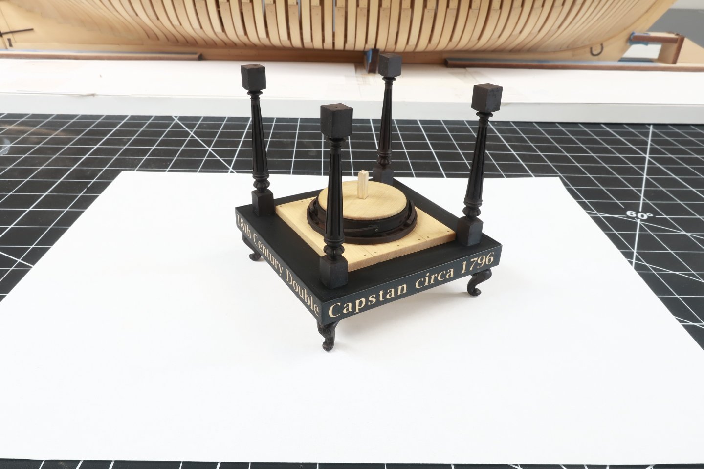
Its kind of funny and I thought I would mention this... People are contacting me saying that I am crazy to just give away an entire kit design....free. Even if these are just small projects...for now. The truth is I have more fun building and designing these things. As I have gotten used to using these technologies to make them they are literally kit-ready when I finish. This is how I will make my scratch built models when I retire. The fun is in the design and in the building for me. Not the mass production and factory stuff. Plus I am convinced that so many people will have easy access to the machines needed to make a personal kit for themselves as the machines are really cheap now. If you are a scratch builder and bought a sherline mill and lathe along with a byrnes saw and thickness sander, a laser cutter and 3d printer is just about the same price. Its just another tool. This doesnt mean that we will see several hundred kit mfgs popping up because the real skill is in the design and engineering and materials used. Anyone can use the machines. Not everyone can engineer these things. It also kind of sucks to mass produce all this stuff as a one man operation. So why not just be a mentor of sorts and teach the techniques and skills to operate the machines so everyone can use them to their fullest. I designed and built this capstan model in two weeks because it was a subject that I always wanted to model. So it was a nice personal project to experience. I knew it would be inevitable that if folks saw it they would want one. But its impossible for me to mfg all these commercially. I could be so much happier and much more prolific designing these things if I knew I didnt have to mfg them afterwards. I could sell the designs to another mfg or whoever but not for these small ones. Knowing what they pay makes it not worth the effort. So why not give them away. At least for the small ones. I would never design an HMS Victory kit and just give it a way after 3 or 4 years of work. But these small projects...why not. Its the design side that you need a unique brain for. For example, this capstan project. I am quite happy with how the design turned out if I dont mind saying so myself. That was a very rewarding experience to see how it all came together. I hope you guys will get a better appreciation for the design and engineering side as I release these smaller projects here. All of the parts are being released and I guess you could scratch build them all by hand using traditional methods too. But I am spoiled now...so no more metal work and soldering for me. My sherline mill and even my lathe are just collecting dust on a shelf in my shop now. Just some thoughts I figured I would share as so many of you are contacting me saying I am crazy...LOL. ALSO...It doesnt hurt that I have a sugar mama at home who takes care of the bills. As long as she tells me I dont need to kill myself anymore working 7 day a week and 10 hours a day making rope and blocks and kits....I wont question it. I am tired. Chuck
-
In this photo I am testing that pawl assembly on the model. Remember no glue as it needs to turn. I am also testing the fit of the four 3D printed Columns although we wont need them yet. They fit pretty darned good in their respective square holes. Those will be added much later.
-
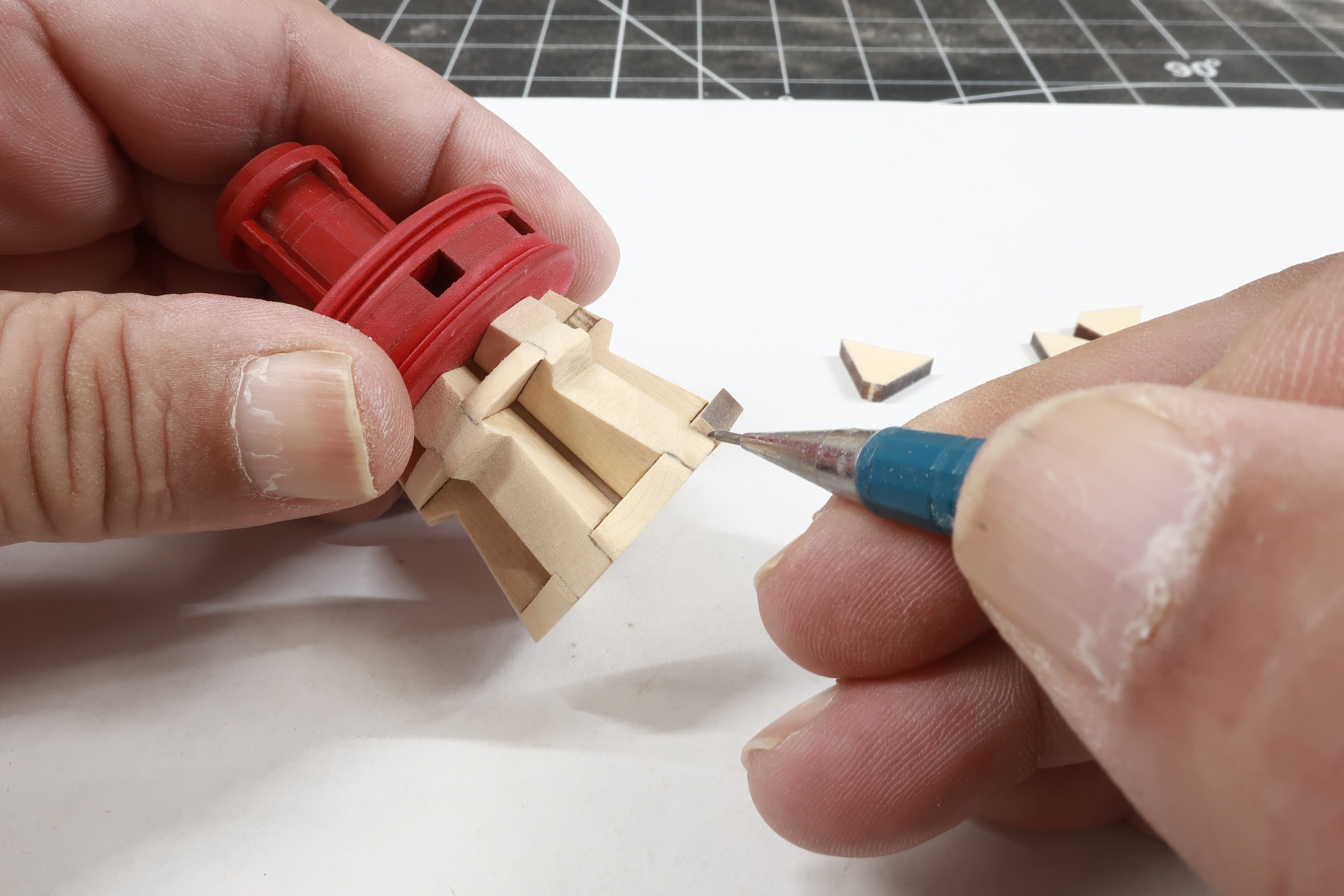
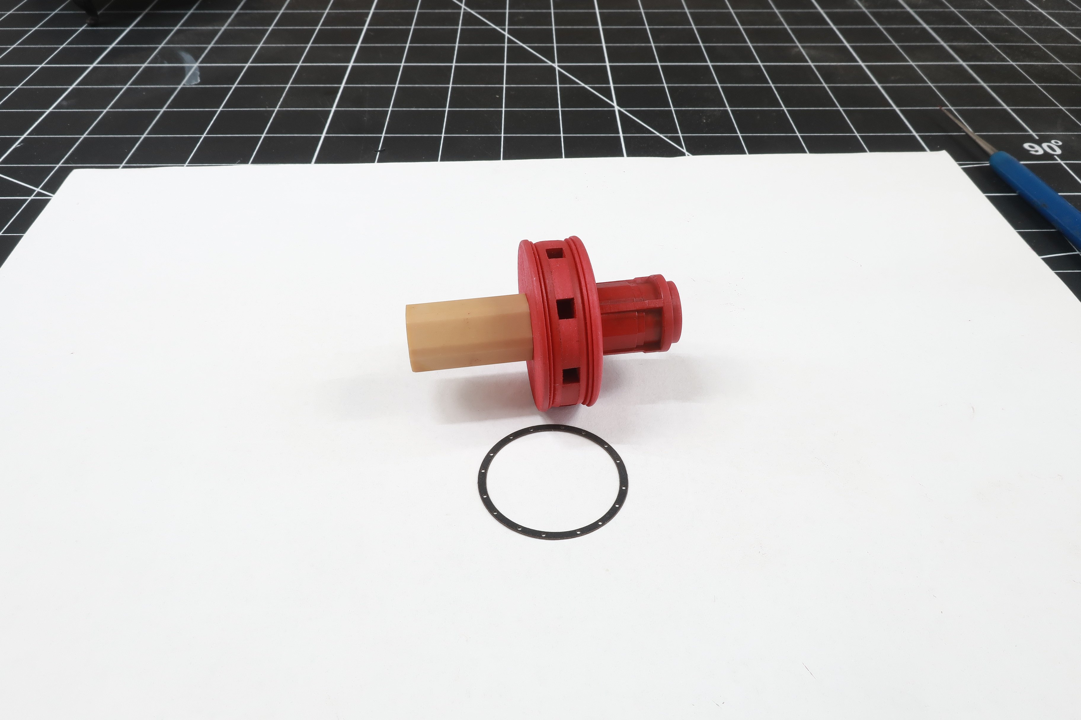
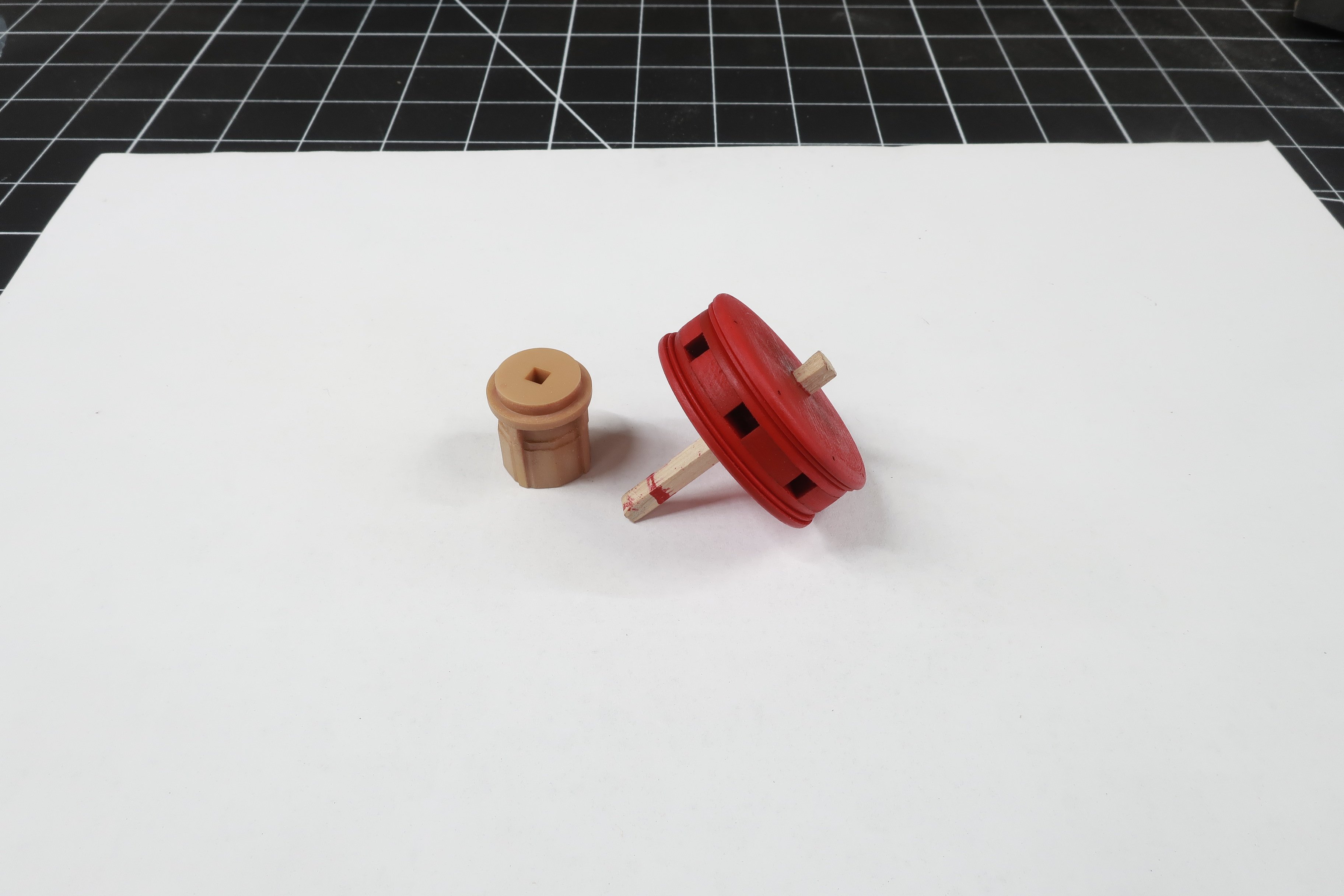
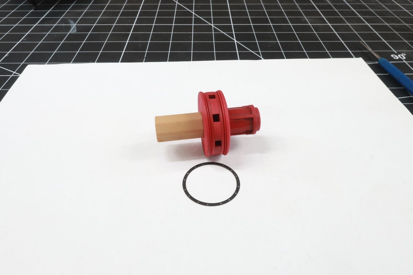
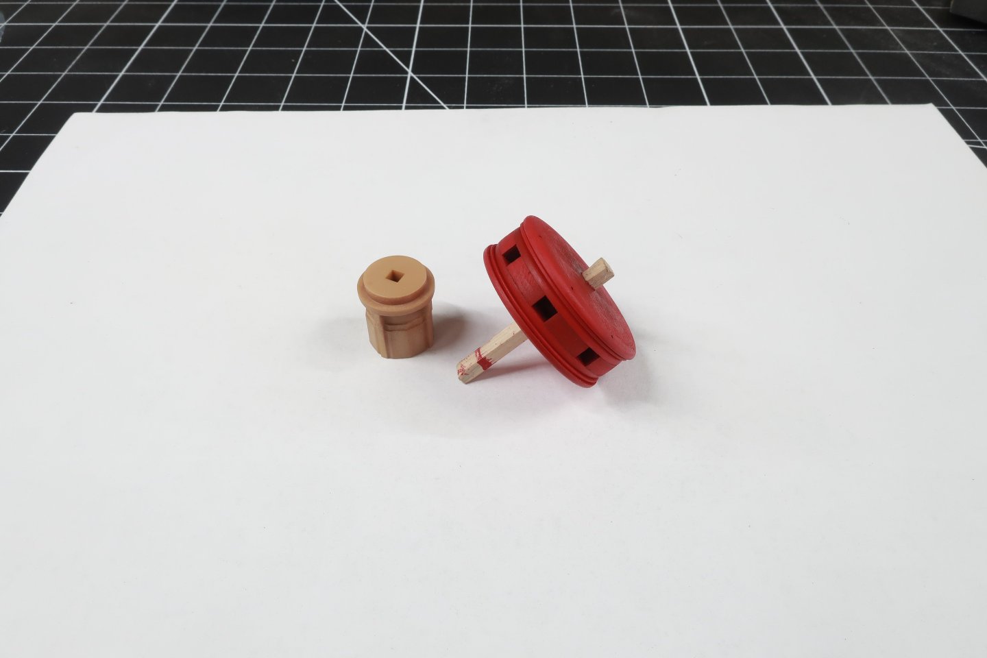
Lets add some pawls.... You will need a brass bar that is 3/64" dia. Cut the brass round wire into four small lengths. Maybe 1/4" long. Take your 3D printed pawls and glue one of those brass pins into the hole of the pawl. Those holes are should be a nice press fit. If its too tight then your 3D printer settings were too high. Your exposure setting is too high which makes the hole smaller because of over curing. You can glue the brass into the holes. Remember this is going to be a working capstan model. You need to drill holes through the ring and into the 3/16 middle layer. Use a 3/64" drill bit or very slightly larger. The brass pins of each pawl are inserted into those holes. If you want this to be a working capstan model dont glue them in the holes. Again they should be a press fit so the pawls actually move and pivot. I blackened the ends of the brass pins. I also added a light coat of weathering powders to taste to give all the metal parts a look that I prefer. I used some browns and rust colors....very light. Dont over-do the weathering. NOW...if everything works out correctly.... You should be able to place this assembly into the capstan pawl base. You glued this to the base already but I am using an extra one here for the photo. It should just sit in there. It should not be too loose or even too tight. Basically part C should be the exact size you need to sit in the center of the pawl base. This will NOT be glued in position. You want it to rotate and for the pawls to engage along the sides. Give it a test. Testing....below. Then just set the base and this lower assembly aside so we can start building the lower capstan. Note the small length of that center stick still sticking up from the pawl assembly. Keep that there as you will use that to mount the finished lower capstan.


-
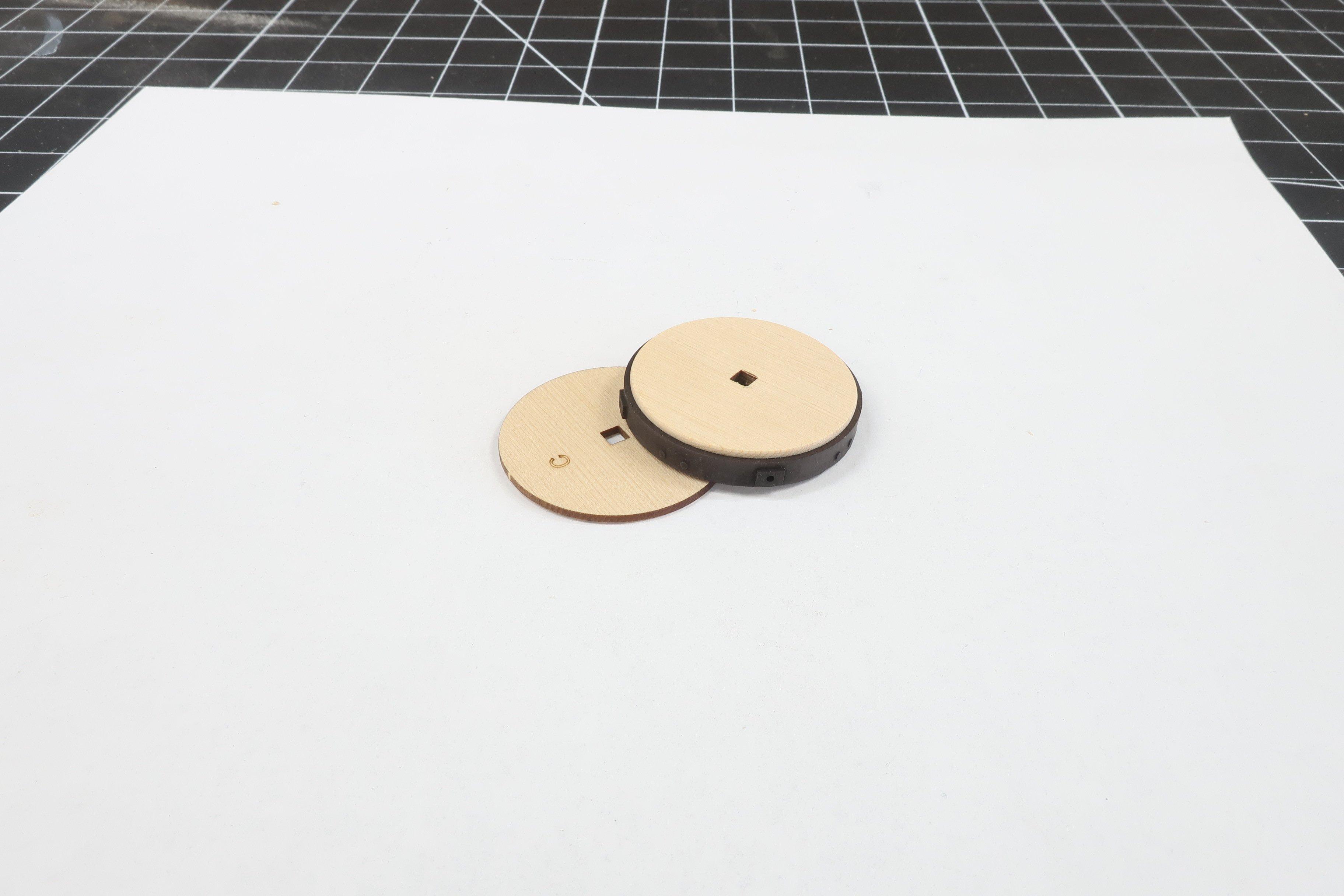
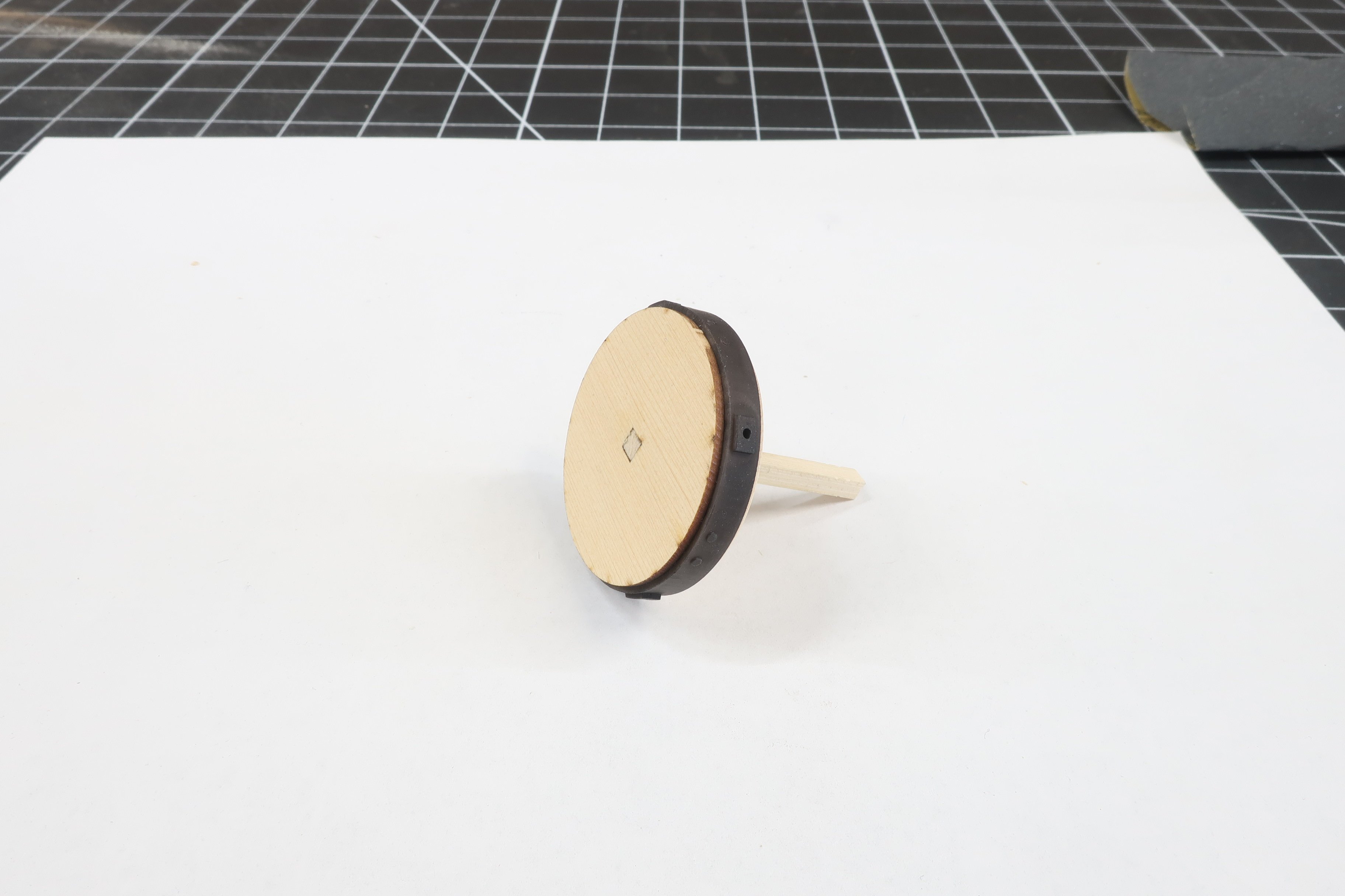
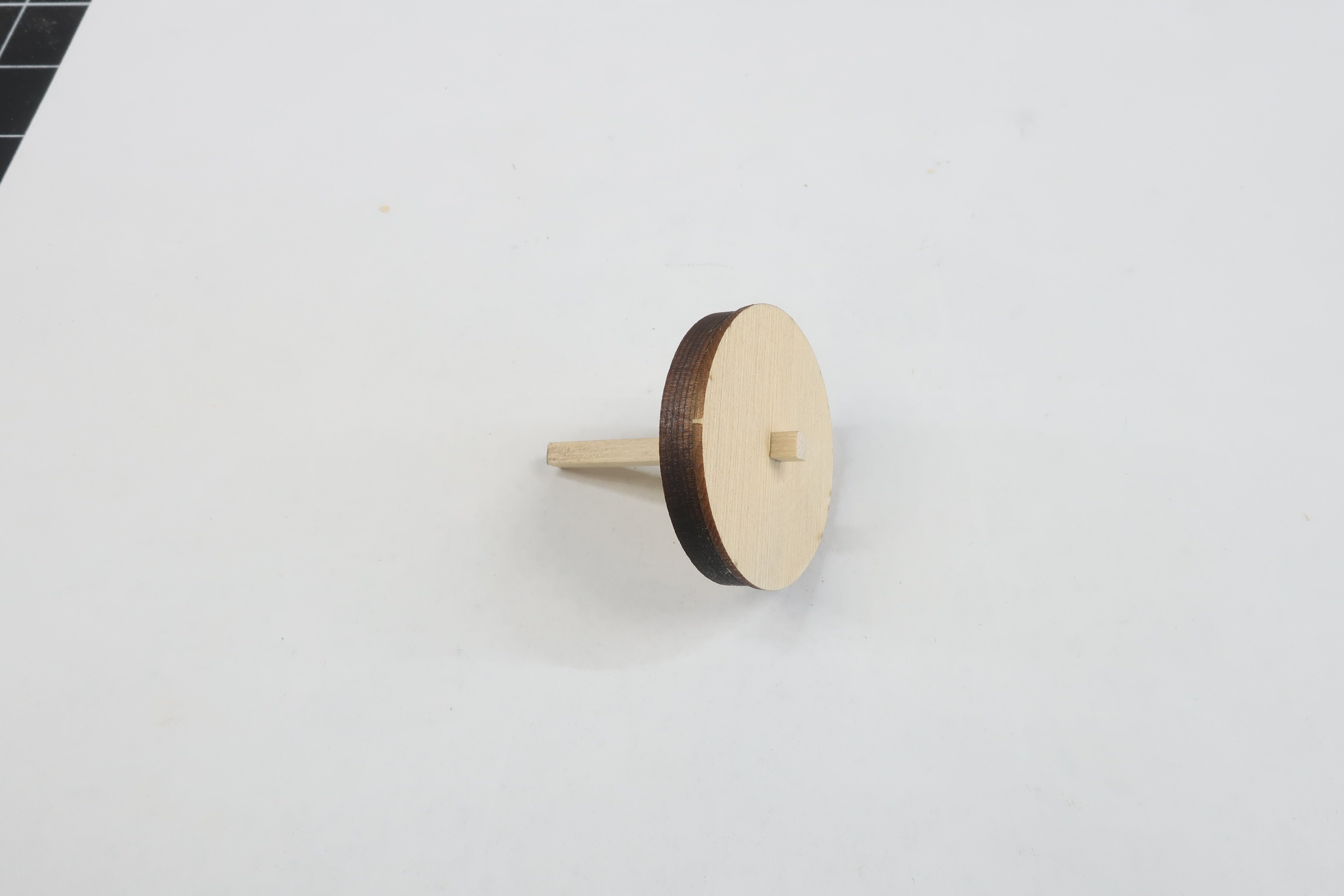
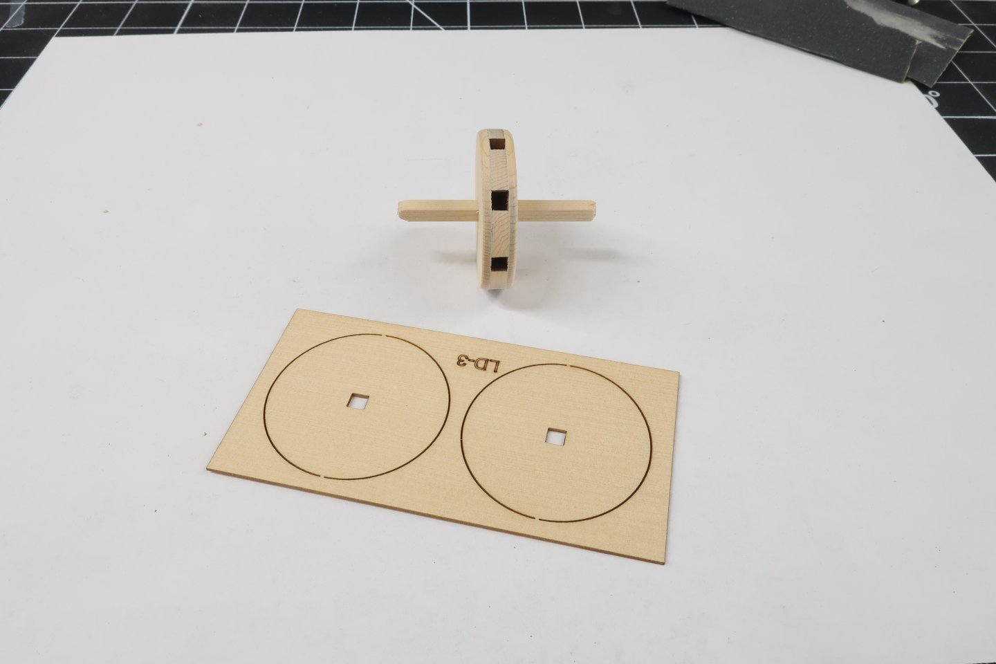
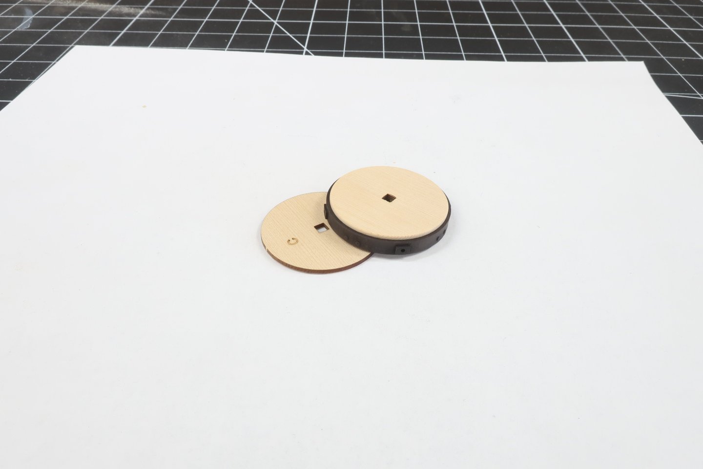
You will need part C and the 3D printed ring.... You will notice the little rectangles with holes along the edge of the ring. They are closer to one edge than the other. Slip this onto part C up against the lip created by part A. Just slide it on there!!! No glue is need. This should be a nice press fit also. If not and it is too loose then add some glue. That just means that your laser Kerf was to large and your laser cutter settings were set too high when you cut that disc. This made your part B slightly too small. Its an easy fix and not a huge problem. Cut another on lower power or just use some glue. Then take part C and slide that onto the stick. On the other side that doesnt have a thin disc yet. Face the etched letter C towards the center so you cant see it although it doesnt really matter. See below. We are not going to sand any laser char off the edge of part C. The only thing you might have to remove is the small sprue tab that supported it in the laser cut sheet. Just a few swipes to remove that nub. Glue the disc C to part B as before remembering not to glue it to the stick!! Sand teh stick flush to the bottom of side of part C as shown. Leave a little bit of the stick standing up on the other side for later. It also creates a built in handle for the next step.


-
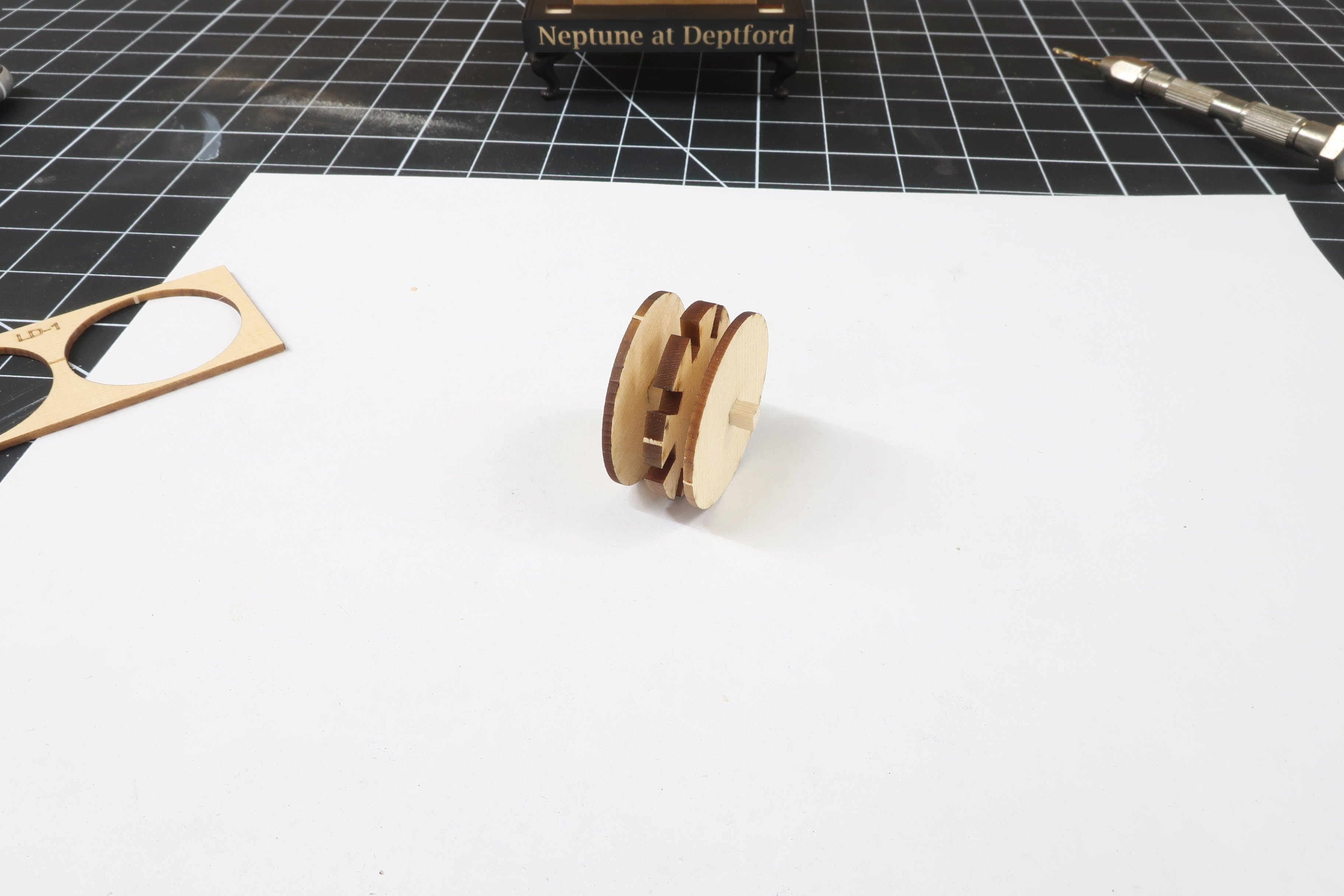
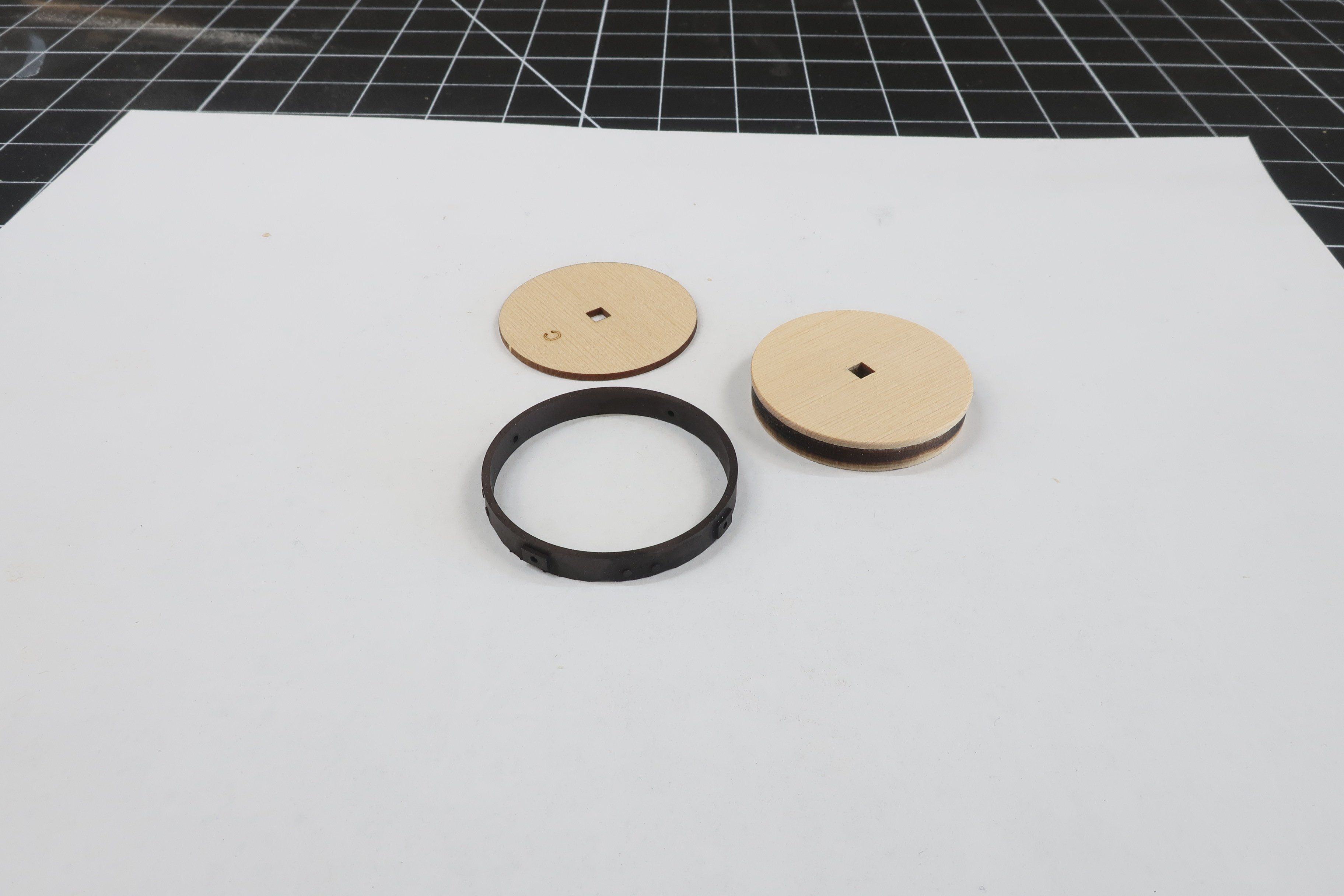
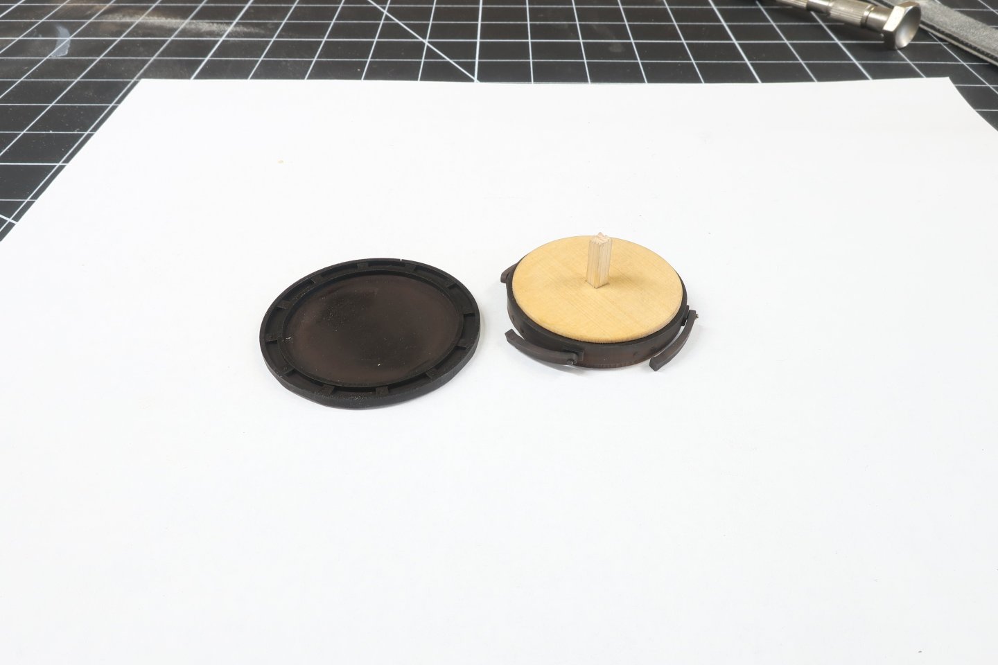
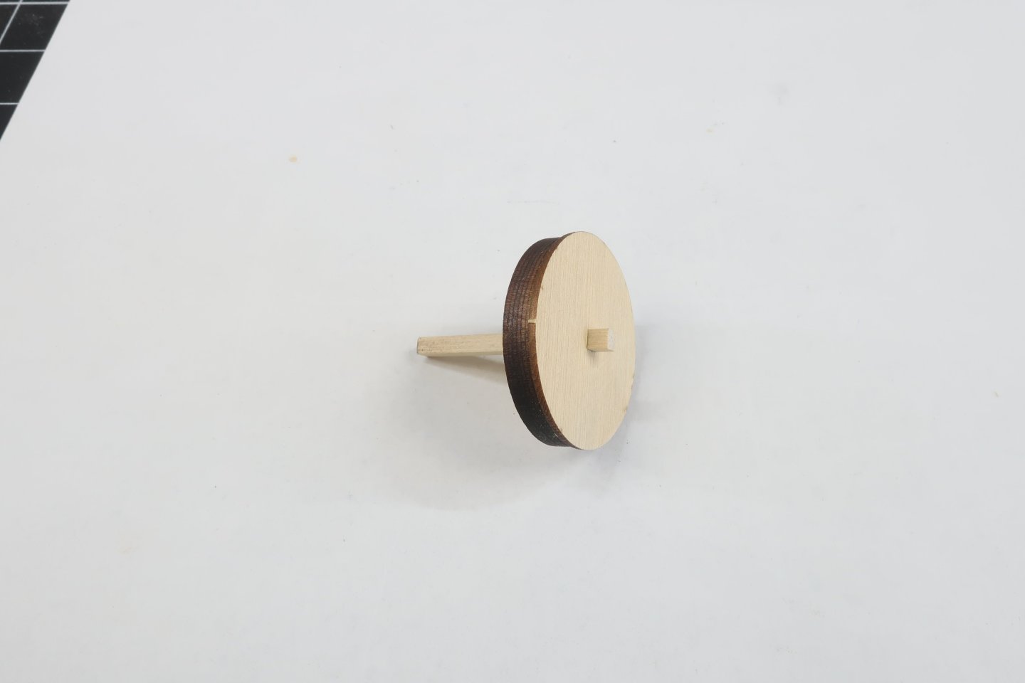
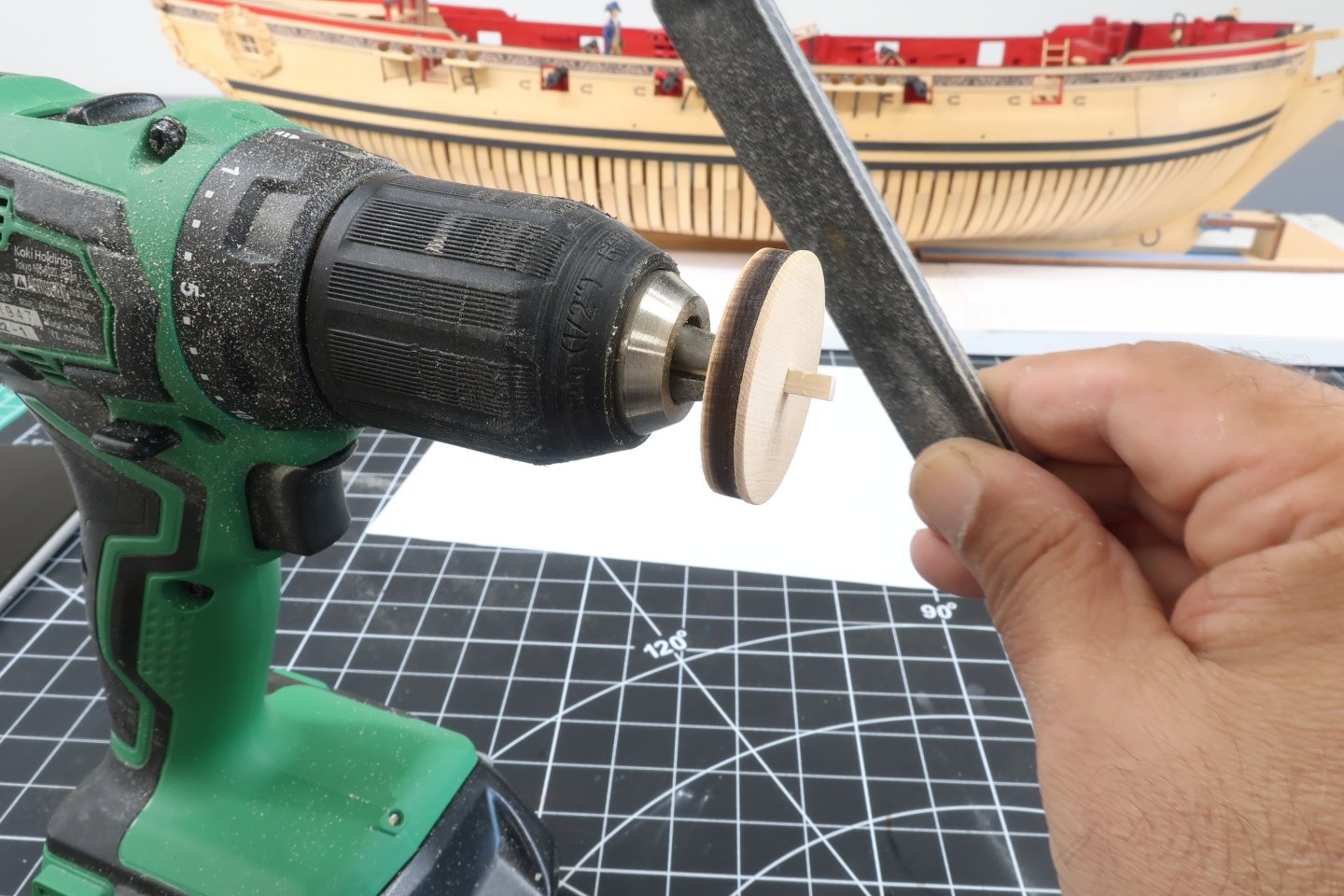
Using the strip insert it into the 3/16" thick part B. Then take part A (3/64" thick) and insert that so the laser etched letter A is facing the laser etched B. Glue the two layers together. BUT....IMPORTANT. Dont glue the two layers to the center strip. You will be removing it later. This is just for registration. The two layers should be a press fit in that center square hole. You dont want it too loose. If its too loose it will fly off in the next step but there is an east remedy for that. Mill a slightly larger strip....or if the strip is too tight. Sand it smaller so its a nice press fit. Dont force the thinner layers onto a strip. It will certainly split along the grain. You can just laser cut another should that happen but its better to adjust the size of your strip if needed. Now the fun part... Chock the strip in your cordless drill. Then on a speed that is comfortable for you, use a sanding stick to remove the char from the edge of part A ONLY. Just a light sanding. You will notice that part A is larger in diameter than part B and that is what you still want after you remove the laser char from Part A. Dont over sand it. This happens quick so use a light touch. My sanding stick is a 160 or even finer grit.
-
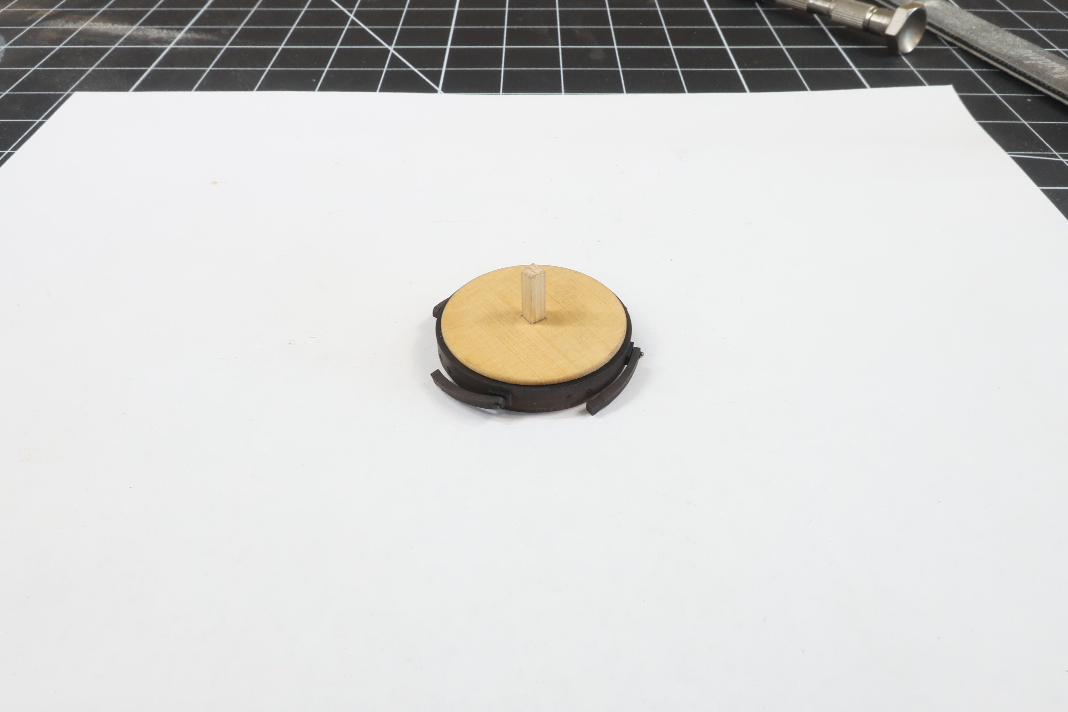
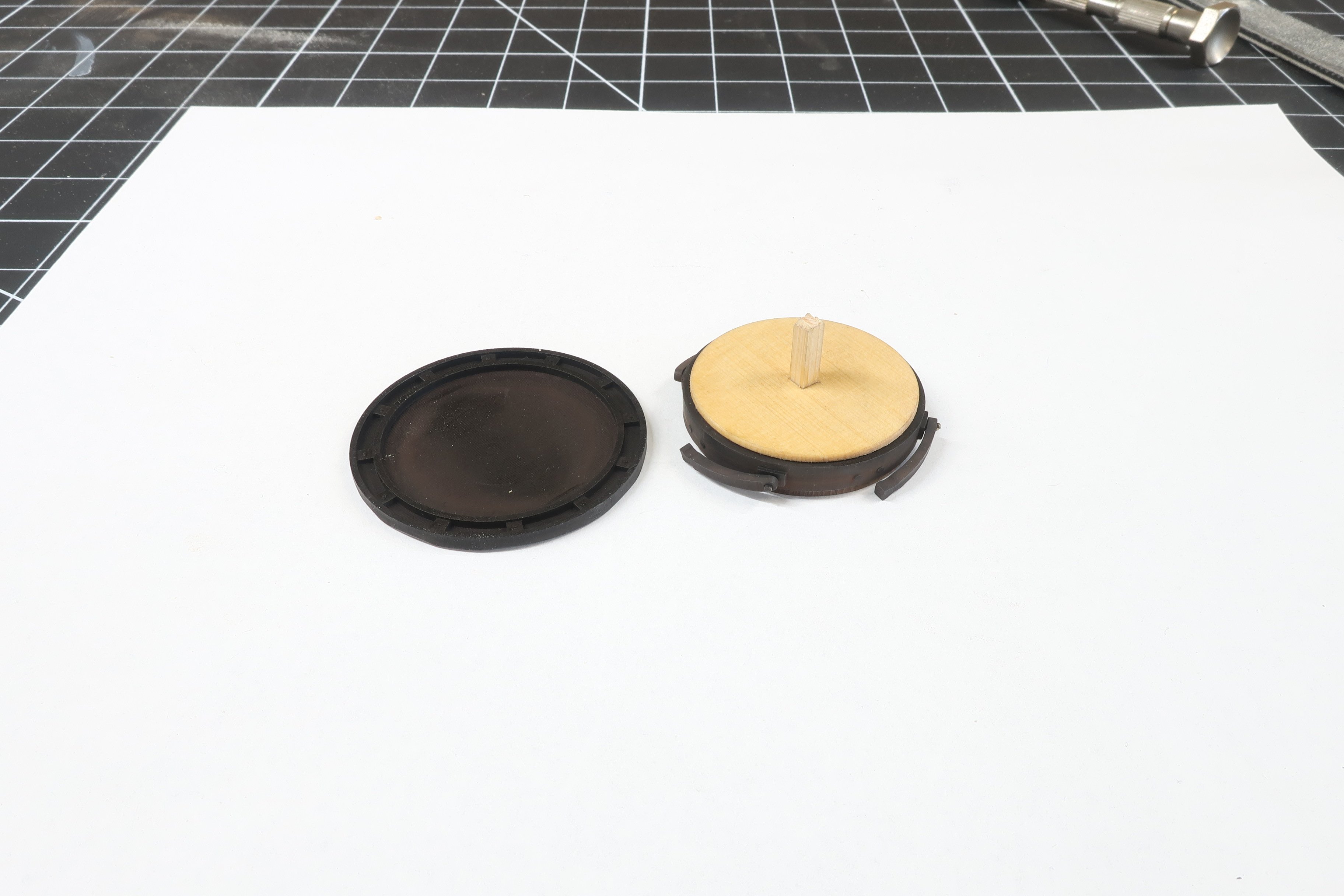
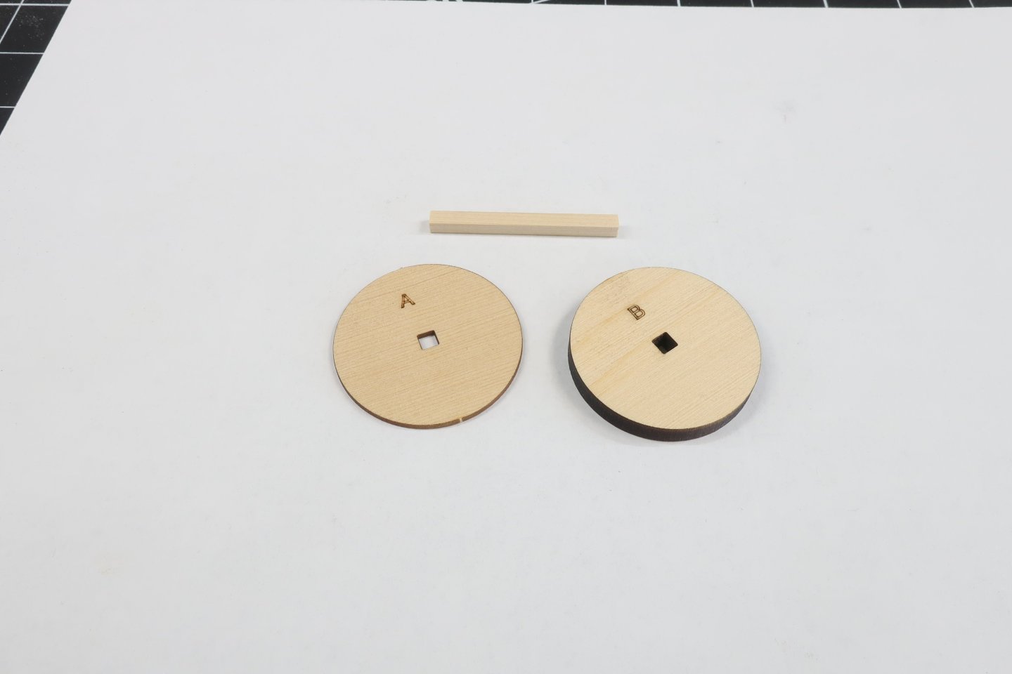
You will need parts A and B next. In addition you will need a 1/8 x 1/8" strip. Any wood will do but I am using a cedar strip. Just cut a small length for now. Maybe an inch long or slightly longer. You will need a few more of these for various assemblies on this project. So cut a nice 12 to 15" strip and keep it handy for the entire model.
-
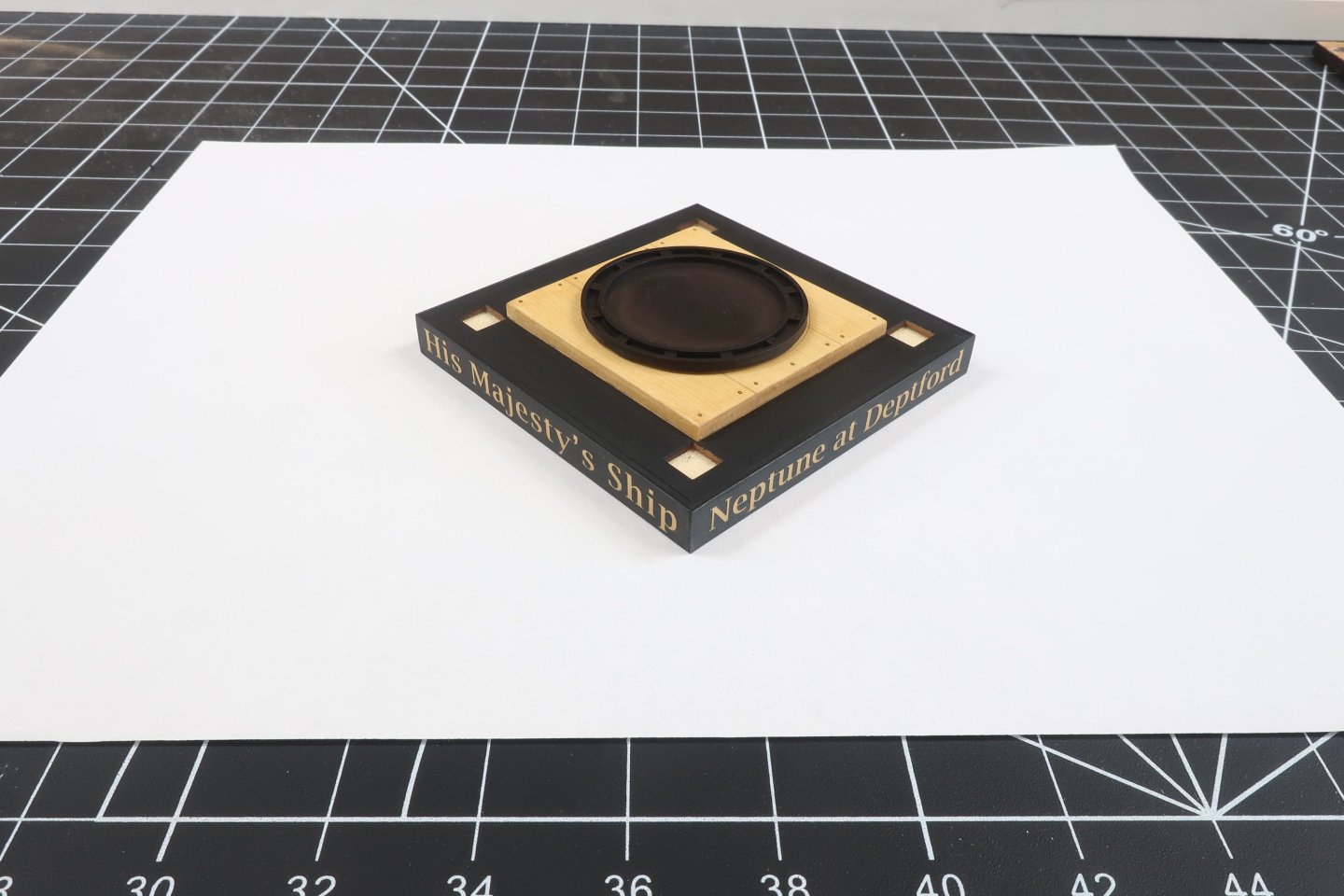
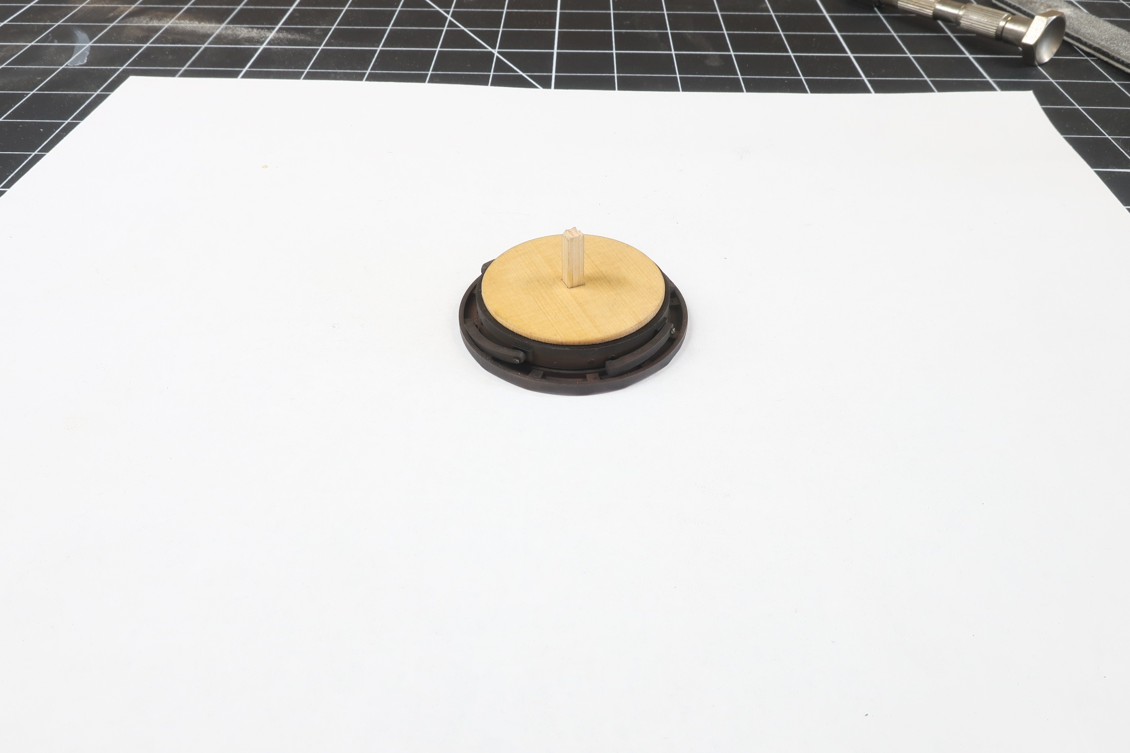
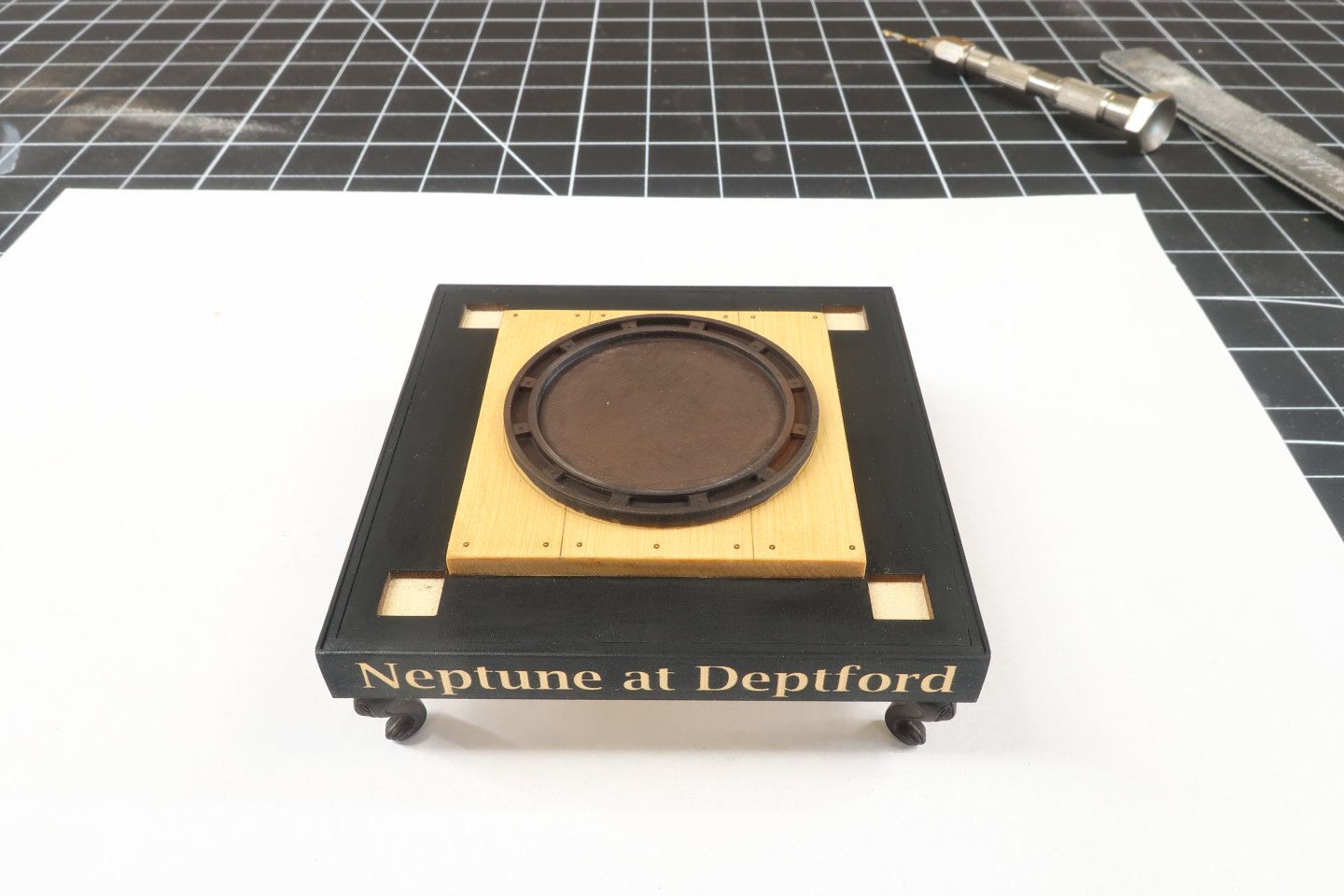
You can now glue the four 3D printed legs to each corner of the base. You will have noticed by now that the width of the lettered sides is wider than the base. This creates a lip around the entire bottom when upside down. This make positioning the legs so easy in each corner. Just but them against the lip in each corner.
-
Next you can glue the 3D printed pawl base on top of the capstan partners. It will fit right in the laser etched circle on the top of the partners. Its orientation doesnt matter but just center in that etched circle. I used CA glue for this. It does a great job gluing the resin parts to the wood parts. But you do have to position it quickly before the glue sets. So keep this mind. Dont dilly-dally with getting it centered.