-
Posts
9,660 -
Joined
-
Last visited
Content Type
Profiles
Forums
Gallery
Events
Everything posted by Chuck
-

Mara thread - what colors do you use for fabricating ropes
Chuck replied to Sterling59's topic in Masting, rigging and sails
You are welcome…what really helped me save money and pick the correct colors was simply to pay the extra 10 bucks and buy the Guttermann color chart. Made with the actual thread. I have it and the colors are spot on. Its still hard to pick a color though. -

Mara thread - what colors do you use for fabricating ropes
Chuck replied to Sterling59's topic in Masting, rigging and sails
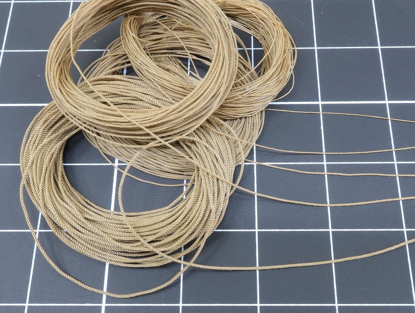
Choosing the right color…its a very personal choice. Here are a couple of choices. I am seriously considering NOT going dark brown for standing rigging on Speedwell as I mentioned earlier. But rather than use the same Tan color I usually use for running rigging, my thoughts were to go slightly darker with the tan. Considering it will be used for both and after looking at so many models rigged in this style I am making some test rope and will choose one. Eventually. Here is my normal tan alongside one that is a shade or two darker for this style of rigging. Too dark? Or is the light one ok? You are correct to ask which color but in the end it is a very difficult choice. Excuse all the dust on the model. That happens so quickly. I am selecting my test threads based on this model...I like the color used here very much and it isnt very light at all. The Mara colors… dark left and light right. Note how similar they look below yet after laying up the rope they are quite different. The 265 color appears much lighter after laying up the rope so this is why testing is needed which takes time and money unfortunately. I am leaning towards the darker variety... For dark brown I use # 682. -
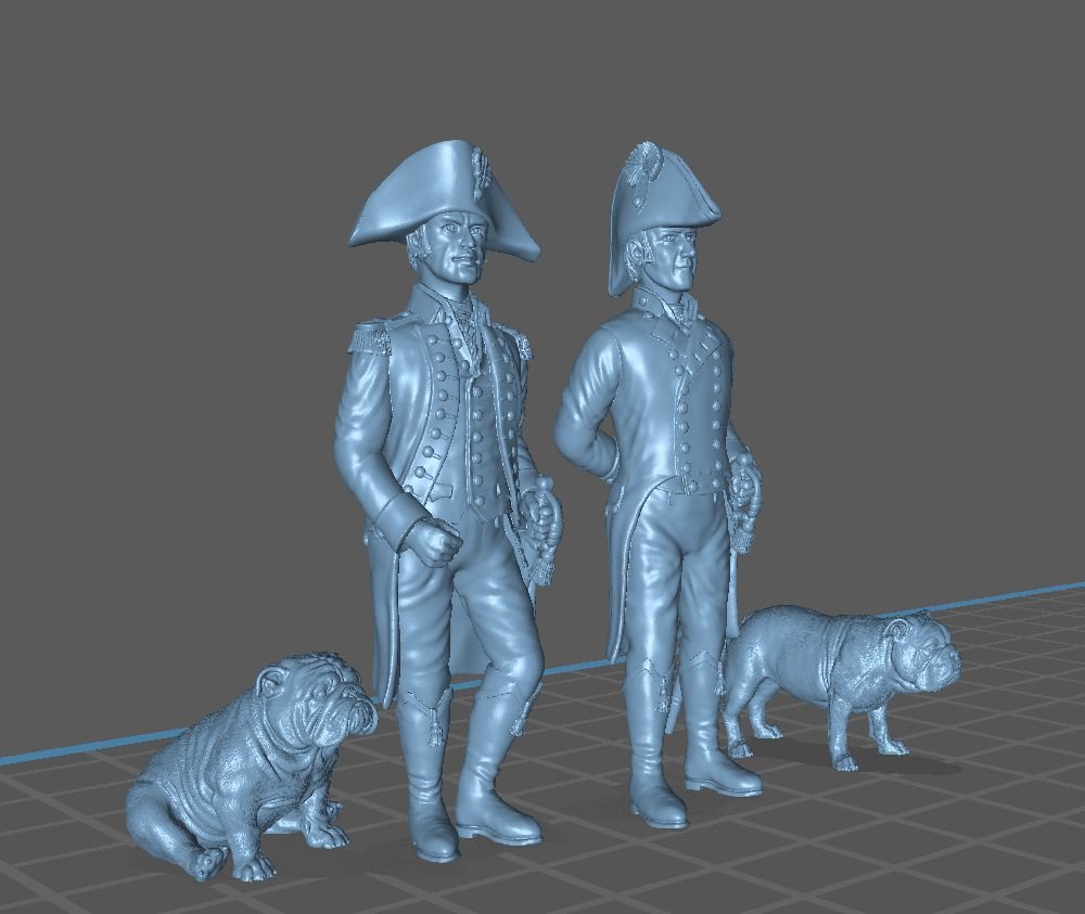
Its workshop weekend at Syren Ship Model Company!!! So not much inventory being made but it will be fun. A dozen fellas over at the shop for a little model fun. If this interests anyone else close by, let me know and I can schedule more!!! Its cheap...free except for a small fee to cover breakfast and lunch. I am always opening up the shop for folks and thought I would ask for anyone close by. Todays workshop (completed and it was fun) ....Intensive Rope making...soup to nuts. 5 hours give or take with a break for lunch - Selecting material (natural or synthetic) Not all cotton is the same...different results for different types of poly thread. Some poly looks too plastic and shiny and slippery. Mara vs E-threads. Silk and linen too!!! 25 minutes - Selecting the right color...so important. 15 minutes - Basic rope making demo on Syren ropewalk. 3 strand, 4 strand, left and right hand twist. 1 hour - group rope making...get on the factory floor and make your own. 2 hour - How to make your own recipes so you have all the sizes you need for your models....lets make 5 five sizes (.008, .012, .018, .025 and .030 rope) - Using smaller size thread multiple strands vs large thread and less strands to make the same size rope (uh what?)...one just looks better. 30 minutes - Making small ropes vs large ropes and cables - Rope fuzz...yikes...how to get rid of it...NO BEESWAX PLEASE. 25 minutes - Working with your ropes after you make a bunch...gluing, serving/seizing, How to get it to hang naturally and shop storage....NO wrapping around those small cards please!!! 1 hour Tomorrows workshop... Introduction to Painting miniature figures....5 hours give or take with a break for lunch Get ready for painting miniatures for nautical scenes. Lets get started!!! It is important to use matte paints because a shiny finish will make any figure look like a toy. Use a wet palette. This will keep the paint from drying out while you are painting. Acrylics will dry on a palette quite quickly. If you have to remix a color, it will be difficult to get it exactly right. Having it on the wet palette means you don’t have to re-create a color. Acrylic paint will dry on your brush very quickly. It is important to clean your brush constantly. When paint dries on your brush it will spread your bristles and you’ll not be able to form a point. Dried paint will also contaminate the fresh paint you are applying. When you have finished rinsing your brush in the cleaning cup dry it on your paper towel. You should not see any of the color on the towel. If you do, clean it some more. Use 2 cups of water. One cup is for cleaning your brush, the other cup is for thinning the paint. If you use the same cup, the dirty water will contaminate your colors. Thin your paints before using them. It should take two or three coats to completely cover the primer. This will prevent brushstrokes and buildup in nooks and crannies. At this scale, and for these purposes, our basic goal will be to have three shades on every part of the figure. There will be a basic tone, a highlight tone, and a shadow tone. The general procedure is to apply the mid tone and then the shadows, and finally some highlights. The procedure will change a little bit when we are painting flesh. When painting the hands and face, we will start with a dark tone, go over with a medium tone and pick out highlights such as the nose, ears, forehead, and fingers with the highlight tone.The highlights will appear where light is most direct on the figure and the shadows will be placed where light in general does not reach. At this scale, some exaggeration will produce a realistic effect. White and black are particularly difficult to paint. There is very little pure white and very little pure black to be found in nature. Only use pure white for the very tiniest of highlights and pure black for the very deepest shadows. Do not attempt to paint eyes. Unless you are relatively close to a person, you will not see the white part of the eye. We will paint a shadow in the eye sockets, and then a lighter area in the deepest part of the socket, and then a dark dot to create the impression of an eye. This will look quite convincing. The brass buttons, ribbon on the hat and hilt of the officers sword will be painted with brown, yellow, and white to create the impression of shiny metal. I will also bring some brass paint for those who don’t like that effect. This is meant as a starters guide. Everyone will find their own style and procedure. First attempts do not frequently result in a satisfactory product. Fortunately, acrylic paint comes off relatively easily with paint remover, and these figures do not suffer from this procedure if it is not applied too aggressively. (Yes, I’ve tried it.)
-

Mara thread - what colors do you use for fabricating ropes
Chuck replied to Sterling59's topic in Masting, rigging and sails
On the bright side though...One bobbin will literally last you forever. Get both the tan and the dark brown for serving and seizing and you will be set for life. Chuck -

Mara thread - what colors do you use for fabricating ropes
Chuck replied to Sterling59's topic in Masting, rigging and sails
Not in the USA...unfortunately. But these guys carry it along with even smaller stuff. UK distributor. Most are in Europe for the oddball sizes. https://www.williamgee.co.uk/product-tag/mara/ -
That is looking so good. You can instantly tell it is made with so much care with each piece.
- 968 replies
-
- hahn
- oliver cromwell
-
(and 1 more)
Tagged with:
-
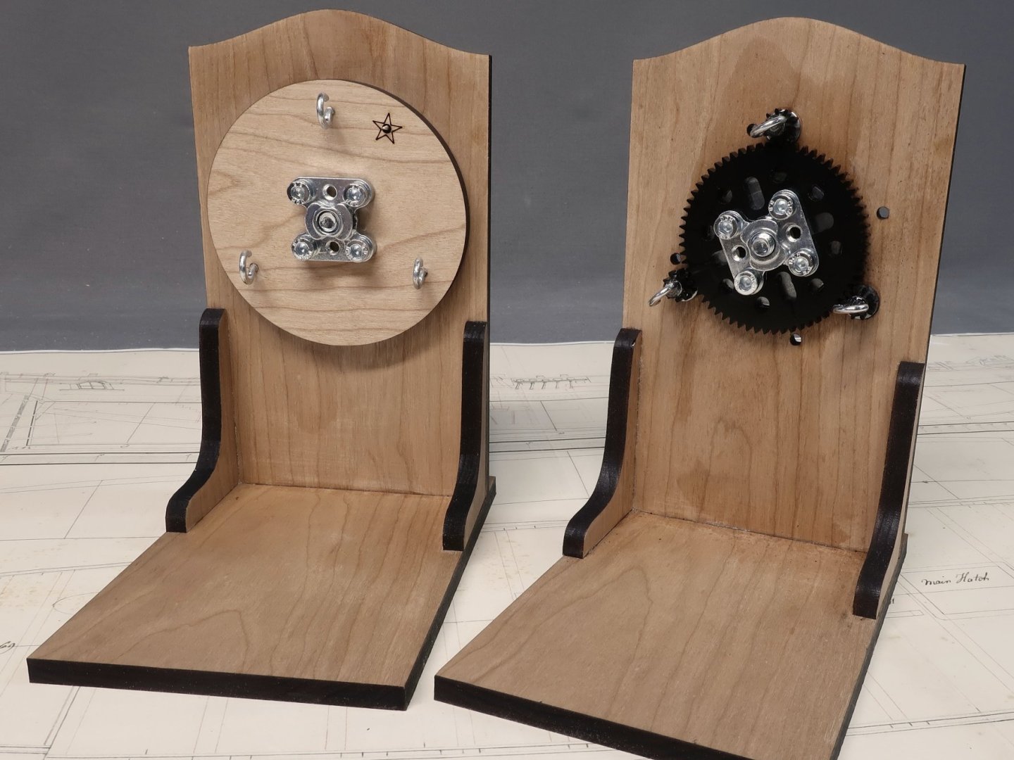
Just a heads up guys... I sold my last two rope walks today...at least for what I hope will be a short temporary hiccup. My supplier in Europe for the hubs, bearings and gears is temporarily halting shipments to the USA because of the T-Tariffs. I really dont want to spend the time to source new products in the USA and do a redesign just yet. This version works so well. I am hoping this situation will resolve itself in the short term and not be a 3 year halt on ropewalk availability. But who knows. If it seems like it is going to be a while, I will reconsider sourcing the items in the USA and doing a redesign. But unless someone magically started making this stuff in the USA over the last few months, its probably not gonna happen. My guess is that even if shipments resume soon, the price will be dramatically higher for these parts. Along with the Alaskan yellow cedar from Canada, these tariffs are making it hard to keep prices at Syren from increasing. But I promise I will try to keep prices the same for as long as I can...if I can even get the stuff that is.
-
Well so much for that idea. I have bought custom puzzles in the past. In fact I just ordered two for myself. But the prices are insane for 1000 piece puzzles of good quality. I think this is a dead idea....Oh well I tried. They want anywhere from $35 to $45 for each puzzle. Those that are reasonable have a 250 puzzle minimum for each design. So much for that idea...I should have checked first. Anyway, if folks are still interested they can contact me and I will email them the larger hi res image and you are welcome to order one on your own. I use Shutterfly or Ravensburger for my one-off puzzles. Sorry folks...everything is just so expensive these days. What a shame...I thought this could be a fun side project to offer folks. But at these prices, after shipping I would need to charge at least $55 to $60 per puzzle which is insane. Chuck
-
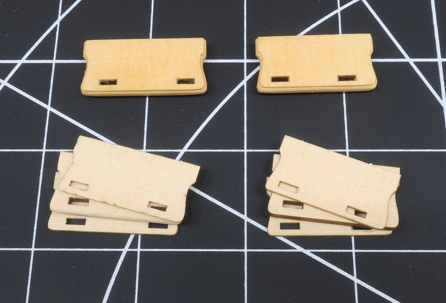
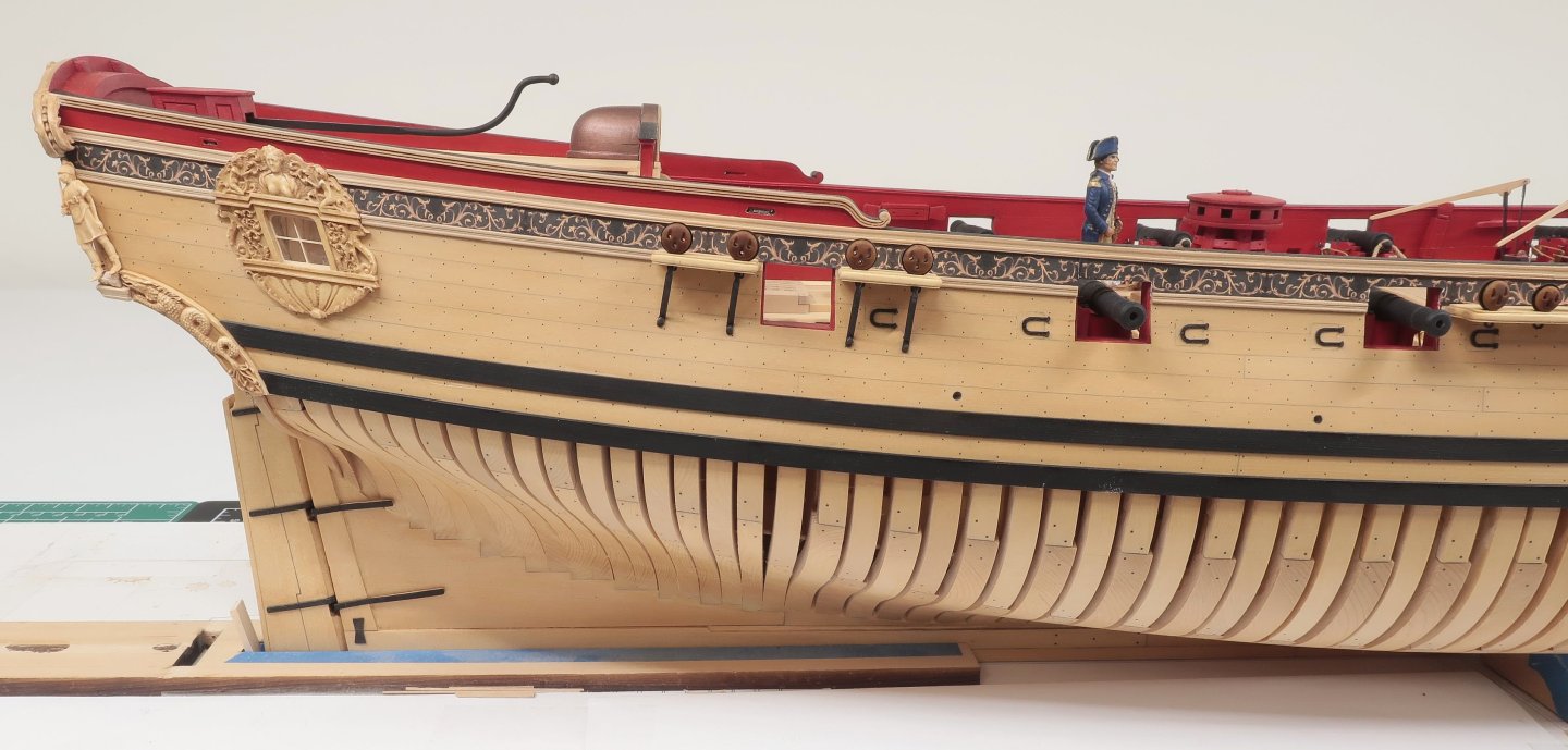
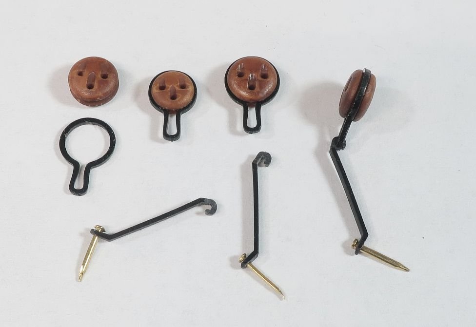
I started working on the channels and deadeyes today. Pretty straight forward stuff here. The channels are laser cut in 3 layers just like the Winchelsea model. The char was removed and the layers glued up. The outside layers are very thin but not thin enough for the final product. It is slightly smaller so after gluing it up, it creates a nice fancy edge. But you dont want the top and bottom layers too thick so they were sanded down even thinner. Almost card stock thickness. See the photo below. These do take a little time to complete but its worth it. I used spray mount glue to glue the thin outside layers in position. But I have also used a simple glue stick with success. They were glued to the hull as is usually done. The molding on the hull was carefully removed and the channels pinned into position with 24 gauge wire used as the pins. Then I did a quick test on the chainplates and deadeyes. I had already done this on the battle station mini kit so it was just a matter of repeating the process. There are two sizes of deadeyes. These are all 3d printed for you. The first thing you need to do is insert the deadeyes into their strops. The strops are laser cut for you out of plastic. It is quite easy to slip the deadeyes into the strop. The strop will flex so you can slip it right in. No glue is needed or soldering etc. Next you must prepare the deadeye straps. These are laser cut for you out of plastic as well. They have a pretty unique shape. But you will need to complete them before you can use them even though they are laser cut in profile. See the photo... The top of each strap has a “hook” of sorts on the end. This is hooked into the bottom of the deadeye strop after the deadeyes are inserted into the slots on the channel. But these “hooks” are too wide as laser cut. You will need to file them thinner in width so the hook will actually fit into the little loops of the deadeye strops. They start off as 1/16” wide…you will need to file them to 1/32” wide. File them a little on each side. Give it a test and see if the fit into the strop loop as you see it in the photo above. In addition, at the bottom of the chainplate strap a small brass nail secures it to the hull. You will need to drill a small hole thru the bottom of each strap for the little brass pins that come with the kit. Then I also rounded the bottom of the strap so it didn’t appear “square” at the very bottom edge. I used a #70 drill bit for the hole. This makes a big difference visually. So how do you add the deadeyes and straps on the model? You have two sizes of deadeyes which should already be stropped. Place the loop of the strop into the slots on the channel. You will see the loop stick out along the bottom of the channel. Use the plans to determine where the larger and smaller deadeyes go along the channel. Once the deadeyes are in the channel slots, the straps can be hooked into the loop under the channel. The straps are somewhat flexible. If one breaks there are plenty of extras. Use the plans to determine the angle of each strap along the hull. NOTE: there are two different lengths of straps as they are angled along the hull. The longer straps are used on the deadeyes on the aft side of the channels to keep the bottom of the chainplate straps lined up. It helps them line up better when pinned into the planking. Mark the locations for the brass pins on the hull using the plans as a guide. Pre-drill the holes for the brass pins. With the straps hanging from the deadeye strops, pin the bottom ends into the planking. I found it easier to cut the pins shorter because you don’t need them that long. Now to finish this off for all of the channels!!! I will post more pics when I finish it all up.
-
You can still go ahead and build them...No worries. You now know the situation. But no build logs here as it just encourages others to buy that stuff. Hayling is a pirated design and so is wolf....That same company UNICORN has a habit of doing so with all of their stuff. Wolf is just a badly converted wooden kit designed from the paper model plans. Even though you can buy them from third party sites they are all just drop shipped from China. Its a pretty common racket. I am sure you can start a log on other sites if you like but as I said, that just encourages others to buy them and some forums just do not care or they will insist that they are not ripp-offs just to make themselves feel better. My guess is that is where you heard about these two kits to begin with. I happen to know both legit manufactures and authors of those two who designed the originals for your ill-gotten kits. Sad to say...other sites just dont care since it doesnt hurt them, but it does indeed hurt folks. So best to check before you buy any new kits in the future. I hope to see you start a log here in the future of a legit kit. We have dozens and dozens of members who are in the same situation and dont care either way. They will build it on that other forum and just not start a log here on MSW...but most of them do it purposely without any remorse or thoughts about who it actually hurts. That is their choice. We see it every day. Our site sponsors arent very happy when we allow a pirated version of their product to be built here as a log....which makes sense. Again the other sites just dont care either way. But we do!!! Hope you understand. And yes you might hear from those other sites that the moment you buy one of these kits you are going to be banned and blacklisted from MSW yourself. That is just nonsense. We have never done that and will never do that. The only time we have asked someone to leave is when they refused to respect our wishes not to promote that stuff and insist on being able to post it here. So go ahead and build them and enjoy them. And we will welcome your next build log when you start it from a kit that is not on the banned list. Happy Modeling!! Chuck
-
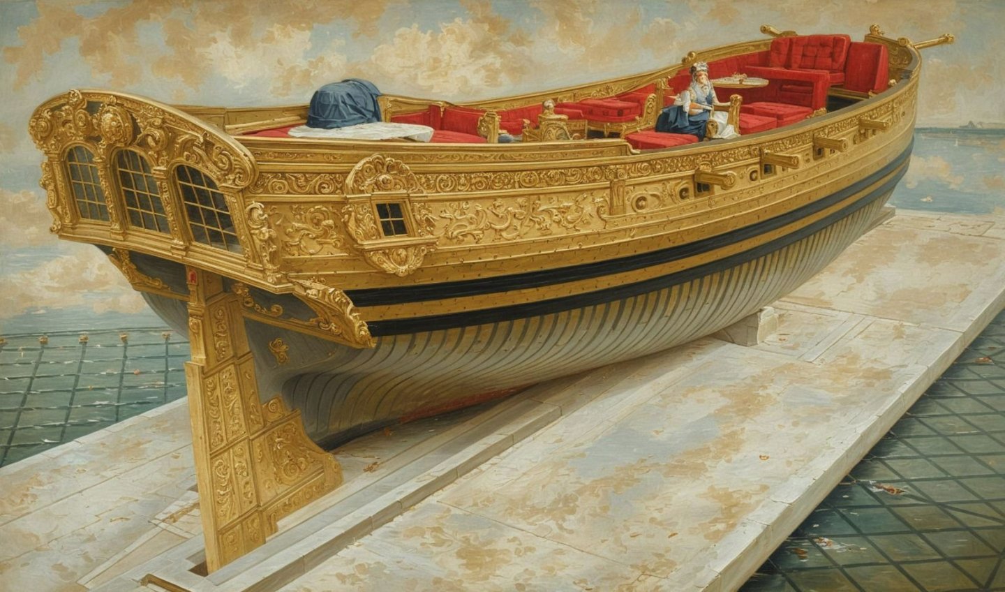
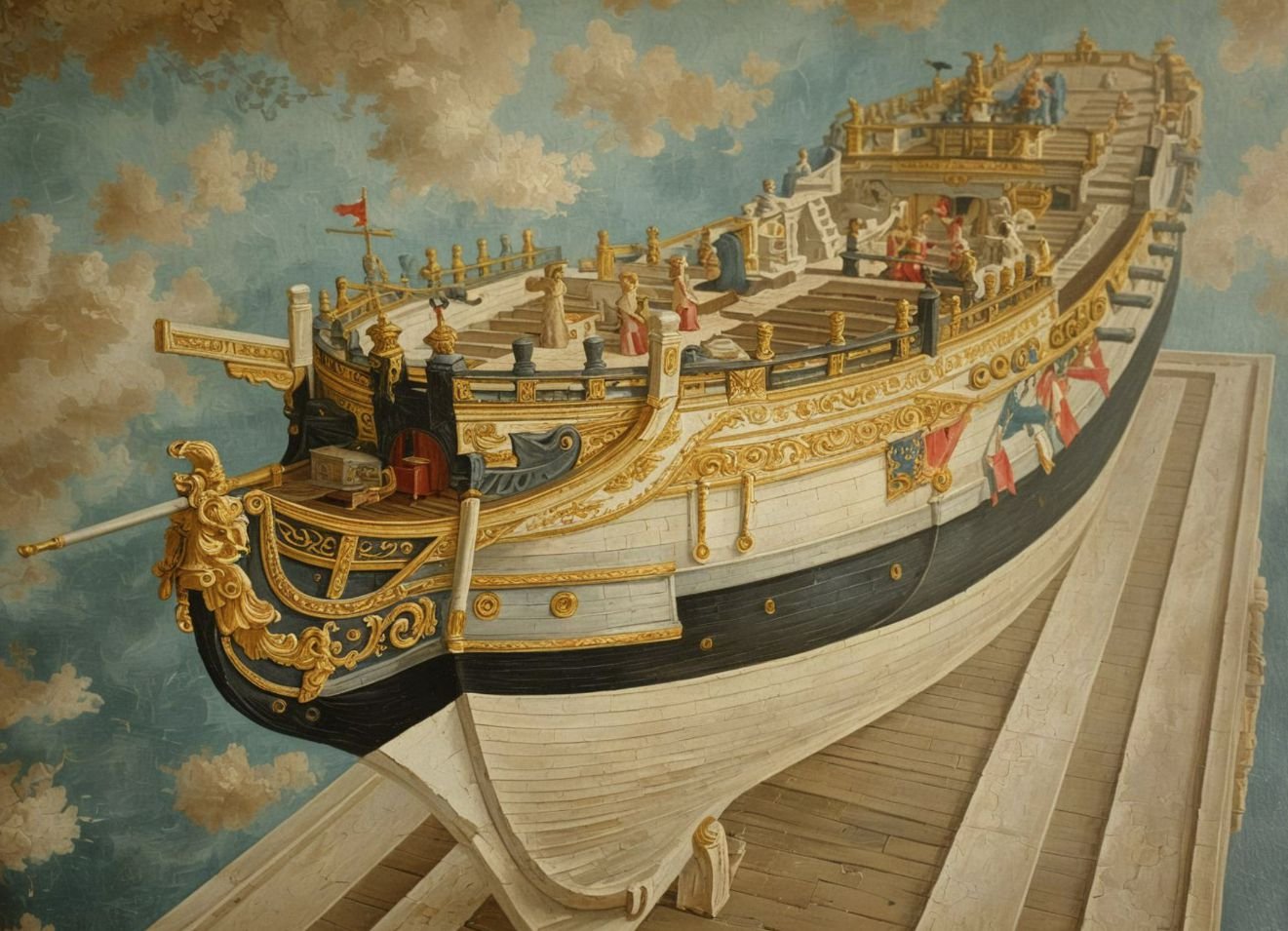
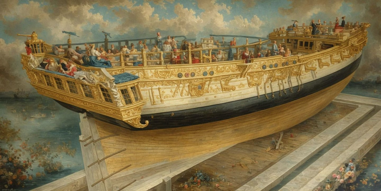
Coming soon MAYBE??? I was looking for a nautical puzzle that was interesting and colorful and there just isnt much out there. Soooo.... 500 piece and 1000 piece jigsaw puzzles of ship models/Ships like this. They are very fanciful and all in this style. Very whimsical Dali-esque indeed. Since they are somewhat expensive to produce I figured I would gauge how much interest is out there. The second image is actually my Winnie model but as you guessed it made into a fantasy image...very puzzle like as you would want and expect. I have this image on order for myself but thought maybe to produce others if you guys are puzzlers.
-

Mara thread - what colors do you use for fabricating ropes
Chuck replied to Sterling59's topic in Masting, rigging and sails
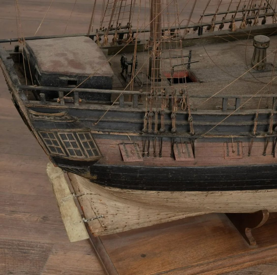
I agree with you...its just a model convention. I like the way it look as well. I do also like the look using historically correct colors too. But again, its just an artists approach. I do however think Henry Culvers knew what he was doing. This seemed to be a very popular rigging style in the heyday of ship modeling from 1880 to 1930ish. Check out the fine auctions currently being held. A French model of Sirene made in France in 1880...It actually looks much older. A steal at $14K. Minor restoration and cleaning needed, LOL. My wife would kill me. Why in Gods name would someone ruin this patina by painting the port lids such a fresh bright red!!!!! That makes me hurt a little inside. https://www.chairish.com/product/21201899/large-ship-model-of-la-sirene-with-cannons-and-mermaid-masthead-france-circa-1880 -

Mara thread - what colors do you use for fabricating ropes
Chuck replied to Sterling59's topic in Masting, rigging and sails
Not to throw a monkey wrench in this discussion...but as a devoted student of studying contemporary models, I noted that many of them if not most of them used Tan rope exclusively. No brown or black for standing rigging. Now this could be early restoration work that was the "model style" in the early 1900's but it does give a model an interesting look however inaccurate to history it may be. Additionally, I have also seen contemporary models with original rigging that are exclusively rigged with "hemp" colored tan rope as well. So it adds another possibility. Dont put yourself in the usual "box" of what is popular today or expected of you. Think outside of the box and the results might just surprise you. Its no different than planking with pear below the wales and boxwood above them. Its just a visual style. I know that Culver was partial to this style and the vast majority of models at the USNA he worked on are rigged in this way. I have long wanted to try this and still might do so on a future project. Its quite interesting to me. I am contemplating this very choice for my Speedwell at this very moment. I am curious what a modern model would look like with such a rig. -
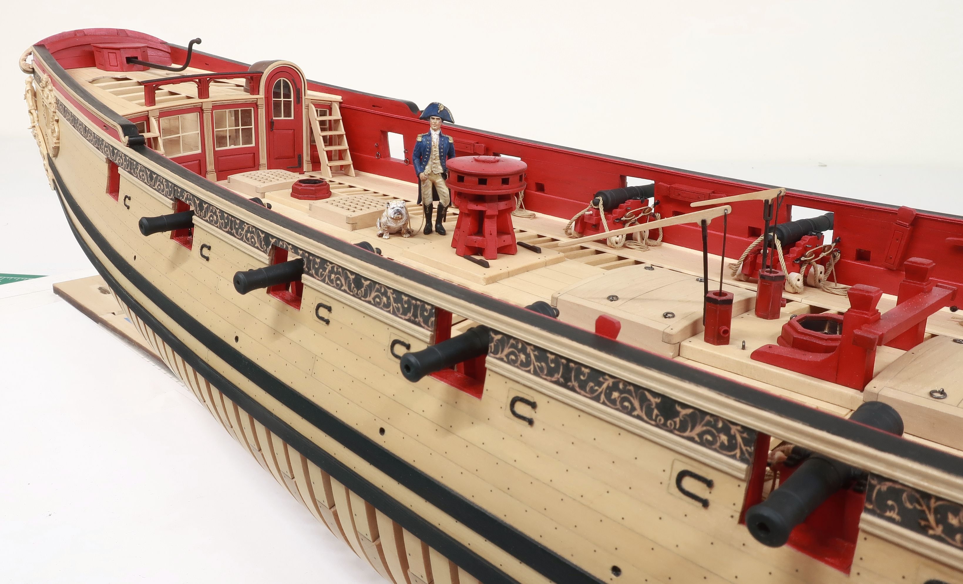
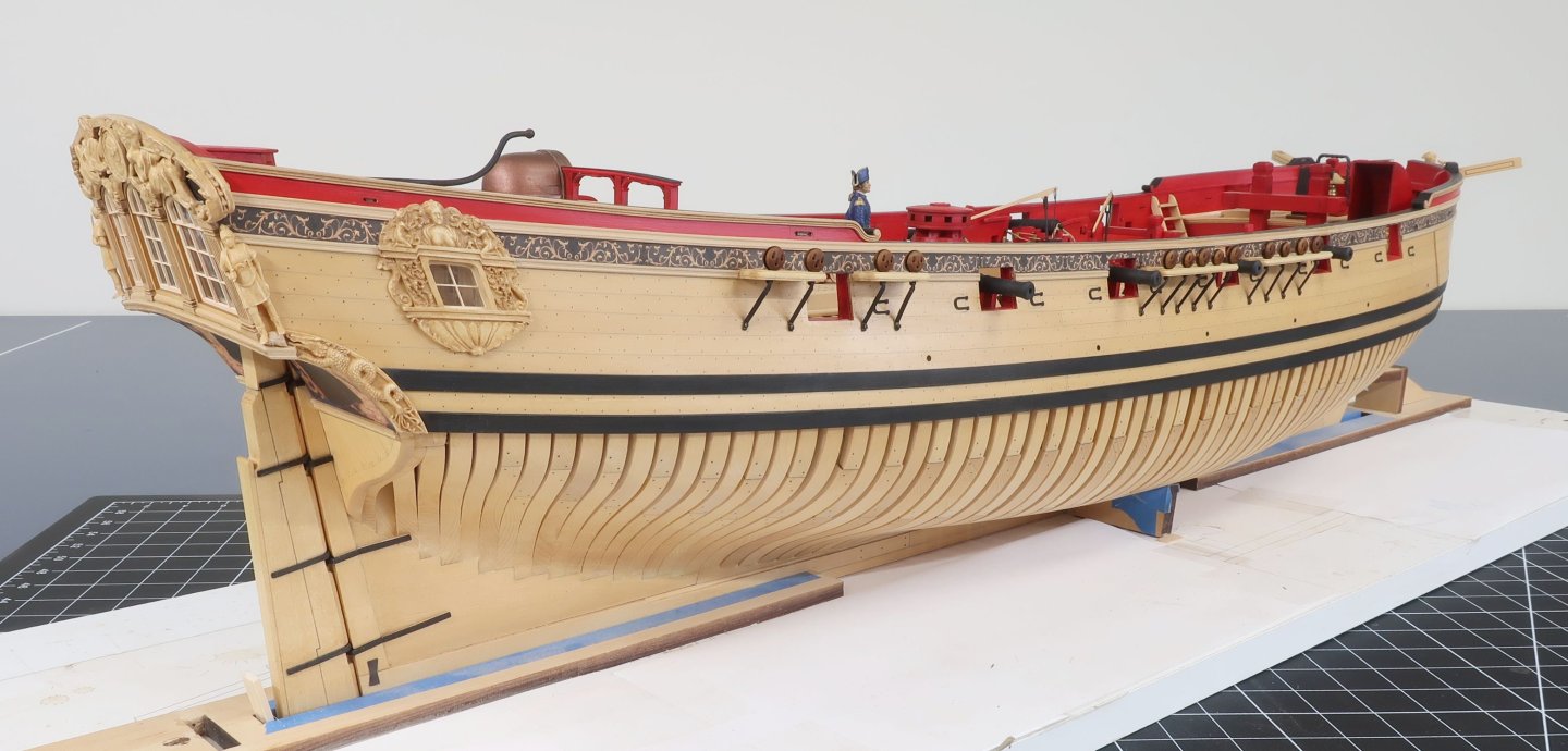
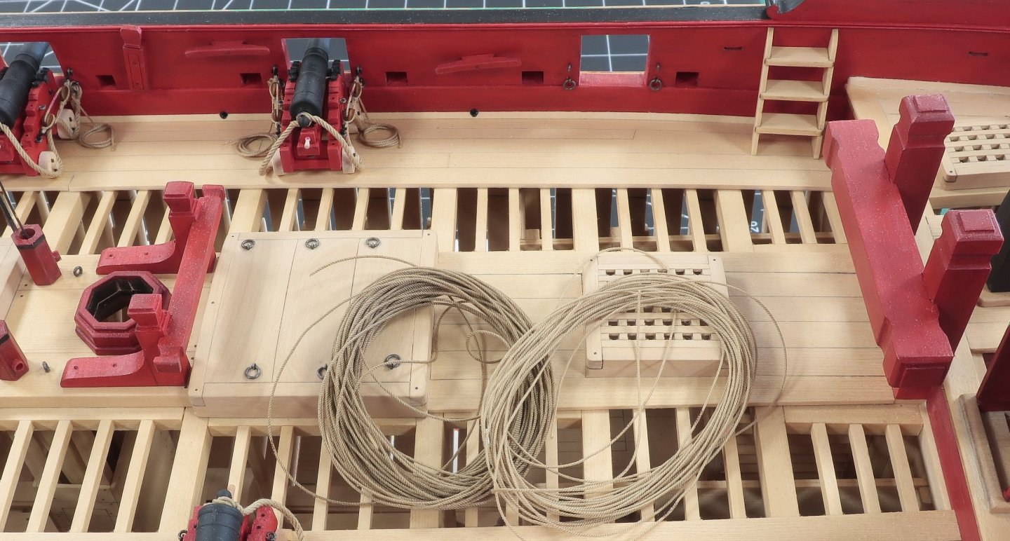
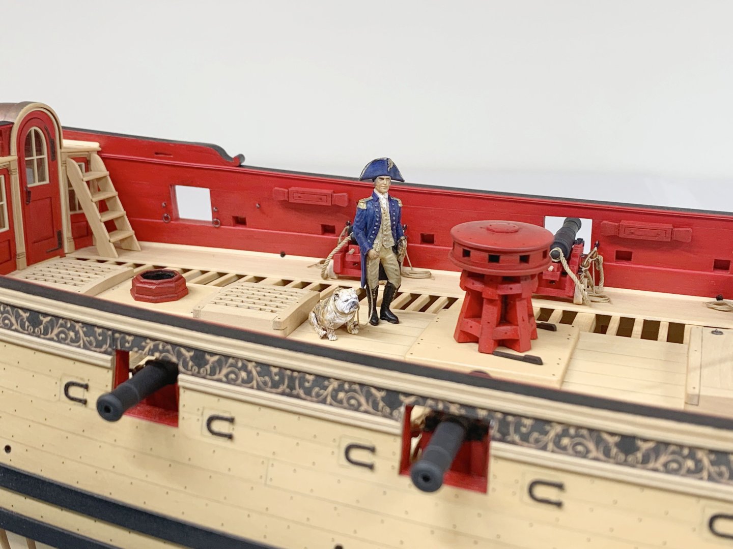
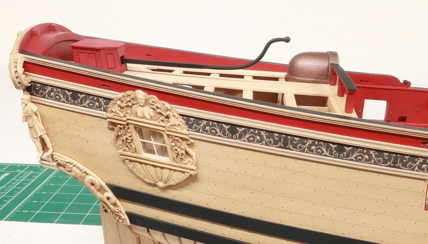
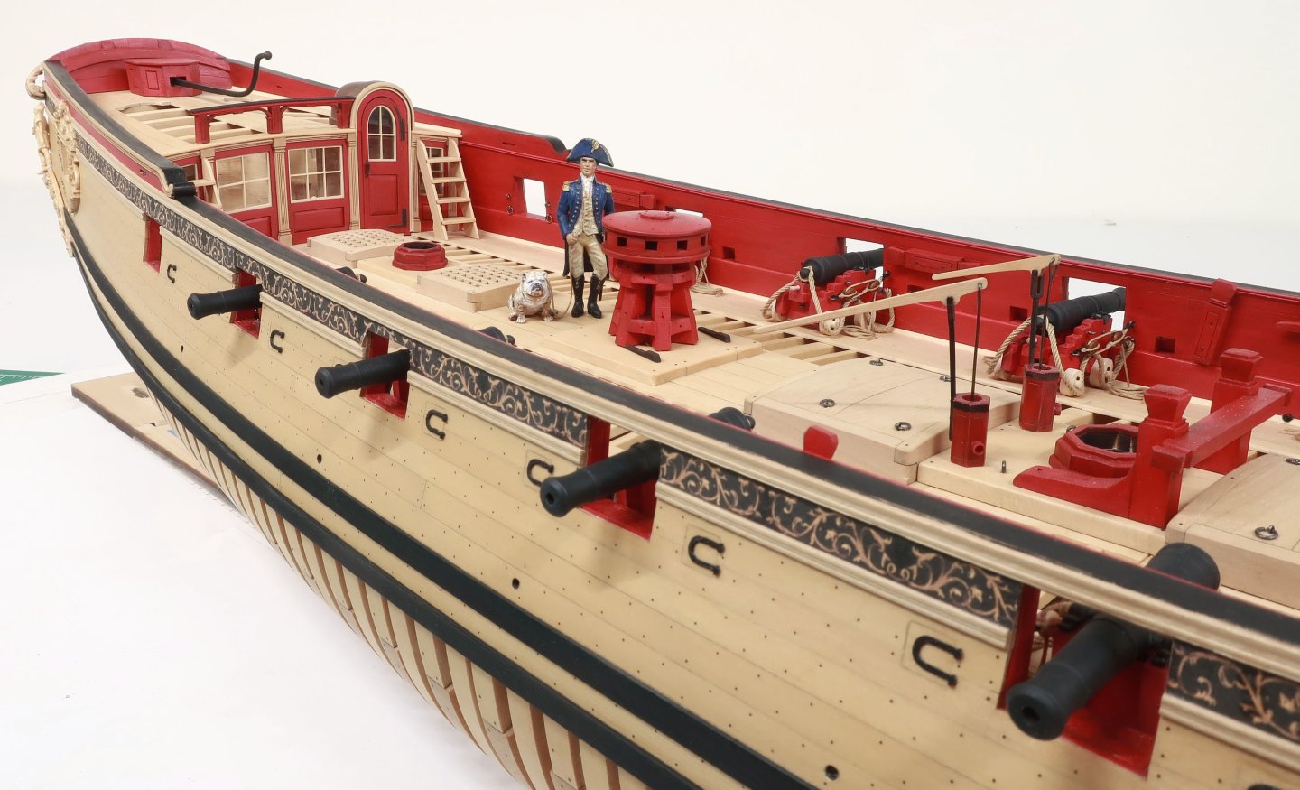
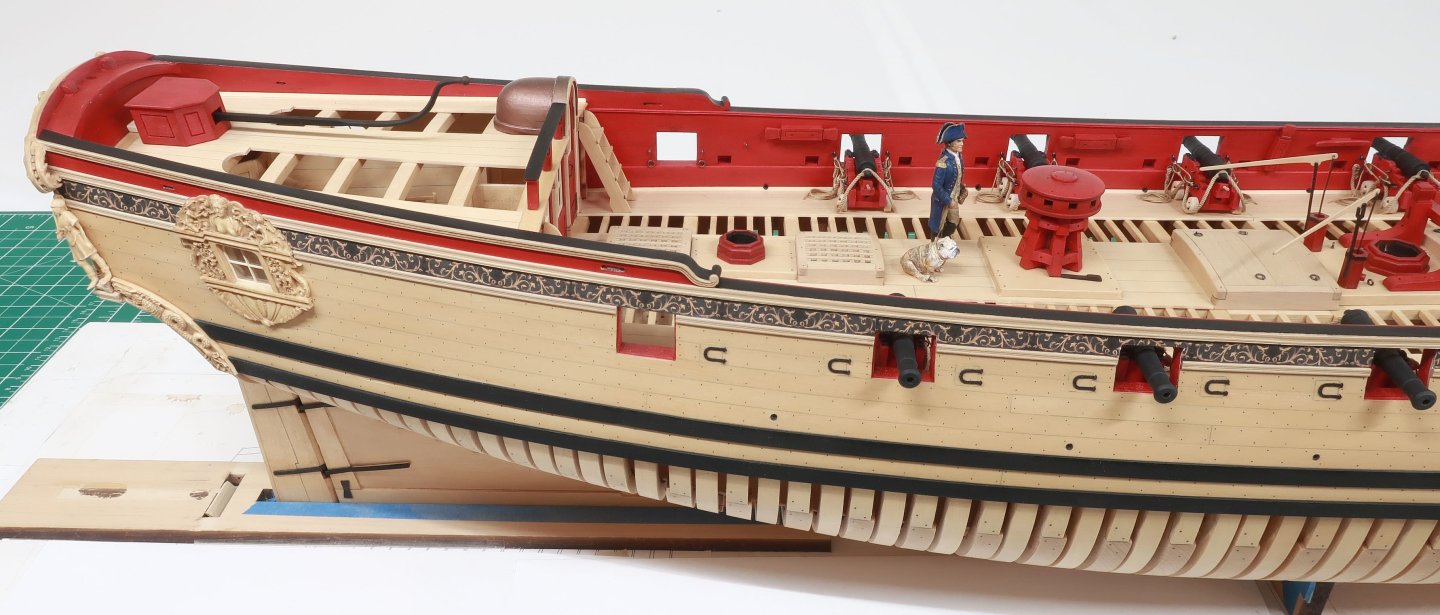
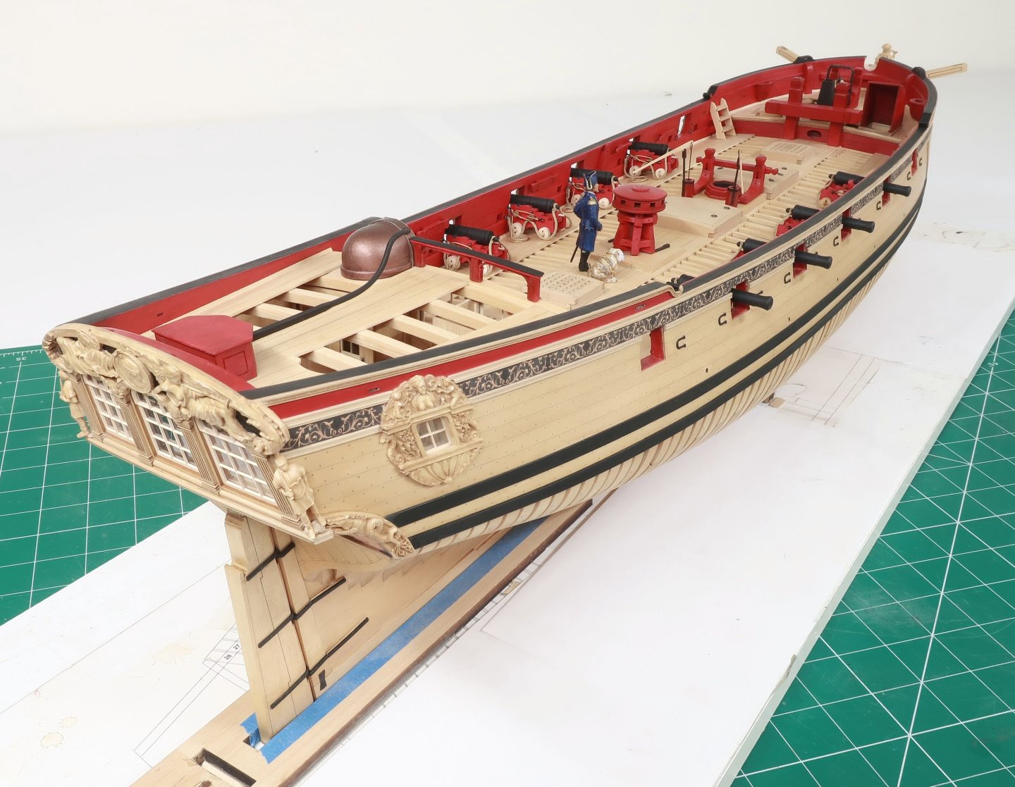
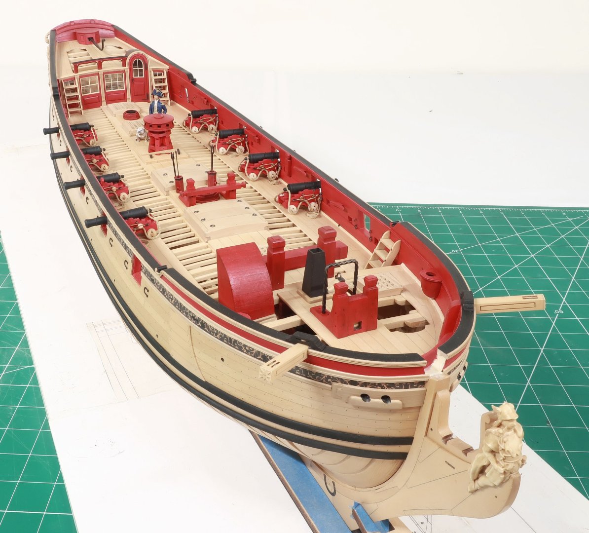
Here are some better pics....the last one was just on my phone. I wasnt just painting figures today, I also finished up the tiller. I was going to do a mash-up with metal and mixed media or even just make the tiller from all brass like Greg did. But that seemed a lot when I am awful at metal work. I also dont have those tools and havent soldered a thing in my life. So I said why not just 3D print the tiller. Its all painted black and many of you kit builders dont have the tools to do the metal work anyway. So the Tiller is 3D printed and all you have to do is paint it black which was done on the contemporary model...and glue it in position. I would say that it looks as it is supposed to and much better than if I fumbled through a soldering exercise. All of the deck-work and fittings are now done except for the binnacle. But next up is the remaining outboard hull details. Starting with the channels and deadeyes. But here are a few pics of the deck fittings all done including the tiller.
About us
Modelshipworld - Advancing Ship Modeling through Research
SSL Secured
Your security is important for us so this Website is SSL-Secured
NRG Mailing Address
Nautical Research Guild
237 South Lincoln Street
Westmont IL, 60559-1917
Model Ship World ® and the MSW logo are Registered Trademarks, and belong to the Nautical Research Guild (United States Patent and Trademark Office: No. 6,929,264 & No. 6,929,274, registered Dec. 20, 2022)
Helpful Links
About the NRG
If you enjoy building ship models that are historically accurate as well as beautiful, then The Nautical Research Guild (NRG) is just right for you.
The Guild is a non-profit educational organization whose mission is to “Advance Ship Modeling Through Research”. We provide support to our members in their efforts to raise the quality of their model ships.
The Nautical Research Guild has published our world-renowned quarterly magazine, The Nautical Research Journal, since 1955. The pages of the Journal are full of articles by accomplished ship modelers who show you how they create those exquisite details on their models, and by maritime historians who show you the correct details to build. The Journal is available in both print and digital editions. Go to the NRG web site (www.thenrg.org) to download a complimentary digital copy of the Journal. The NRG also publishes plan sets, books and compilations of back issues of the Journal and the former Ships in Scale and Model Ship Builder magazines.

