HOLIDAY DONATION DRIVE - SUPPORT MSW - DO YOUR PART TO KEEP THIS GREAT FORUM GOING! (Only 24 donations so far out of 49,000 members - C'mon guys!)
×


Chuck
-
Posts
9,660 -
Joined
-
Last visited
Content Type
Profiles
Forums
Gallery
Events
Everything posted by Chuck
-
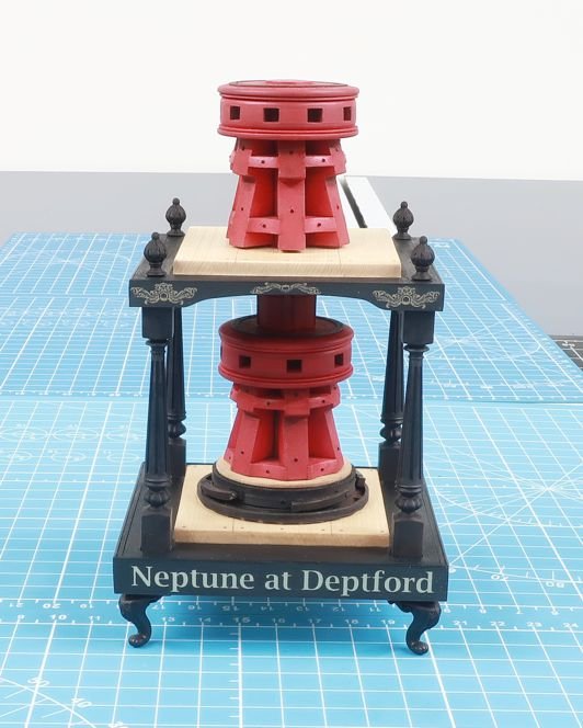
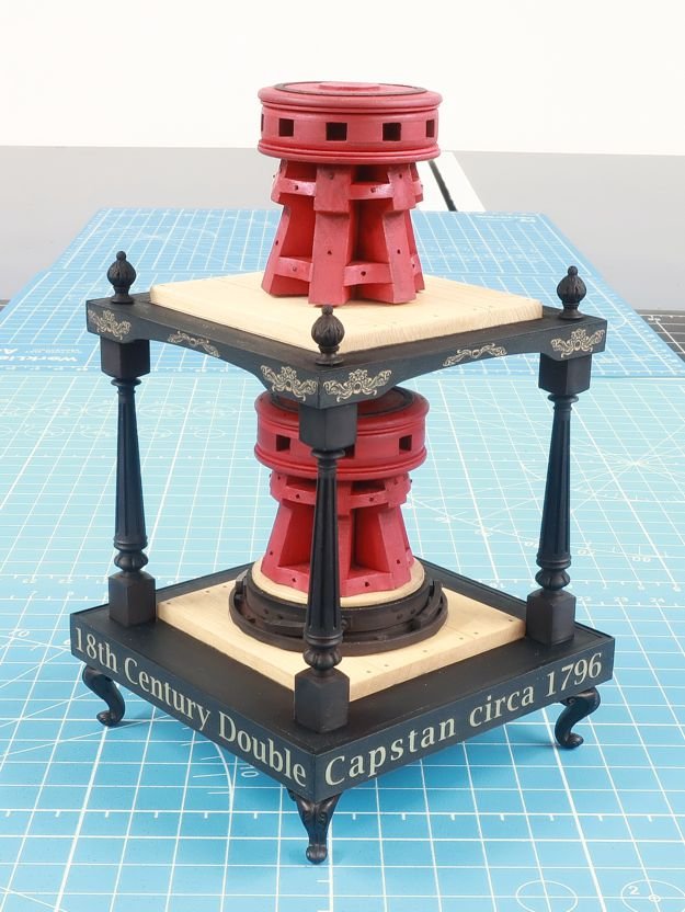
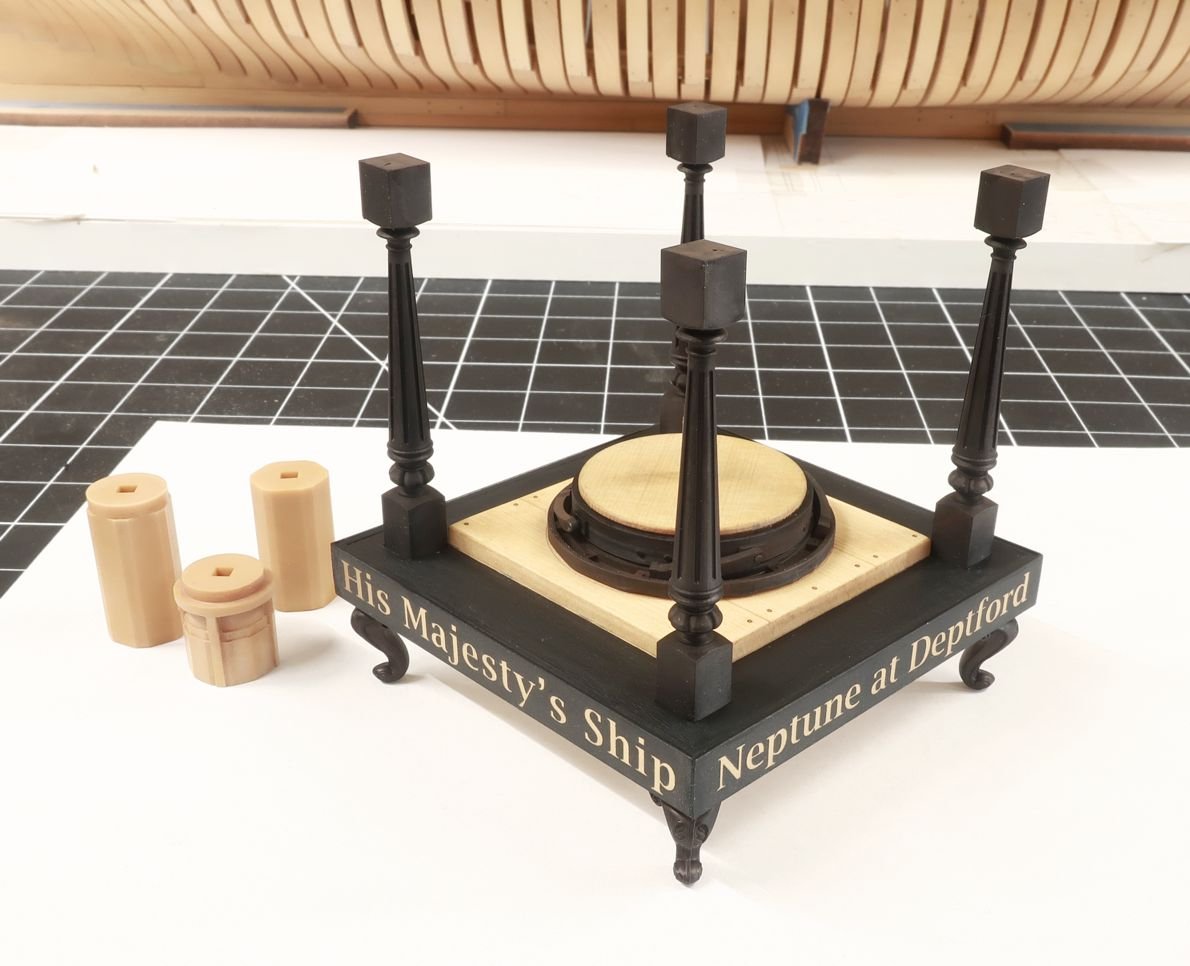
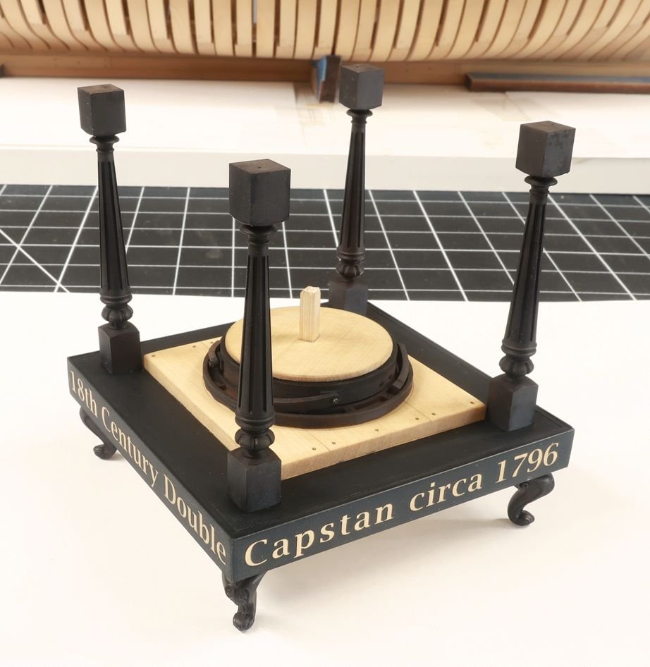
 Above you can see how I added the side letters all around the base. This is laser engraved on very thin plastic sheets. They are self adhesive. So just peel off the backing and stick them to each side. Remember to use the correct order so it makes sense when you turn the base. Place the panels on two opposite sides first. They are cut slightly longer than need so you can trim the ends flush with the base. Then repeat with the remaining opposite sides. Place them right on top of the wood lettering if you prefer this finish. Try and avoid sanding the gold letters with any abrasive. You want them nice and crisp and shiny. You can however sand the black underlayer. Try and get nice clean corners. Then paint the top of the base black as well with acrylic paint. I also applied a Wipe on Poly finish to the capstan partners. Chuck
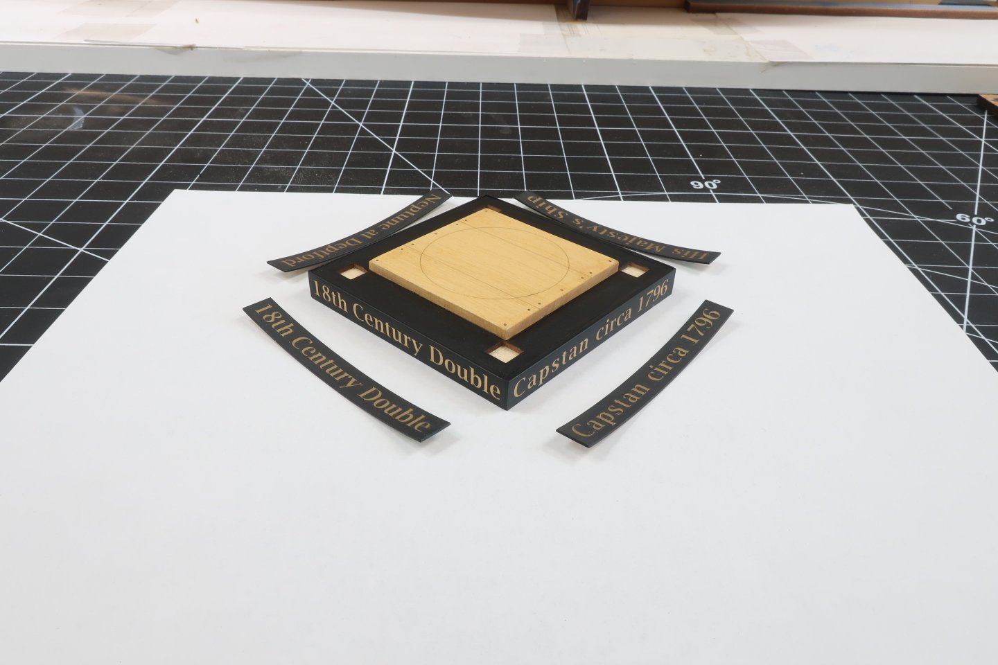
-
Well when the time comes maybe someone will produce them in that scale. But my kit making days are over beyond keeping up with those already on the market for folks still building them. As mentioned I am paying it forward and I am sure someone will produce these small projects. Chuck
-
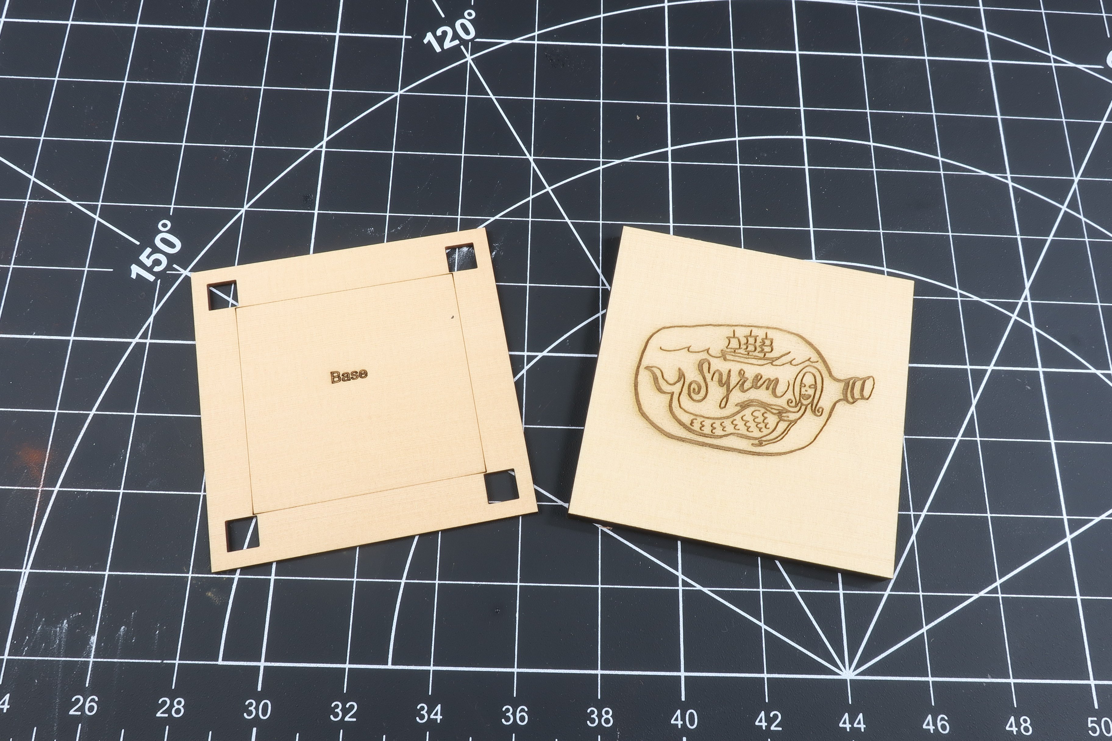
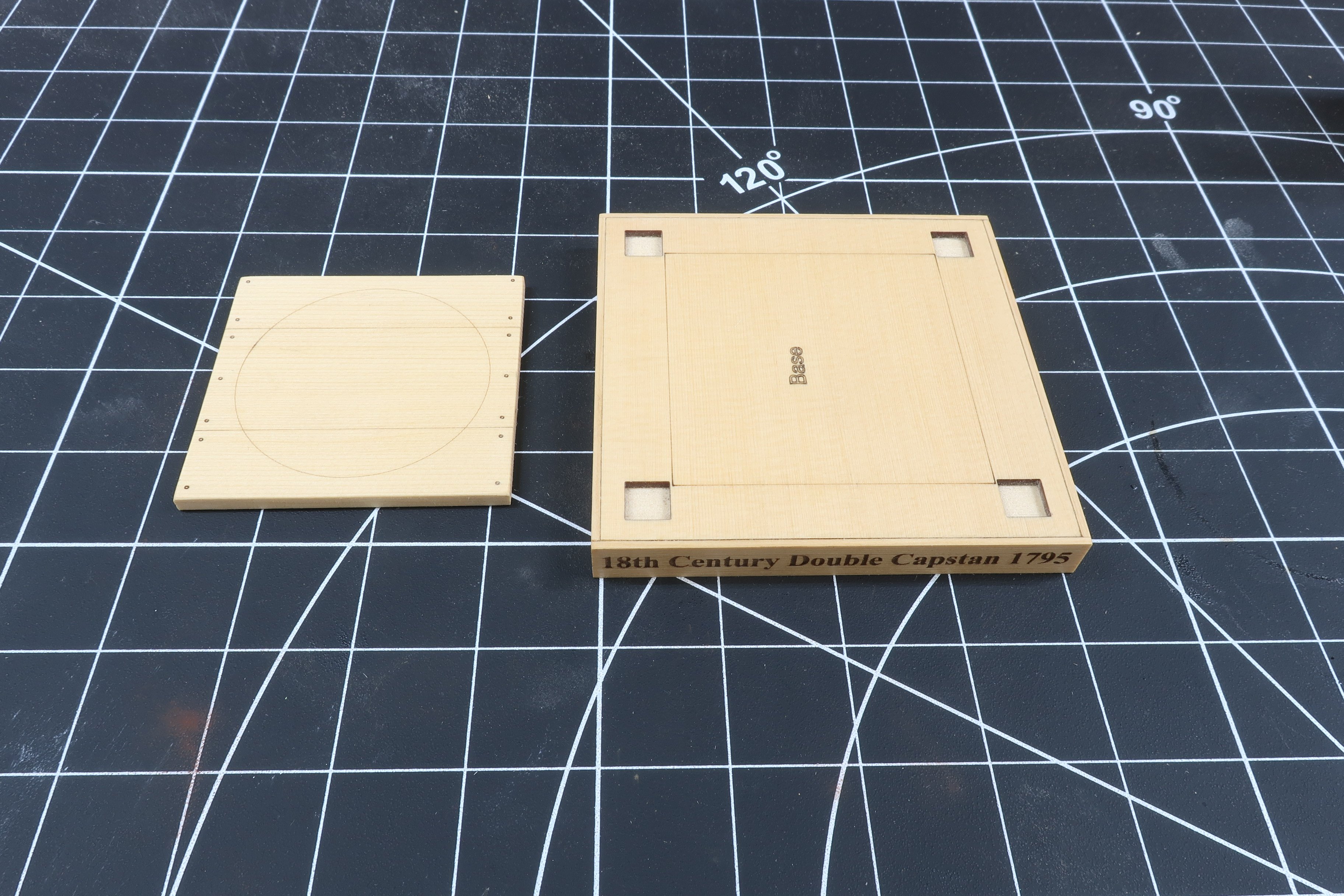
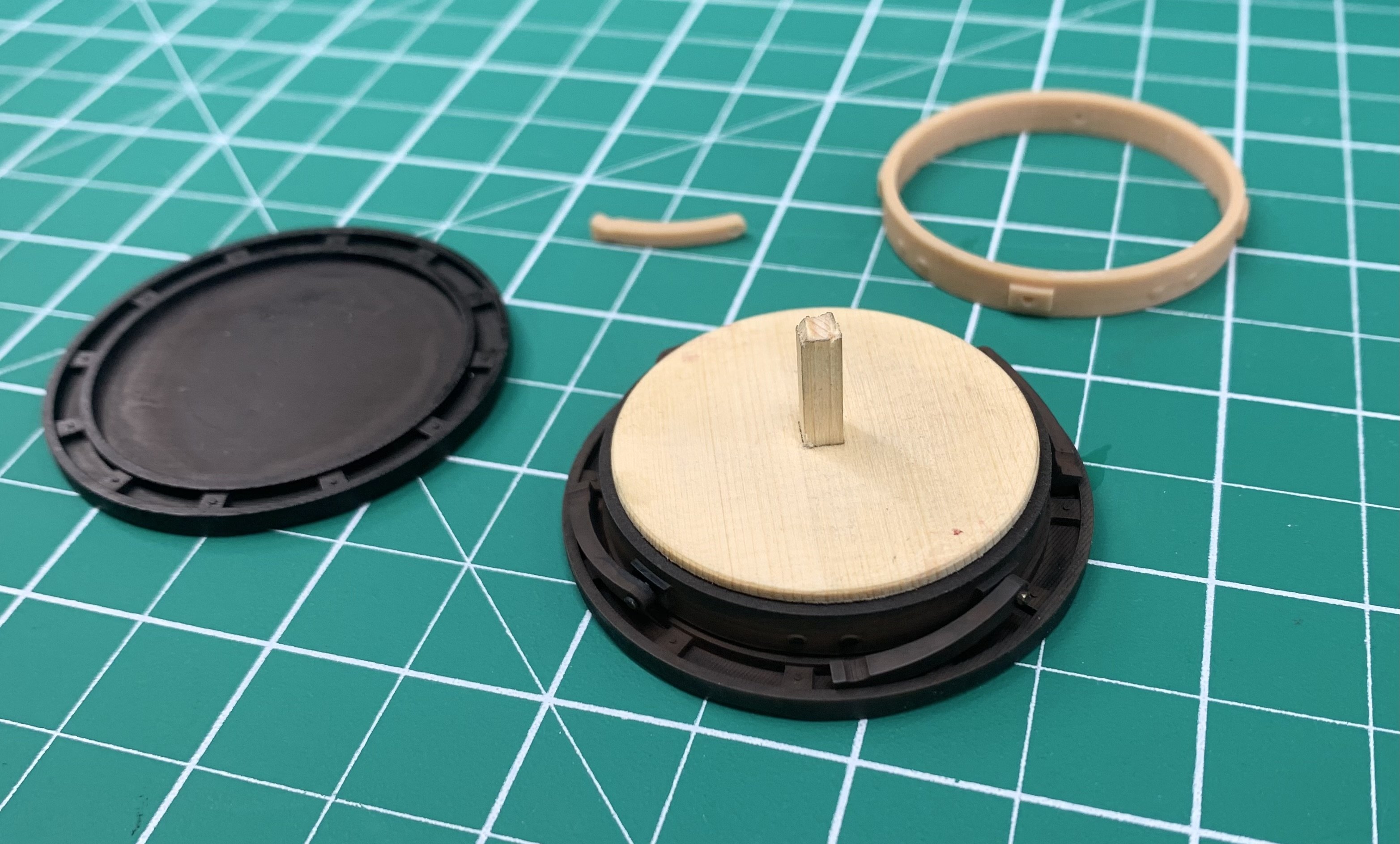
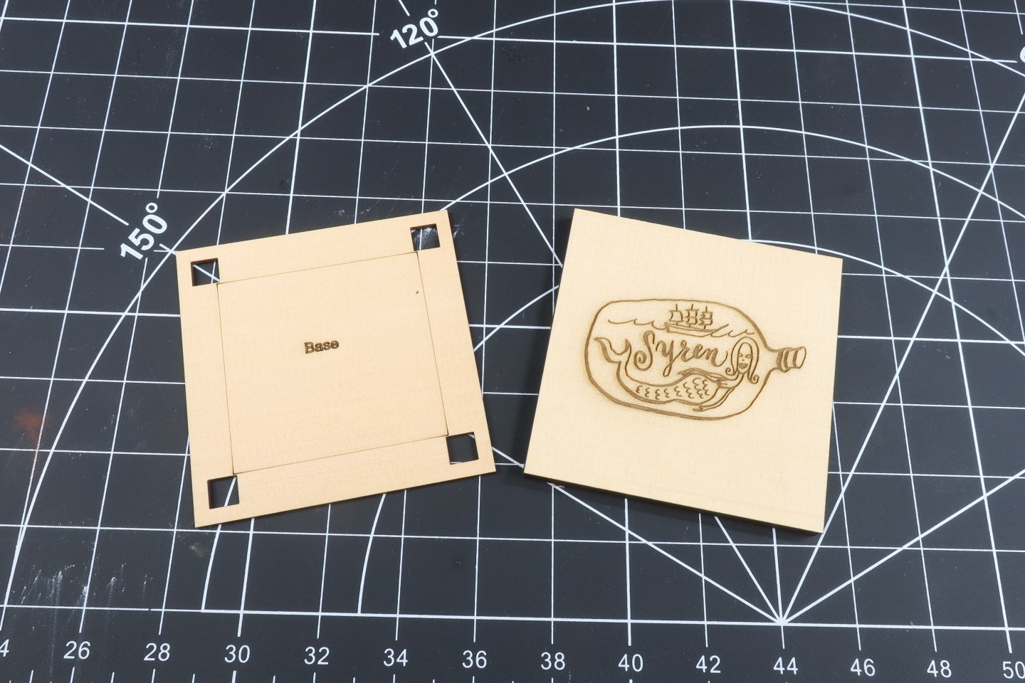
Before we even start making sawdust allow me to offer up some advice. For any of of you who have known me for any length of time, the two most important things to remember when building any model are....and they should be carved onto my tombstone. 1. SLOW DOWN...It always amazes me how folks just rush through each and every step. It is not a race. You dont get extra points if you finish first. Its the opposite actually. I have taught workshops and studied many build logs from folks at all levels of experience. Some of these guys just rush through the projects and I end up seeing glue joints with big spaces and gaps, way too much laser char on everything, and surface qualities that would defy expectations with glue globs everywhere. If folks would just slow down and enjoy it and complete each step as if it were a model unto itself they would take their models from a 5 to an 8 almost instantly. Just slow down. Appreciate every step in the process. 2. Use a light touch...we are building delicate and elegant works of art made from sometimes very thin and delicate parts. We are not carving a bear with a chainsaw. Handle your model and parts with care and keep your hands and fingers clean as you build. You will take your models from an 8 to a 10 in short order. To begin building the model, start with these two laser cut pieces for the bottom base. The part on the left is 1/16" thick and the one on the right is 1/4" thick. Depending on what wood you select (I am using Alasken Yellow Cedar) your laser settings for speed and power will vary. Most of this project has all of the wood parts painted. At least the version I chose to create. So you can use virtually any wood from Cedar to even basswood as it is readily available and easy to laser cut. But yes you can use Boxwood or Swiss Pear too. It just depends on if your laser cutter can cut through 1/4" thick material. That will be the thickest material we will be cutting and only a few parts including this base. The part on the left is actually upside down. Just shown so you can see the engraved logo I added which wont be seen unless you look under the base. This is the perfect area for you to add your name and the date you completed the model...hopefully you will also leave my Syren logo, LOL. Other parts will have laser etched lines like the part on the left. I will discuss my laser parameters more directly in the laser cutting tab and section of this group. As this is just the build log area let us continue. Glue the 1/16" thick piece directly on top of the thicker base part. Make sure your etched lines face up so you can see them. Also remember to adjust the direction of the grain so the layers are at 90 degree angles to each other on both layers for strength. The engraved logo of the bottom layer faces down. Also try not to have any glue squeeze into the small square slots where the 3d Printed columns will eventually sit. This will effect how they sit in those slots if there are glue blobs in those. Clean them out soon after applying the glue. There are also laser etched wooden sides that must be added and are laser cut from 3/64" thick material. You may opt for the Black and Gold sides instead but I know some folks like the natural wood look. Either way you must use the wood sides and the can be covered up with the black and gold pieces later. But for now just add these as the omission of these parts will effect how the black and gold versions will fit later on. Glue a section on opposite sides first and then glue the remaining two in position next with the top edge being flush with the top edge of the base. Clean off the laser char from the top and bottom edges first though. Above you can see the 1/8" thick base which can be glued in position next. It is the part marked LB-1. The LB stands for Lower Base. Unlike the base itself this is not a perfect square so it only fits in one direction and corresponds to the laser etched square on the top of the base. Clean of the laser char and light sand the top with some 320 grit paper to make it nice and smooth. I do this to all parts by the way to prepare for final finishing. In this case some satin wipe on poly. I also knocked off the top edge all around this piece that represents the capstan partners. You dont want a hard edge here. Just soften it up a little bit. You can the laser etched lines that represent the individual timbers and the bolts. You could always drill out the bolts and add some real or simulated versions if you like. It is up to you.


-
There are also plenty of 3D printed parts for this small model. Here is a look at them all in the chitbox slicer.

-
Even though this is a small project and model there are still quite a few parts to be laser cut as you can see below in this low res file.. We will discuss the color coding and techniques and materials I used later as the build log proceeds.

-
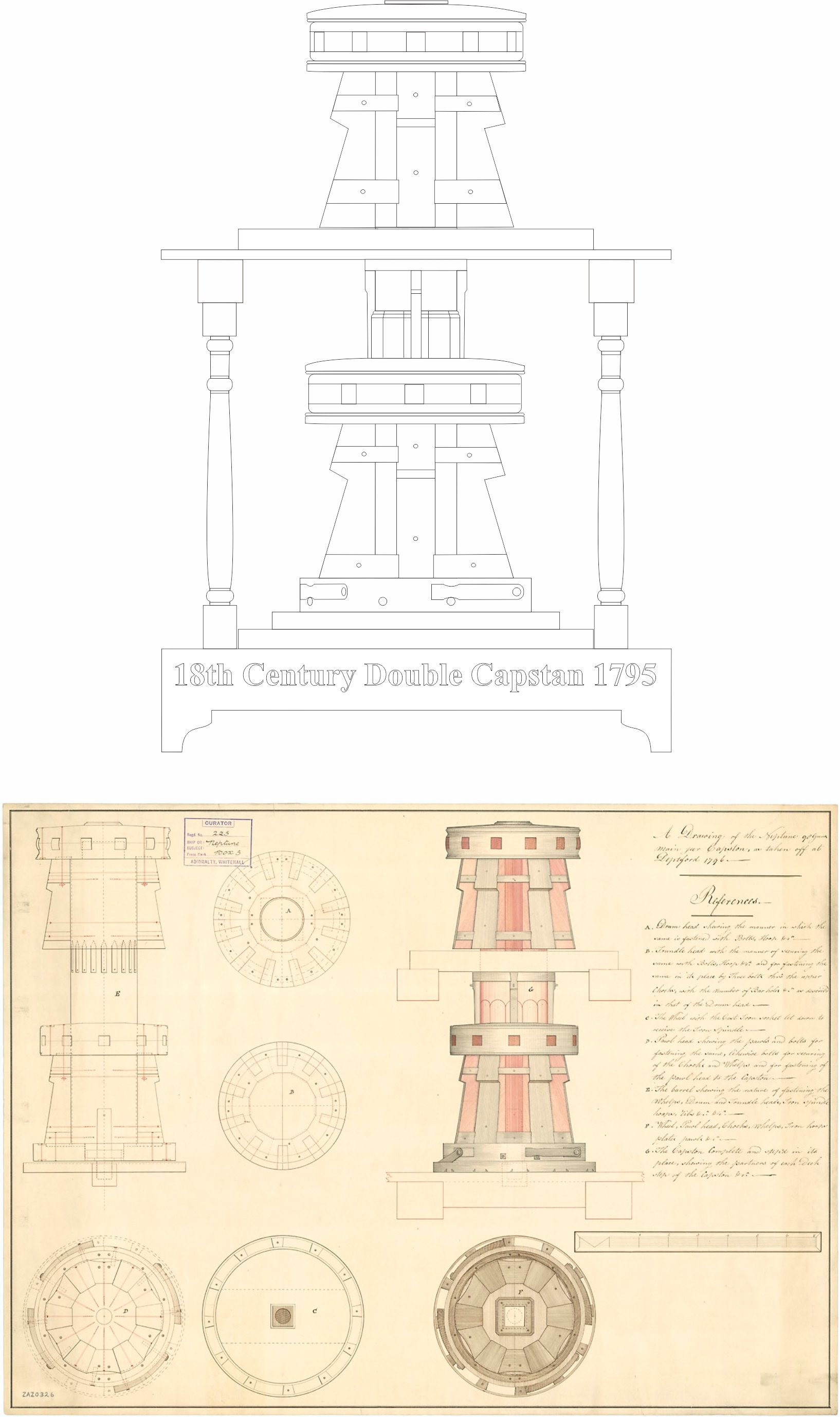
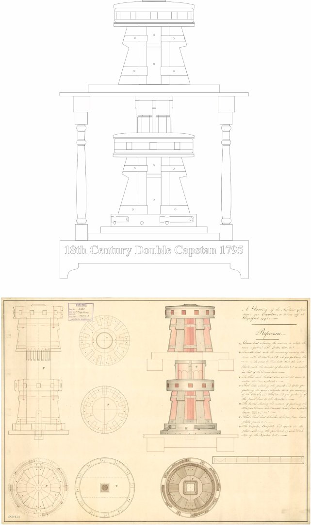
The plan sheet This is an plan overview to scale...which you can download. All other parts and files can be downloaded from their respective tabs at the top of this club page just below the banner photo for the group. Capstan project plan sheet.pdf

-
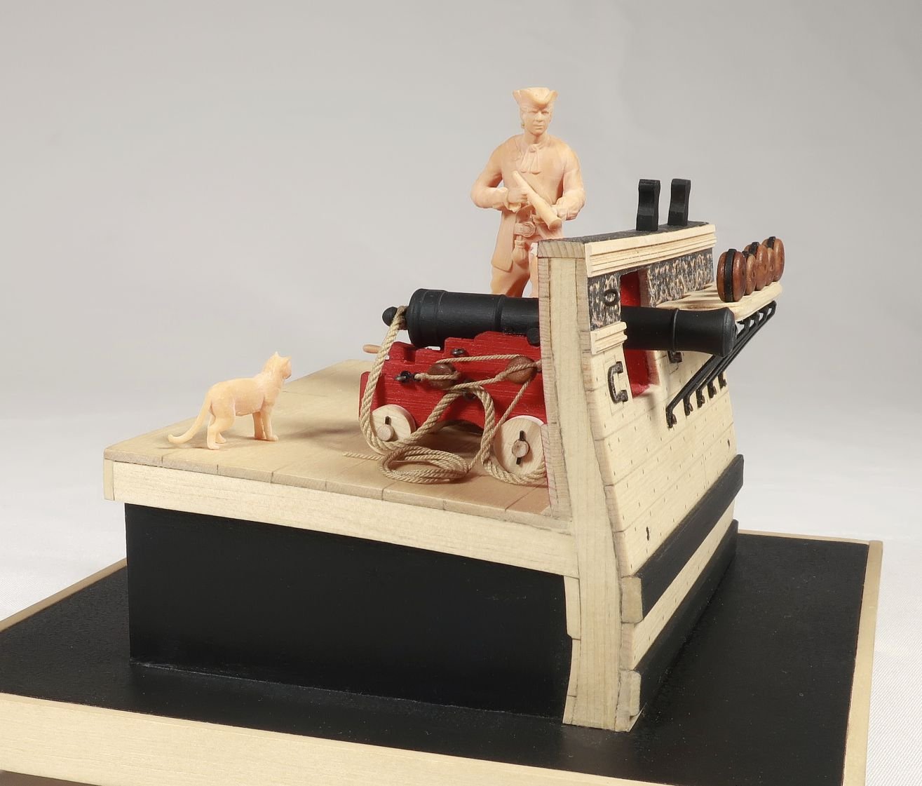
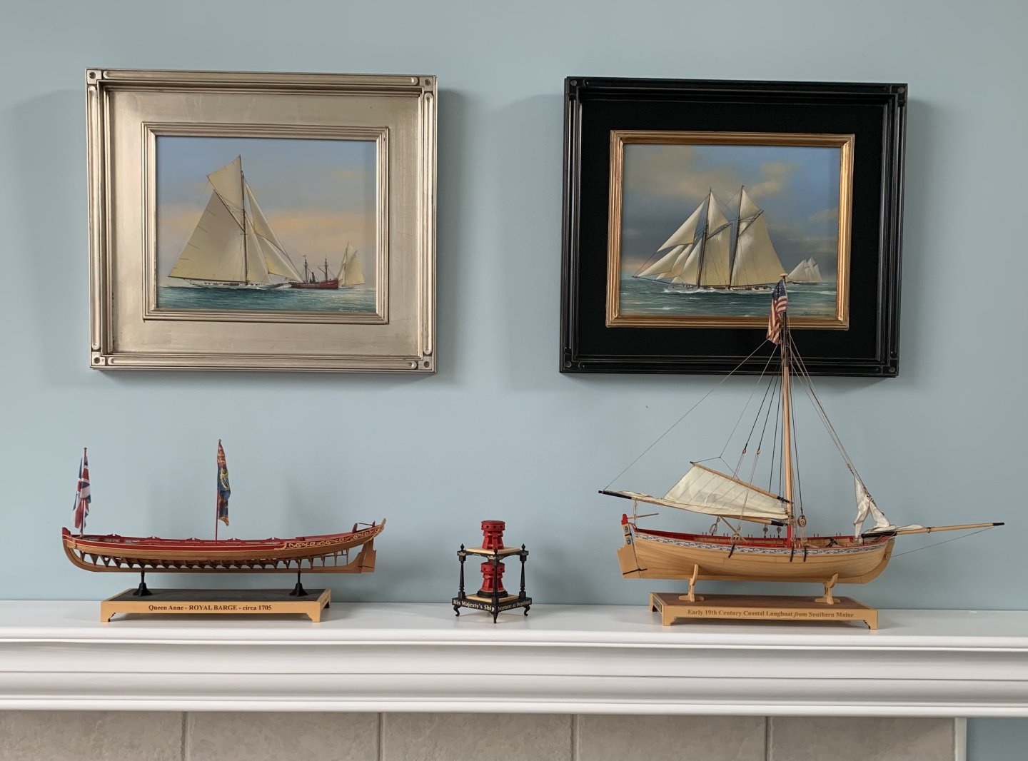
This project is primarily based upon the contemporary draft from the NMM for Neptune below. Some changes and additions were designed into the project from other sources but its a pretty close representation. This type of small project was a popular modeling subject back in the day. There are countless examples out there (including contemporary period models) and so I thought it would be a fun object to build. Here are some examples. The displayed varied and some were very decorative. Their size and scale varied as well. Our project will be made at 1/2" scale.


-
As many of you can see I am starting to create the area for the Capstan project... But do me a favor as it is a bit overwhelming. Please dont try and join yet. Please wait till I give the go ahead. Its tough enough to set this up without getting a barrage of requests from folks to join...and there is no content up there yet so its gonna be a while longer. Maybe a week or more to add the files and build log before I can start to accept members of the group. Thanks in advance. Chuck
-
This is my start of the Capstan Project prototype. This Log will be locked Initially so I can get all of the content up here for the entire project.... Folks can participate and ask questions in my log once I finish writing and creating all of the instructions.

-
Metallic paint questions....
Chuck replied to CPDDET's topic in Painting, finishing and weathering products and techniques
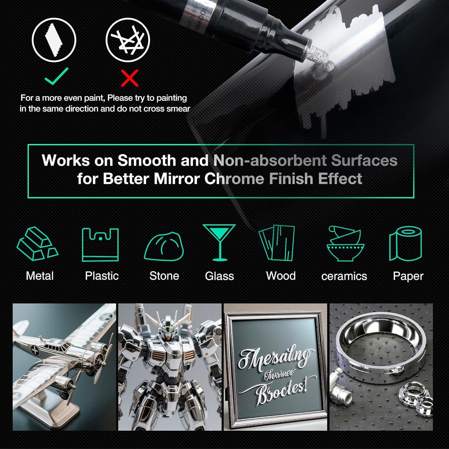
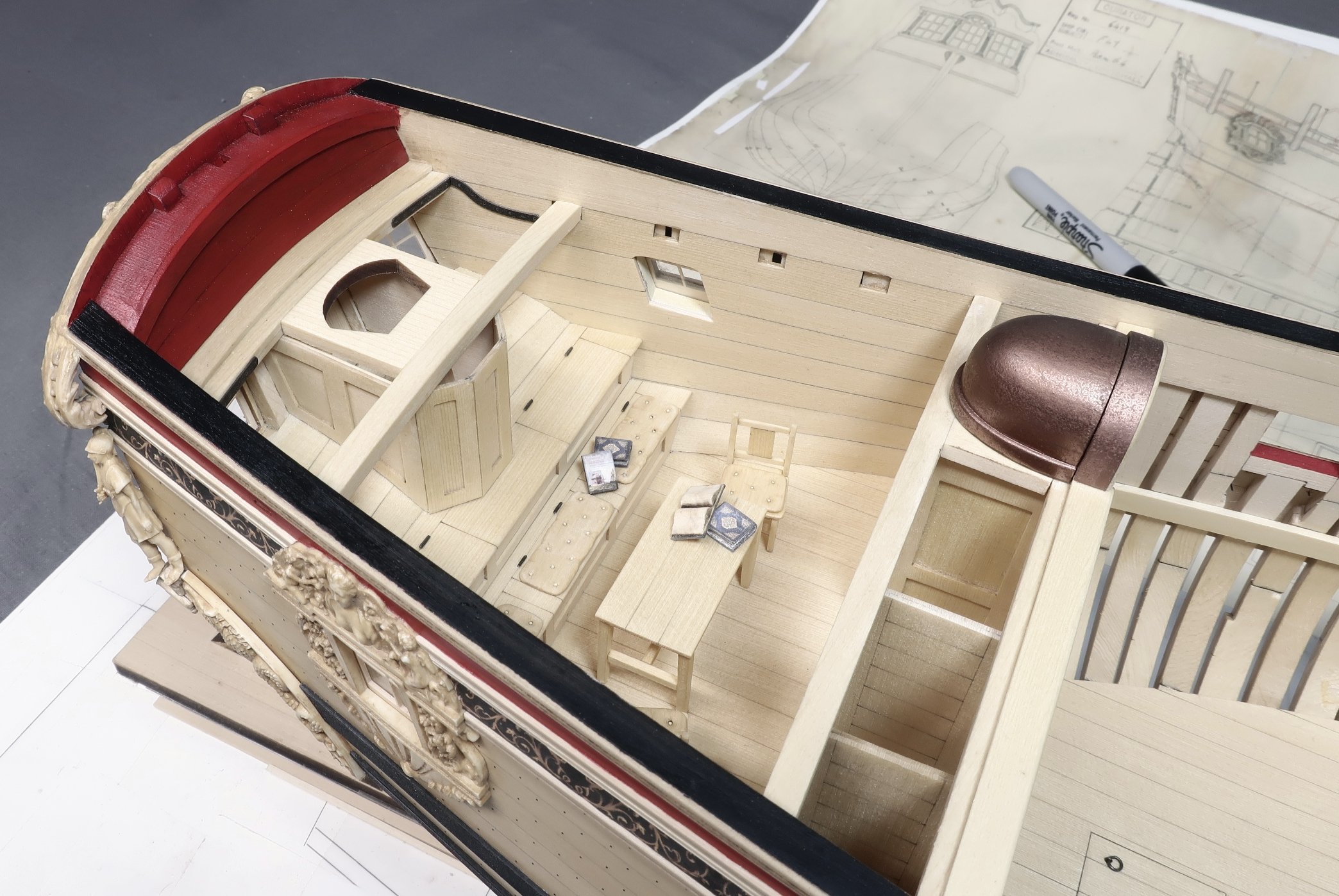
I have found that the paint markers available these days are excellent. I use these exclusively. I usually flow a puddle onto a small palette and use a brush to paint the surfaces. They work excellent. You can find Gold, aluminum, chrome, brass and copper etc. https://www.amazon.com/Markers-KERIFI-Reflective-Metallic-Permanent/dp/B09VXVYMF7?th=1 I used a copper color to paint the top of the cupola for my Speedwell. I didnt want super shiny so I buffed it after adding some light brown weathering powder.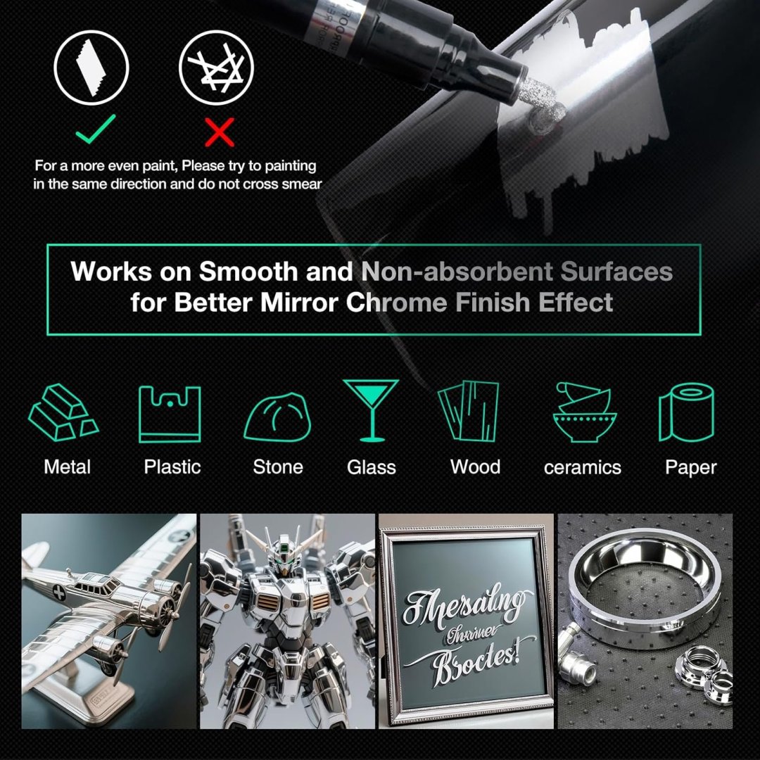

- 15 replies
-
- 13
-

-

-
Thanks Guys I am back in the shop after the wonderful workshop up in Niagara on the Lake. I will start creating the project for the Capstan model today but it will probably take me about a week to finish setting it all up. I havent had a chance to reach out to Chris or ScrubbyJoe yet to see if they want to make these little kits yet but will do so soon as well. I realize that there are not hundreds of members who have a 3D printer or laser cutter yet...but I am sure that there will be more and more in the very near future. So this will be the NRG and MSW dipping their toe into the waters for what will probably be much more common in the future. But in the meanwhile I am sure that I can find someone to take up the profitable task of producing these kits for those of you who dont or wont ever have a laser cutter or 3d printer in your shop. I will also be doing the same thing with the small battle station kit I recently developed. When time permits. My hope is that many local clubs might have some if not all of the equipment to produce small batches for their members. That would be a lovely way to produce these small teaching kits. Each one covers some aspect of model building in detail and they are great quick and easy projects for your clubs to build together as a group. Chuck

-
This capstan kit will be an open source project. I will set it all up and add the downloadable stl files for 3d printing and dfx and pdf files for laser cutting. This group will have 3 sections… 1. I will create a build log of the step by step construction of the capstan. 2. I will create a build log of sorts for the laser cutting…materials and techniques. 3. Lastly a brief chat about the 3d printing…what resin I use …dyeing the pieces…i will provide pre supported stl files as well as those without supports. With these technologies becoming more common, we should have projects like this one. In addition, I will look for someone in the UK or Europe who wants to produce this as a kit. To avoid tariffs and steep shipping. And also someone in the USA to mfg as a kit…for the same reasons. This way folks who dont have the equipment may get a chance to buy a kit and build it. I have no interest in making $$$ on the project so those who want to make this as a kit can have the license to do so free of charge and for life. Maybe Chris W and ScrubbyJoe… We shall see. Its a nice fun little project…no more than two weeks to build once you have the parts. Chuck
-
Very Nice!! She is coming along.
-
All Done Concept to design and complete prototype in 12 days.
-
Thank you…Its a working capstan. So far I havent glued the center drum so it wont turn. If I can manage putting the upper capstan in position when its done without gluing it to the hole on the top platform…it will turn freely and the pawls actually work.
-
More progress...only the upper capstan left to build and some paint touch-up. This is a quick project.
-
Two things... I realize my store was closed two weeks ago when I had the flu. That sucked. But unfortunately I have to close the store down again for a while. This time it is for a long planned road trip with my wife. We are leaving for Canada (Niagara on the Lake) with stop overs on the way there. A much needed break for the both of us. While there, I will be taking part in the Admiralty Workshop with David Antscherl on POF building techniques. So I will be closed until I return on the 19th. Sorry guys, it couldnt be helped. Lastly...some pics of the latest on the Capstan Project. I will start a build log when I return. Its something different will really make a nice display. It will also make for a nice tutorial on 3D printing and laser cutting if everything goes to plan. You can see some of the designed resin parts in the photos. The columns, legs and central drum parts with pawls. The balance will be done with laser cut wood parts. You dont have to go black like I did but I just prefer this. The letters around the base were laser cut on special material with gold leaf letters on a black background. Most of the parts are not glued together yet and just test fit. Its all good so far!!!
-
These are a different kind of block Glenn. These are for much later vessels...1850's through 1900 and beyond. Not the old school stuff you are building. These blocks would be used on say the Bluenose or any such vessel as those. Chuck
-
Yes but it doesnt always work depending on the product shape. For example, the internally stropped blocks need to have the iron parts painted anyway. When you cant use mass coloring techniques for large batches because of the shape of the parts, getting the correct color is more challenging. If I were making a few one offs for myself then no problem. I could condition the resin part for easy colorization. But....mass dyeing is not an option. At least not for getting the results you would want. Going with a dark Pear color is easy but trying to get a non-plastic looking Boxwood color is more problematic if you have a weird shape. Hence the paintwork and finishing. Its easy as pie actually.... and once folks see how its done they will have so many more possibilities with all the resin parts now available. I just wish mfgs would stop printing stuff in that cheap gray color. If you want it to look like wood you absolutely have to start with a tan resin and one that is super strong and has the right surface properties after curing. Chuck
-
Probably...I am thinking of doing something new with this capstan project...and the internally stropped blocks. There are a lot of folks who have 3d printers and a laser cutter these days. So I am thinking about doing a group project here at MSW and releasing all the files. Then doing a tutorial on how to assemble the project and color the pieces. But yes I will also mfg all the parts for folks who dont have that equipment. Or who knows...maybe one of the group will to do that. As I get closer to retirement I am trying to concentrate on teaching and mentoring rather than just making money. So the Capstan Project uses a lot of laser cutting techniques that folks still dont use. I dont know why. Like laser cutting on both sides of a piece etc. And So many parts these days are available as 3D printed parts but they have to be painted or dyed. The internally stropped blocks need to be painted and its no different. But many folks dont know how to make parts look like wood quickly and easily and make them look realistic. I have to tweak the blocks to make the sheave slots a bit wider which means a day of CAD corrections but these worked out great. I think making the stl files available and then talking about washing and curing and then finishing the parts would make a great online class. It takes just a minute to properly paint these blocks. So many people offer 3D printed wood parts that dont look anything like wood. So this class would at help. The three blocks in the foreground were finished just this morning in about 10 minutes. The original untreated 3D prints are behind it. It makes a world of difference. Then we would graduate to the Capstan project... The capstan project would make an excellent group project for any local club...I am hoping that at least one or two members of each local club might have the equipment and could possibly make a dozen kits for their own clubs. But that is just a pipe dream at this point... What do you guys think?

-
1/2" scale... It will make a great desk top model. I am sure you guys have seen the various contemporary models out there. The "Box" or display varies. But they are all quite nice/
-
Finally found time to finish designing internally Stropped Blocks that will be 3d printed. I am not the best at CAD and as a few you know about me...I literally design most of my stuff using Tinkercad. I outsource the complex stuff but anything that can be done with this free program meant for kids 8 to 12 years old....I am there. I am doing a test printing today. Many of my parts are made using TinkerCad and one of these days I will do a tutorial. If you want to make parts for 3D printing and dont know real CAD like me....give it a try. You can do about 80% of everything in this program. You can add as much detail as you have patience for. You will of course have to paint the metal parts black...or not. Its up to you but its still a lot easier than building my other internally stropped blocks. And below is another project I have been playing with. No limited edition for this but it will be a nice group project for my club. We have since completed the battlestation project and so I am now working on our next project. Working pawl mechanism and all. All of these parts also made using just tinkercad. All of the hard parts are no designed and completed.


-
Very nice work....I bet you are glad that is over!!!
-
Thanks guys…feeling much better…maybe tomorrow I will reopen. Still exhausted though.
-
Just an FYI guys... Many of you have noticed that the store is shut down for maintenance. I am actually recovering from a bad flu that really knocked me on my butt. I am gonna need a few more days to get over this one. I will reopen as soon as I can get some of my energy back. This one really knocked me out. I am out of bed today so its progress. Chuck