Chuck
-
Posts
9,636 -
Joined
-
Last visited
Content Type
Profiles
Forums
Gallery
Events
Everything posted by Chuck
-
 Thank You for saying...Its a labor of love. I insist on not offering anything for sale that I wouldnt put on one of my own models. Chuck
 -
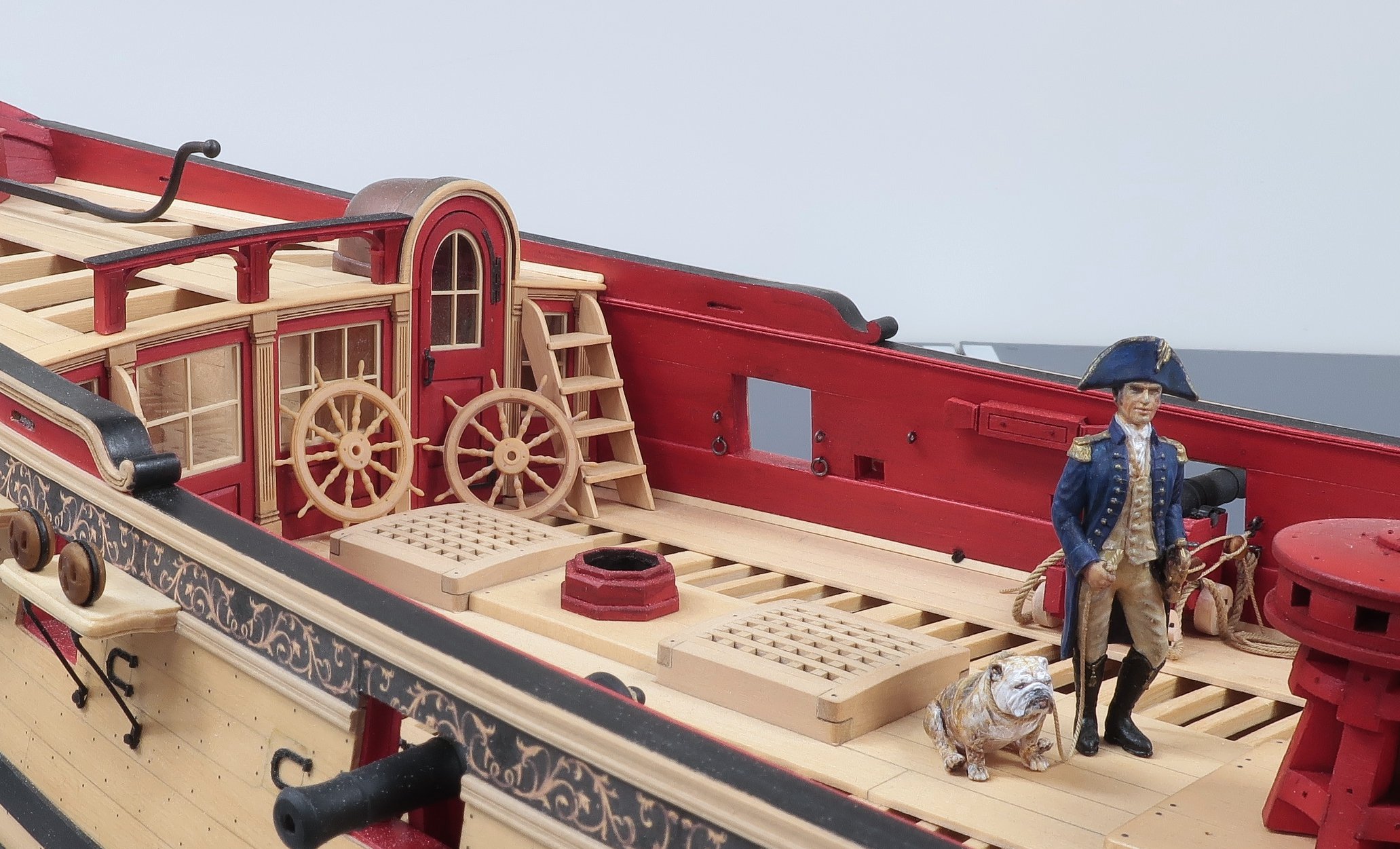
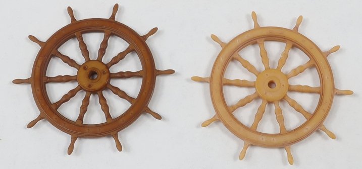
I was asked to show the color of the wheel on top of some boxwood. This is an even better way to see it in its actual environment. Dont look at the dust. When you see dust build up on your model like this that means you really need to do more actual model building, LOL. The wheel on the left is how you will get it and can use it straight out of the bag. It looks great. The one on the right has the wet on wet burnt umber wash. I will have the ten spoke 1/4" scale boxwood version in stock today. Its 1 1/4" in diameter. Its a very subtle difference dont you think. Too often I see folks over-do the application of a wash or weathering. You really just want to give it some tone. Chuck

-
Oh thats great. I havent tried the Minwax version. Any warm brown or will do according to your tastes. You really have to experiment.
-
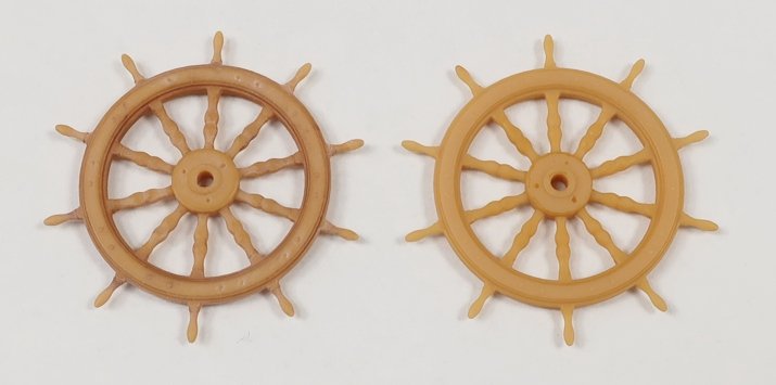
I forgot to add the photo showing what the unweathered 3D printed wheel that is Boxwood color will look like (on the right). This is how it will look when you get it and you can see how easy it is to just kick it up a notch. You guys should give it a try. Just a wet on wet wash of brown or burnt umber changes the appearance quite a bit. With my rigging blocks I do this for you in mass (not with acrylic paint). But because of the complex shape of a ship's wheel I cant really do that....it would just take too long. So its up to you.
-
New fittings to be available soon. Available in Boxwood color and a Swiss Pear. Ships wheel... I already have real Boxwood ship's wheel kits and will be keeping those in stock. I love those. These are just an alternative. Especially for those who really dont want to assemble 50 pieces and turn the spokes in a dremel. The Darker is good to go right out of the package. The Boxwood wheel is also great to use as is, but in this instance I wanted to show how it would actually look with a wet on wet wash to accentuate the grooves and details. It literally took 5 minutes. Too often I see folks just use this stuff straight away withought working on the appearance further. It does make a big difference. Wet down the wheel with your paint brush. Then working about a third of the wheel at a time while its wet, I applied some acrylic burn umber paint. The paint was also very very thin, wet, wet wet. Just brush it on while the wheel is still wet and then switch to a clean brush before it dries. Just touch the raised areas or the areas you want to remain lighter and it will soak up the very wet darker brown color. For example all around the outer rim face and the thicker areas of the spokes. The paint just erases away leaving the lighter color of the raw resin under it. You can also use weathering powders depending on what makes you feel more comfortable using. You can also use some wood stains....of your choice, I prefer Old Masters Fruitwood Gel stain. I show this because on certain items the 3d printed objects looks so great right out of the package....blocks for example. But others need some help so they dont look so perfect and clean making it hard to see the details. The darker "Pear" color doesnt need any work at all...for whatever reason that finish always looks great right out of the package. I went just a hair lighter on the darker pear finish for the wheels. I just thought it needed to be lighter and this is the way they will be sold. I am working on an eight spoke wheel now as well. So these will be available in the same sizes as my all boxwood kits. Basically a 1/4" and 3/16" scale wheel. And hopefully in both 8 spoke and ten spoke.
-
Nice progress. She is looking lovely.
-
question about waxing thread
Chuck replied to ford34tom@comcast.net's topic in Masting, rigging and sails
I dont use wax ever. My rope doesnt need it at all. It just obscures the detail of the rope and attracts dust which sticks to it like a magnet. Unless your rope is a fuzzy mess. Dont use it. Instead, run your rope through a alcohol flame rather than a candle flame because it wont leave soot. That gets rid of the fuzzies. But never wax. Best thing to do is buy better rope. No stretching, wetting or waxing needed. Just use it out of the package. Rope of Scale or Syren makes perfect rope. You just have to pick the one that you like better because the color tan and brown is slightly different from both sources. Chuck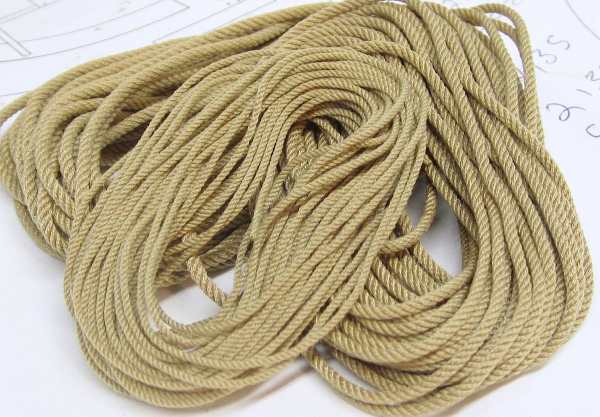
-
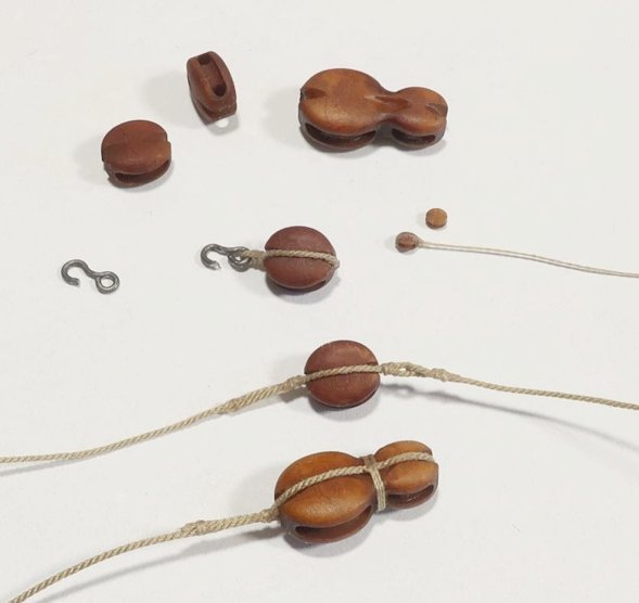
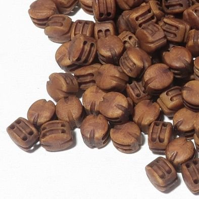
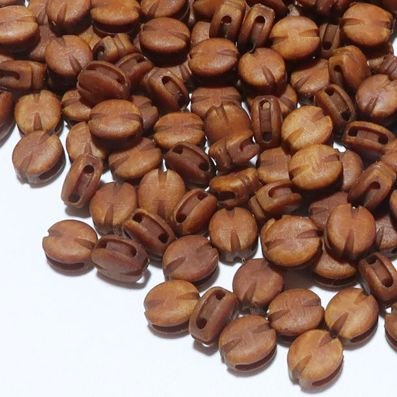
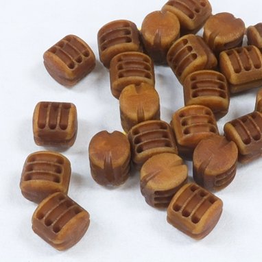
Thanks guys for saying. I am quite happy with the finish and color. And not just the darker Swiss Pear color blocks. The Boxwood 3D printed blocks are just as good and this is a much harder color and texture to pull off. I dont know of any other source for 3D printed blocks of this color . Here you can see the difference in the two colors. Chuck

-
After a weekend of busy sales...rest assured I should be restocked with blocks by tomorrow afternoon....You guys must be building a lot of ship models. Actually finishing up more 2mm single blocks as I write this. Then onto rope.
-
Lovely work Chris.
-
Oh my!!! That was sure some kind of machine, LOL. The plans are still out there if you can get parts. Google it!!!
-
You could easily use the Model Shipways ropewalk. Its flimsy and pricey for what you get but at $50 it will do the trick for just your own model. My more robust version of a ropewalk will hopefully be back soon and it is also easy to make your own. I used the MS ropewalk for years before I went into the rope making business. Chuck
-
As it seems many of you noticed, I opened the store yesterday around 3pm. Its all going quick...at this pace in another day or two it will be all gone again. I am very thankful as always. But I wont shut the store down again. Whenever I get around to restocking the items I will get around to it. Its just too much....so it will get done eventually. Sorry in advance for the wait times. Its gonna be a slog. Chuck
-
Actually my head stock and tail stock are 43 feet apart when I make my 30 foot lengths of rope. You were pretty close. LOL
-
Ok let me get this other group going for the capstan first and once I get caught up and running smooth with store again. Chuck
-
Yours would be just as good really. Its kind of hard to make bad rope actually once you get the feel for it. I think I mentioned this once before, we had a blackout a few years back and I was still able to make rope in complete darkness by feel. Once you learn it is absolutely like riding a bike. I think it took me slightly longer, LOL....maybe 8 minutes per package rather than 7, LOL.
-
Not at all. You dont have to make 30 foot lengths. You could easily make a 12 foot length on demand when you need it in about 10 minutes or less. Is it a luxury to have more space to make longer lengths....absolutely. But the beauty of some rope walks is the ability to make ropes of any length or thickness on demand. When I was making rope for just myself, I made 12 foot lengths. When I opened the store I started making 20 ft lengths and then increased that again to 30 ft for the same price to give folks more product for the same $$. So it was very economical for people to buy way more than they actually needed. But making it on your own, your costs will only be for the ropewalk and for the materials. The material cost is ridiculously low. Its the labor costs you guys are paying for. You can buy one spool of Guttermann Mara thread for $4.50 From that one spool of thread you can make 15 packages of .025 tan rope 30 feet long. Its all just the labor costs. So it is well worth giving it a try and even making shorter lengths. Chuck
-
Glenn, I dont think so. In this particular case, I think there was just an unfounded rumor floating around that I was retiring and shutting down the shop. That is far from the truth. I will repeat that I am going to be around for a whole bunch more years. Only two things will make me shut down earlier , I drop dead, or I hit the numbers. So there is no need for hoarding and I think folks will realize that when they see things stay the same once I reopen. But I will revamp my effort to teach and encourage folks to make rope on their own. I will make more video tutorials and even maybe a workshop or group project of some sort. I might possibly release my plans and files for my ropewalk and we could have a group build. You could make it without a laser cutter. I could work up a material list and the sources to buy the stuff needed. Would you guys be interested in that? Glenn I am curious...have you ever tried making your own? You would be good at it. You get to pick your own material and the color and even the infinite number of sizes you would be able to make. More than any store could sell. And make rope on demand the moment you need it. Chuck
-
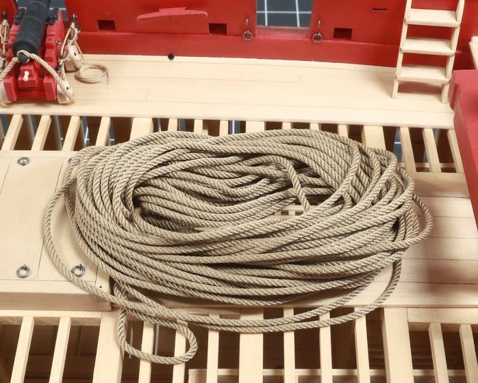
That is an option but for now I am good. I will just do my best and if folks have to wait a little bit for me to restock once in a while then hopefully it will be worth the wait. I used to have help with rope making but my son in law has moved on to other things. Ropewalks may be back in stock soon as well so hopefully more folks will try and make their own. They really should try it. Making rope for just one project you are working on, at the moment when you need it is just too easy...it takes less time than waiting for the mailman to deliver the stuff you buy from me or anyone else. This 30 foot length of rope literally took me 7 minutes to make and its perfect. Its only when you have to make 2500 feet of rope per day...every day... that it makes you want to stick a fork in your eye. Chuck

-
Thank God!!! I am on my last size of rope for restocking... Shouldnt be long now.
-
Lovely....so elegant!!!
-
People are sending me requests to join the group. Dont do this. This is just a quirk of the software. This is the way it will work. Once I finish setting up the tutorial topics. I will announce it is ready for folks to join. The NRG will add a store item to its online shop. You will have to go there and buy your access to the group for five bucks. We are still setting that up. Mary will contact me with your information and I will send you an invitation. You will see your the invation and will be able to click a link to accept it and join. Basically its the same way it works for the Winchelsea group build. Thats when you will gain access to download the files. If you are not 3d printing or laser cutting your parts, its free to join as you will be able to buy a kit and start a build log without paying $5. You only have to pay the five bucks for access to the files if you are making the parts yourself. Chuck
-
Yes that is so true. I never charged enough and I give too much away for free. And I work way too much. Life is too short. I hear that from her every day lately. LOL... I guess this is a good post to give an update on the capstan project. Another brilliant business decision. I have completed the build log and added all of the files for download. I just have to write a few topics of instruction for the materials I am using and the techniques I used...all of my secrets and methods. Then folks will be able to join this project area and download those files and make their own kit. If you dont have a laser cutter or 3D printer, thats OK too. J.J. (scrubbyjoe) has agreed to produce these kits for sale so folks can buy one and join the group to start a build log alongside the others. That is free and you could a tually start a topic in that area right now if tou wanted to. I dont suspect we will have a lot of people who will be laser cutting their own stuff or 3D printing their own stuff yet. But I do think that this number will increase in the future. And yes I am giving this project away for free and J.J. has my permission to produce these and sell them. If anyone else wants to, they must get my permission first or you can just use the material for your own personal use. This is all new territory and we are testing out a new way to bring projects to our members. Having said this, We will be charging a small fee to join this club area for the downloads only. Not so MSW can make a killing off it, but so we can keep track of those with access and manage the release of the files out to the world. The cost to gain access and be invited to download these files is just $5. Just five bucks, LOL. So yes, please dont tell my wife that I am giving away something else, LOL I will never make the Forbes 500, LOL But everyone have fun. Chuck
-
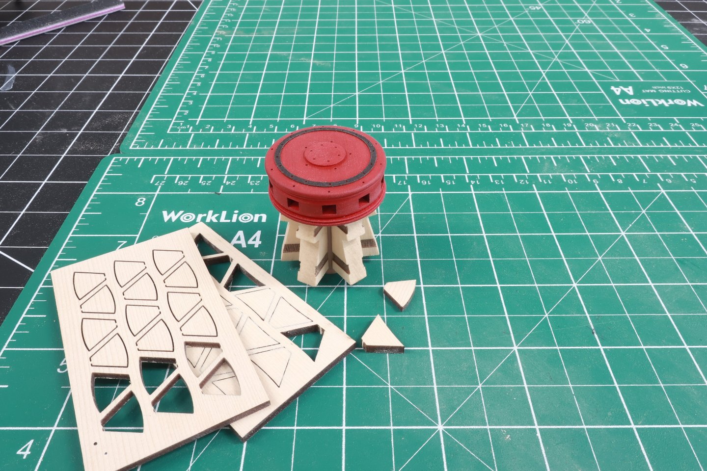
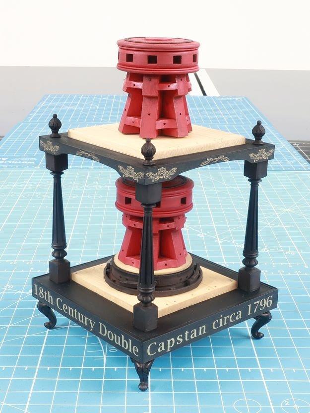
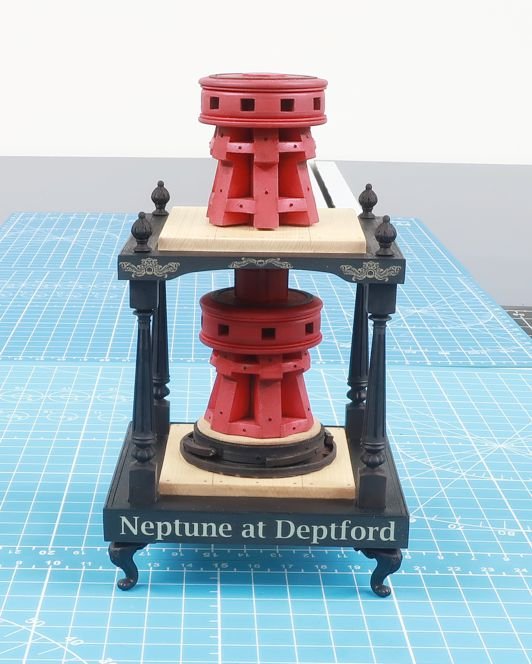
You should add the chocks just like you did for the lower capstan. They are the same sizes and from the same laser cut sheet. From this point its all the same. Paint the capstan red and add the bolts on the whelps and chocks. Not to rush this in the instructions but it is literally the same as you did for the lower capstan. That finishes it all up. With a tiny stick glued into the center square hole on the bottom, sit the upper capstan in position. The square stick should easily slide into the square hole on the lower capstan. Hopefully the two center shaft parts actually meet and touch each other so you can glue it into position permanently. But if you need to use an optional spacer...this is the time to try it. You dont want the upper capstan marking up the upper capstan partners when it rotates. If the upper capstan is too high however and there is too much space between the bottom of the whelps and the partners, sand down the center shaft until it fits better. I hope that makes sense. This leaves only one more step before you complete the model. You can add the four 3D printed finials to the corners. Just sand the bottom of these flat so they sit nicely on the surface. Make sure you glue them directly over the columns so they look like they are supposed to look. They should look like an extension of the those four columns. Thant completes your model. Note how the chocks are positioned differently on the upper and lower capstan. This is pretty typical and an interesting detail. Also note how for these later capstan designs there are no pawls onthe upper deck at all. Again very typical and why I chose this later design as the subject of this project.

- 23 replies
-
- 10
-

-
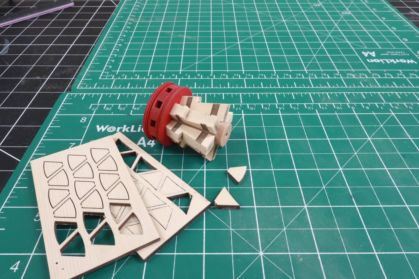
OK, the center stick you have pushed into the hole on the bottom of the capstan drum can be glued in there permanently. It doesnt have to be very long at all. Maybe even just 3/16 - 1/4" long. It just has to be long enough that you can glue the last 3d printed center column section onto it. The circular end is the bottom. Glue that onto the stick. Make sure the ends are sanded flat before you do so to prevent any gaps all around when the two pieces are pushed together. You can see below that after the whelps for the upper capstan are sanded free of char and glued onto the center shaft, the round portion of that shaft is visible. This will be slid into the hole in the center of the upper capstan partner. Test it in position. Note where the bottom of the whelps fall in relation to that circular part of the shaft. Once you have the whelps all sanded and glued onto the shaft, test its fit on the partners. There should be just a little bit of space between the bottom of the whelps and capstan partners. It should sit right on the capstan partners. It shouldnt be touching it. It should be just a hair off the surface. Now when it comes time to place the finished upper capstan on the model, you will push another 1/8" stick into the hole on the bottom of the capstan. Then this is pushed into the cenetr hole of the lower capstan making a nice solid connection. But maybe for whatever reason, you will need to raise your upper capstan a bit more so it doesnt rub against the upper capstan partner. There are laser cut optional spacers you can add between the upper and lower capstan so you can adjust its height if you need to. But I get ahead of myself here. We still have to add all the chocks between the whelps for the upper capstan. Yes I also painted the upper capstan drum to get ahead of the painting and also added the laser cut iron ring which is made from black laserboard.